As an Amazon Associate, we earn from qualifying purchases. Some links on this site are affiliate links at no extra cost to you. Our recommendations are based on thorough research and editorial judgment.
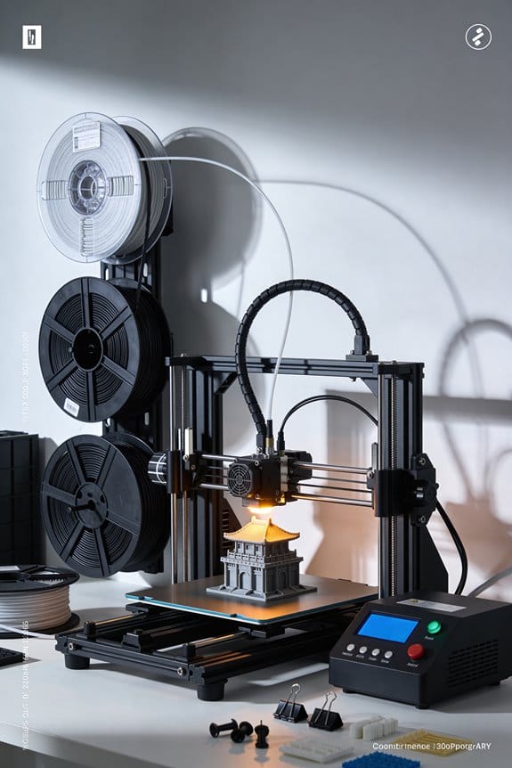
The Anatomy of a NEMA 17 Stepper Motor Inside Modern 3D Printers
You just swapped motors on your 3D printer and now the X axis jitters or the Z moves feel sluggish — which exact motor spec fixed that problem? Or you’re choosing a replacement and can’t tell whether to prioritize current, torque, or step angle. Most people focus on size or brand and ignore electrical specs and wiring choices that actually determine performance. This article will show you, step by step, how to match a NEMA 17’s rated current, resistance and inductance to your driver and mechanics so the axis moves smoothly; you’ll learn which step angle and microstepping tradeoffs suit X/Y versus Z and when to wire coils series or parallel.
I’ll also give practical cooling, mounting and cabling tips to avoid overheating and missed steps. It’s simpler than it looks.
Key Takeaways
If you’ve ever held a 3D printer motor, this is why those numbers matter.
– NEMA 17 means the motor has a 42×42 mm faceplate you can bolt to your printer mount; measure the plate to confirm fit before buying. Example: on a Creality Ender 3, the NEMA 17 mounts line up with those four 3 mm screws.
Before explaining how to pick one, here’s why the step angle matters in one sentence: your layer and movement resolution depend on the step angle.
- Step angle and resolution
- Typical motors are 1.8° per step, which gives 200 steps per revolution; that’s the default in most firmware. Example: with a 20-tooth GT2 pulley on an extruder, each full step moves the belt about 0.04 mm.
- Some motors are 0.9° (400 steps/rev) and give double native resolution; you’ll get smoother small moves but need drivers and firmware set up for it.
- If you want finer motion without changing microstepping, choose 0.9° motors.
- Holding torque (N·cm) tells you how much force the motor resists when powered; pick one with at least 30–40 N·cm for most hobby printers. Example: a 40 N·cm motor will handle modest multi-material prints without losing steps.
- Rated current (A) is the maximum current the motor expects; set your driver to 70–85% of that value for safe continuous use (e.g., if a motor is 1.7 A, set driver to ~1.2–1.45 A). Short sentence.
- Phase resistance (Ω) and inductance (mH) shape how the motor behaves at speed: lower resistance usually means higher current and more heat, higher inductance smooths motion but reduces top speed.
- Microstepping smooths motion and reduces resonance; set 1/16 or 1/32 for printers—1/16 is a good balance of smoothness and performance on many boards. Example: using 1/16 microsteps on a 200-step motor gives 3,200 steps per revolution.
- Set current limit to 70–85% of the motor’s rated current using the driver’s potentiometer or firmware value to prevent overheating. Short sentence.
- Higher microstepping reduces audible noise but doesn’t increase full-step torque; expect about the same holding torque regardless of microsteps.
- Wiring: for bipolar motors with two coils, you can wire the coils in series or parallel—series increases torque at low RPM, parallel helps at higher RPM. Example: a 1.5 A motor wired in parallel will draw more current per coil and keep torque better at 2000+ RPM.
- Shaft type: choose a smooth shaft for couplers or a D-flat shaft for easy gear mounting; measure shaft diameter (usually 5 mm) before ordering couplers.
- Torque vs RPM: expect torque to drop as RPM increases; if you push for very fast travel, get a motor with higher rated torque or adjust gearing. Short sentence.
Holding torque, current, resistance: why this trio matters in one sentence: they determine whether the motor can push your axes without skipping or overheating.
2. Key electrical specs
Before you fiddle with the driver, know why driver settings matter in one sentence: they control smoothness, torque delivery, and how hot the motor runs.
3. Driver settings and microstepping
Wiring and mechanical choices matter because they change torque behavior and shaft compatibility in one sentence.
4. Wiring, shaft, and speed tradeoffs
If you want a quick checklist, here’s what to do.
5. Quick shopping and setup steps (numbered)
- Measure your mount: confirm 42×42 mm and screw spacing.
- Pick step angle: 1.8° for standard, 0.9° for higher native resolution.
- Choose torque: aim for 30–40 N·cm or higher for robust prints.
- Set driver current: 70–85% of rated current (use a multimeter or firmware).
- Decide wiring: series for low-speed torque, parallel for higher-speed torque.
- Match shaft and coupler: usually 5 mm, confirm D-flat if you need it.
Final practical detail: keep an eye on motor temperature — it can be hot but should stay below ~80°C during long prints.
Quick Selection Guide: Which NEMA 17 for X, Y, or Z
Before you choose a NEMA 17, you need to know what each axis actually does and why that matters.
For X and Y: prioritize torque and responsiveness. Why that matters: those axes move quickly and need steady holding to prevent layer shifts. Example: on a 200 mm/s print with 0.1 mm layers, a weak motor lets acceleration cause ghosting across the print flank. Steps to pick one:
- Match motor holding torque to your moving mass — aim for 40–60 N·cm (56–84 oz·in) for typical Cartesian printers with a 200–400 g hotend/carriage.
- Check the motor’s current rating and match your driver; set driver current to 70–85% of the motor’s rated current to avoid overheating.
- Prefer motors with a 1.8° step angle and consider microstepping-capable drivers for smoother motion.
A concrete example: use a 1.8° 59 N·cm motor rated 1.5 A for a CoreXY with a 300 g carriage and 200 mm/s max speed.
For Z: favor higher torque at low speed. Why that matters: Z lifts and holds the bed or hotend precisely, so stall torque at low RPM matters more than top speed. Example: lifting a 1 kg heated bed with lead screws needs steady torque to avoid layer compression on long prints. Steps to pick one:
- Choose 60–80 N·cm if you have a heavy bed or use coarse lead screws; 40–60 N·cm can work for lighter beds or fine screws.
- Use motors with lower rated current if your drivers or controller board limit current; run them slower for better torque.
- Consider using two motors in parallel for larger beds — wire them to separate drivers or a twin-motor driver.
A concrete pick: two 59 N·cm motors at 1.2 A each on a large heated bed with 8 mm lead screws.
Microstepping and drivers: microstepping improves resolution and reduces vibration, and that matters because smoother motion yields cleaner prints. Example: switching from 16 to 32 microsteps reduced visible stepping on a 0.4 mm nozzle test cube. Steps:
- Verify your driver supports the microstepping you want (e.g., 16×, 32×).
- Increase microstepping if you need quieter, finer motion; expect slightly less torque per microstep.
- Adjust motor current and acceleration in firmware after changing microstepping.
Current, temperature, and matching to your frame: matching rated current to your driver and load matters so you don’t overheat or underpower the motor. Example: a 1.7 A motor set to 2.0 A on a Prusa-style board will run hot and shorten life. Steps:
- Check motor rated current and set driver RMS to 70–85% of that value.
- Monitor motor temperature after an hour of printing — acceptable surface temps are generally under 70°C.
- If temps exceed 70°C, lower current or add cooling.
Cabling and terminations: plan cable routing early because leads flex and connectors fail from fatigue. Example: a ribbon cable across the X gantry failed at 40,000 cycles; switching to a coiled cable loop solved it. Steps:
- Route wires so they bend gradually; avoid tight loops under 15 mm radius.
- Use strain relief and secure connectors to the frame.
- Choose termination style (soldered pigtail, Molex, JST) that matches your harness and allows easy replacement.
Quick checklist you can use now:
- X/Y torque: 40–60 N·cm typical; heavier setups up to 80 N·cm.
- Z torque: 60–80 N·cm for heavy beds; two motors if bed > 1.5 kg.
- Step angle: 1.8° standard.
- Driver current: set to 70–85% of motor rated current.
- Microstepping: 16× or 32× for smoother, quieter prints.
- Cable bend radius: >15 mm, use strain relief.
Pick specific motors by matching those numbers to product specs, then order matching drivers and connectors.
Physical Form: Size, Shaft & Mounting Specs
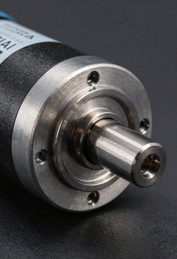
Before you mount a NEMA 17 stepper motor, know why the faceplate size matters: it tells you exactly where the mounting holes will line up so your bracket fits without modification. The motor has a compact square faceplate that measures 42 mm by 42 mm, so if your printer or CNC carriage uses that pattern your bolt holes will match. Example: a 3D printer X-carriage with the standard 42×42 pattern will accept a NEMA 17 with M3 screws spaced at the corners without redrilling.
Think of the shaft like the link between the motor and whatever moves your machine. You’ll most commonly see a 5 mm D-cut shaft that gives a flat for set screws, which prevents pulleys or gears from slipping under torque. Example: when fitting a GT2 pulley for a belt-driven printer, slide the pulley onto the 5 mm D-cut shaft, align the flat, then tighten the M3 set screw to 1–2 N·m torque.
The frame depth tells you how much of the motor sticks out from the mounting surface and why that matters for clearance. Typical NEMA 17 frame depths are around 37.5 mm, so if your gantry has a 40 mm slot the motor will fit behind the carriage without interfering. Example: mounting on a compact printer gantry with 45 mm vertical clearance leaves you roughly 7.5 mm of extra space for wiring.
Before you connect a motor to hardware, check the mounting holes and bolt size so your screws sit flush and don’t obstruct movement. Mounting holes follow the NEMA spacing with M3 or M4 bolts depending on the specific model; use countersunk screws or recessed heads so they don’t rub on moving parts. Example: using M3 countersunk screws on a NEMA 17 keeps the screw heads flush with a 42×42 mounting plate.
You should confirm weight and model variations because they affect inertia and the torque you’ll need. Weights vary by a few tens of grams between models; a heavier motor can handle more inertial loads but may slow acceleration. Example: swapping to a heavier 200 g NEMA 17 on a lightweight carriage may require you to reduce acceleration from 3000 mm/s² to 2000 mm/s².
Steps to pick and mount a NEMA 17:
- Measure your mounting pattern — confirm 42 mm × 42 mm spacing.
- Choose shaft type — pick 5 mm D-cut for pulleys or round if you use clamp couplers.
- Select screws — M3 or M4 countersunk bolts to sit flush with the faceplate.
- Check depth and clearance — ensure ~37.5 mm depth fits your enclosure.
- Tighten set screws to specified torque (typically 1–2 N·m) and route wiring away from moving parts.
If you follow those steps, your motor will fit and couple reliably.
Electrical Specs: Current, Voltage, Resistance & Inductance
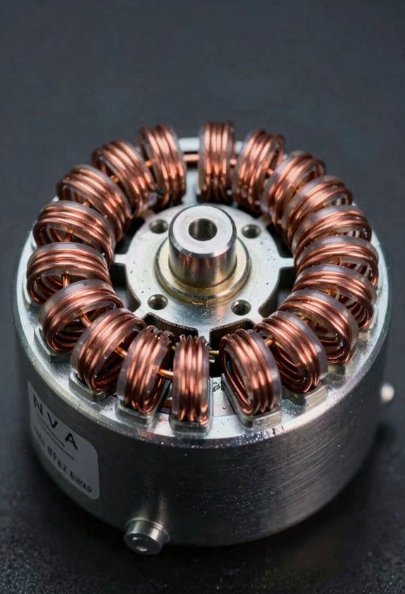
Think of motor electrical ratings like the rules of the road for current and voltage — they tell you how to drive the motor safely and predictably. Why it matters: if you ignore these numbers you can overheat the motor, lose steps, or harm the driver.
Rated current per phase (typically 1.2–1.8 A)
- Why it matters: this number sets the motor’s thermal and torque limits.
- How to use it:
- Set your driver current limit to the motor’s rated value or slightly below (for example, 1.5 A for a 1.5 A motor).
- If your driver lets you reduce current in software, start at 80% and test torque under the expected load.
– Real-world example: a 1.5 A NEMA 17 on a small CNC router stalled when the current was set to 0.9 A; setting it to 1.5 A restored reliable motion.
Rated voltage, phase resistance, and inductance
- Why it matters: these determine how quickly current rises in the winding and how the motor responds at higher step rates.
- How to use it:
- Compare the motor’s phase resistance (for example, ~1.86 Ω) to your supply voltage to estimate idle current heating.
- Use the motor’s inductance (3–8 mH typical) with resistance to get the electrical time constant τ = L/R; smaller τ means faster current changes and better response at high step rates.
– Real-world example: a stepper with 1.86 Ω resistance and 5 mH inductance has τ ≈ 2.7 ms, which explained why it lost torque above 8 kHz step rates on a particular driver.
Practical protection and performance steps
- Why it matters: proper power management prevents damage and keeps motion predictable.
- How to use it:
- Choose a current-limited driver and set the limit to the motor’s rated current.
- Provide cooling (small fan or heatsink) if the motor runs near its rated current for long periods.
- If you need higher speed, raise supply voltage but keep current limited — higher voltage helps overcome inductance limitations.
– Real-world example: switching from 12 V to 36 V supply with current limiting allowed a printer’s motors to keep torque at higher print speeds without overheating.
Quick checklist you can follow
– Why it matters: a checklist keeps you from missing critical specs.
- Note motor rated current and set driver limit to that value.
- Record phase resistance and inductance; compute τ = L/R if you expect high step rates.
- Add cooling if continuous duty near rated current.
- Use higher supply voltage only with current limiting enabled.
If you follow those steps, your motor will run cooler and behave more predictably under load.
NEMA 17 Torque, Step Angle & Speed for Printing
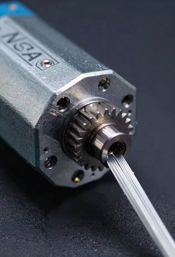
Think of torque like the motor’s muscle for moving and holding stuff in place.
Why it matters: If your printer has a heavy extruder or you want fast acceleration, you need enough torque or you’ll get skipped steps. Example: a Bowden setup with a direct-drive upgrade — adding a 60 g metal extruder can make a 44 N·cm motor struggle at 3000 mm/s² acceleration on the X axis. For practical steps:
- Aim for 44–55 N·cm holding torque for most single-extruder desktop printers.
- If you add a heavy extruder or run high accelerations (≥3000 mm/s²), choose 55–70 N·cm.
- If you want quieter motion and can accept slower acceleration, a 40 N·cm motor is often fine.
Step angle sets the motor’s base position increment and thus how finely you can place the nozzle.
Why it matters: Your layer lines and micro-movements depend on this base step size. Example: printing a 20 mm calibration cube with a 0.4 mm nozzle on a 200-step (1.8°) motor gives coarser native steps than a 400-step (0.9°) motor, which yields smoother slow moves. Practical guidance:
- Use 1.8° (200 steps/rev) for typical printers; it’s cheaper and reliable.
- Choose 0.9° (400 steps/rev) if you need extra native resolution for very slow detailed prints.
- Combine microstepping (e.g., 16x or 32x) with either motor to smooth motion and reduce audible stepping; set your firmware step-per-mm accordingly.
Speed limits depend on how torque falls off with RPM and how your driver and mechanics behave.
Why it matters: High speeds cut torque and can excite resonances that ruin prints. Example: your X axis might feel fine at 40 mm/s but start ringing and losing steps around 150 mm/s because torque dropped and a resonance was hit. Do this:
- Check the motor torque curve from the datasheet and expect usable torque to drop above ~1000–1500 RPM for many NEMA 17 motors.
- Tune your current limit on the driver to about 70–85% of the motor’s rated current to balance torque and heat.
- Use slow acceleration ramps (e.g., increasing from 500 to 3000 mm/s² in 500 mm/s² increments during tuning) and test for missed steps at each increment.
- If you get wobble at certain speeds, try changing microstepping, adding mechanical damping (rubber feet, heavier bed), or enabling input shaping on your firmware.
A final practical checklist you can run through:
- Pick torque based on payload: 44–55 N·cm for standard setups, 55–70 N·cm for heavy extruders.
- Choose step angle: 200 steps/rev for general use, 400 for higher native resolution.
- Set driver current to 70–85% of rated, then tune accelerations in small increments while watching for skipped steps.
- If resonance appears, adjust microstepping, add damping, or enable input shaping.
If you follow those steps, your NEMA 17s will be matched to your printer’s weight, speed, and print quality goals.
Wiring, Colors & Connector Options (Series vs Parallel)
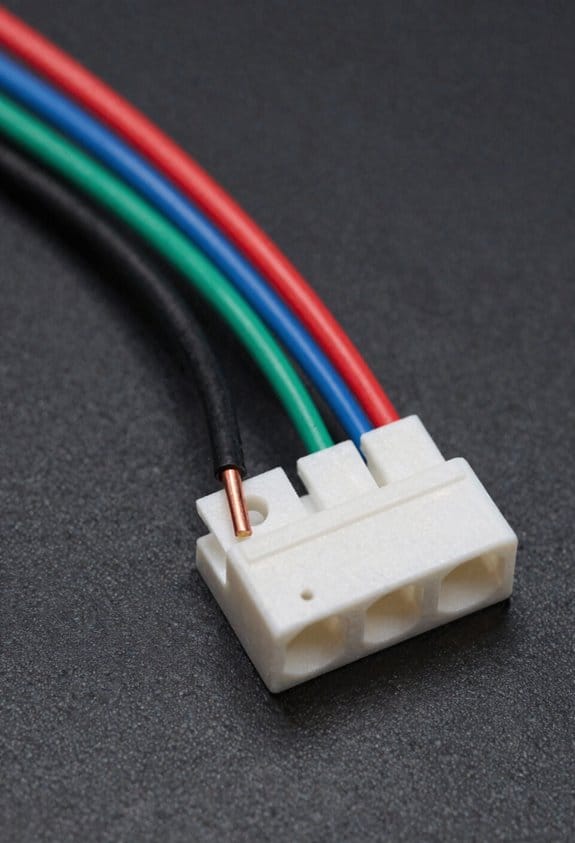
Before you wire your stepper motor, know that wiring choices change current draw, heat, and how well the motor pairs with your driver.
After you size motors for torque, step angle and speed, you’ll need to connect the coils correctly and pick the right connector style because wiring affects performance and reliability. Standard NEMA 17s use four leads; the common color mapping is A+ black, A- green, B+ red, B- blue, which matches most driver pinouts and prevents you from swapping phases. Example: if your Z-axis motor on a Creality board skips after a board swap, checking that black→A+, green→A-, red→B+, blue→B- fixed it immediately.
Why series vs parallel matters: wiring phases in series doubles the phase inductance and halves phase current for a given driver voltage, which increases low-speed torque but limits top speed. Wiring in parallel halves inductance and doubles the current per phase (so your driver must supply more), which improves high-speed torque and responsiveness. Example: on a direct-drive extruder that stalls at low RPM, switching a 1.8° NEMA 17 from parallel to series raised holding torque at low speed and stopped layer shifts during retraction.
How to decide and connect (steps):
- Check your driver current limit and voltage. If your driver maxes at 1.2 A per phase, parallel wiring that requires 2 A will overload it.
- Measure or look up motor coil resistance and inductance. If each coil is 2 Ω and 4 mH, series becomes 4 Ω and 8 mH, parallel becomes 1 Ω and 2 mH.
- Choose series for prints with heavy layers and low speeds; choose parallel for fast moves and small layer heights.
- Rewire: identify the two coils (A and B), then either join one end of coil A to one end of coil B for series (solder/heat-shrink that join), or join the two A ends together and the two B ends together for parallel. Use a multimeter continuity check after soldering.
- Set the driver current limit after wiring; measure motor idle current and tune down to the lowest value that avoids missed steps.
Connector and termination choices: decide on bare leads, crimp pins, or Molex based on serviceability and space because connectors affect strain relief and EMI. Example: on a printer with frequent hotend swaps, using Molex KK 4-pin housings with crimp pins made it easy to swap motors without soldering and prevented broken wires at the coil entrance.
- Use bare leads if you have fixed wiring and plenty of strain relief.
- Use crimp pins + housings for modular builds where you may unplug motors.
- Use keyed Molex or JST for compact runs; verify pin size matches wire gauge (22–26 AWG common).
Cable management and noise control: do these things to reduce failures and interference because loose cables cause wear and signal noise. Example: bundling the motor cable with a spiral wrap along the X-carriage prevented the cable from rubbing through insulation after 200 hours.
- Route cables with gentle bends (radius ≥ 10 mm).
- Anchor near the motor with a clamp; leave 10–20 mm of service loop.
- Twist the two phase pairs together or use shielded cable if you see stepper chatter on long runs.
- Avoid running stepper cables parallel to thermistor or heater wires for more than 50 mm.
One last check: always verify phase mapping with a continuity test and set the driver current after you rewire, because mistakes here cause heat and skipped steps.
Thermal Limits & Environmental Operating Range
Before you run a motor in a new environment, you need to know how temperature and humidity change its performance.
Because stepper motors convert electrical energy into motion, temperature affects how much torque you get and how long the motor lasts — higher temps raise winding resistance and reduce torque. For example, a NEMA 17 rated for -20°C to +50°C will lose measurable torque near 50°C; measure winding temp with an infrared gun and keep it below 80°C. Use a small fan or add ventilation holes if the enclosure surface approaches that temperature.
Why humidity matters: moisture speeds corrosion and can degrade insulation, which shortens motor life. Check for visible rust on the shaft and connector pins after six months in a damp shop; that’s a clear sign humidity is harming the motor. Keep relative humidity below 60% using a dehumidifier or silica gel packs inside sealed enclosures.
Thermal cycling causes expansion and contraction that leads to material fatigue in solder joints and bearings, and that shortens mean time between failures. A concrete example: a 3D printer in a garage that heats to 40°C during printing then cools to 10°C overnight will develop loose connector solder over 1–2 years. To reduce cycles, avoid letting the enclosure temperature swing more than 10°C between on and off.
Practical steps you can take:
- Monitor temps: use an infrared thermometer or a thermocouple on the motor housing and log readings daily for a week to see patterns.
- Control humidity: target <60% RH; place a 500 g silica gel cartridge in any small enclosure or run a compact dehumidifier in a larger room.
- Stabilize heat sources: if heaters cause rapid cooling afterward, add a soft-start or limit heater duty cycle so temperature changes under 10°C per hour.
- Improve cooling: add a 40–80 mm fan blowing across the motor if winding temps exceed 70°C during peak loads.
- Inspect regularly: every 3 months check for corrosion, insulation cracks, and play in bearings; replace the motor if you see visible bearing wear.
A quick real-world check: tape a small thermocouple to the motor housing, run the highest-load job for 30 minutes, and read the temperature — that tells you whether you need added cooling or better ventilation.
Choosing NEMA 17 for RepRap, LulzBot & Common Printers
Before you choose a stepper for a RepRap or LulzBot-style printer, you should know why the motor standard matters in practice.
I recommend NEMA 17 because its 42×42 mm mounting pattern, compact frame, and common electrical specs fit most hobby and prosumer printer frames. Example: swapping a NEMA 17 on a Prusa i3 clone usually only takes the time to remove four screws and reconnect a single four-pin plug. Check these specific things before you buy.
Why matching current and inductance to your driver matters: if the motor draws more current than your driver can supply you’ll overheat the driver, and if inductance is wildly different you’ll lose high-speed torque. Example: a 1.7 A per-phase NEMA 17 (rated 1.7 A, 1.5 mH) works well with an A4988 or DRV8825 set to 0.7–1.0 A limit; a 2.8 A motor needs a stronger driver or different current limit.
1) Check rated current and inductance.
2) Compare those numbers to your driver spec sheet.
3) Set your driver current limit accordingly.
You should confirm shaft type and coupling fit because shafts differ and a wrong shaft wastes hours. Example: many extruder couplers expect a 5 mm smooth shaft; if your new motor has a 6.35 mm D-shaft you’ll need a different coupler or a new motor.
1) Verify shaft diameter (e.g., 5 mm vs 6.35 mm).
2) Match coupler bore or buy a shim/adapter.
3) Tighten grub screws to recommended torque.
Holding torque determines axis stability and print quality; higher torque reduces missed steps on Z lifts and long retractions. Example: a 42 N·cm NEMA 17 will hold a heavy pancake extruder better than a 20 N·cm motor during fast retractions on TPU.
1) Compare torque ratings in N·cm or oz·in.
2) Choose ~30–50% more torque for heavy direct-drive setups.
3) Test with a print that includes tall, thin towers.
Bed leveling systems and probes rely on consistent Z movement, so motor torque changes your auto‑level behavior. Example: a weak Z motor on a 300×300 mm bed can cause sagging during mesh probing and give false probe readings.
1) Use a motor with enough torque for your bed mass.
2) If using auto‑level, confirm probe repeatability after swapping motors.
Filament retraction needs relate to torque and microstepping because torque drop at high microsteps can soften retractions and cause stringing. Example: switching from a 1.7 A motor to a higher inductance 2.0 A motor might require you to increase retraction length by 0.5–1 mm.
1) Note your current retraction settings.
2) After fitting a new motor, print a retraction test (20 mm towers).
3) Adjust retraction length and speed as needed.
Finally, match wiring and connector style so you don’t need to solder or add adapters. Example: if your board uses JST-XH 4-pin and the motor has open leads, buy a JST plug or a prewired motor with the right connector.
1) Check connector type (JST, Molex, bare leads).
2) Buy the right cable or adapter.
3) Label wires when you disconnect them.
If you follow these checks—current/inductance, shaft type, torque, probe behavior, retraction test, and connector match—you’ll avoid most replacement headaches and get a motor that works with your printer right away.
Upgrading Accuracy: 0.9° Motors, Encoders & Closed‑Loop Options
If you’ve ever missed a print detail because your motor skipped, this is why.
Why it matters: missed or imprecise steps make small features look rounded or shifted. For example, if you’re printing a 0.5 mm gear tooth and the motor loses a step, the tooth can come out visibly deformed.
0.9° motors: what changes and why you might pick one
Why it matters: using a 0.9° motor doubles your native steps, so you get finer positional resolution without extra electronics.
Example: switching a NEMA 17 from 1.8° to 0.9° gives you 400 full steps per revolution instead of 200, so a 20-tooth pulley moves in 0.045° per full step instead of 0.09°, which can make thin walls print cleaner.
Steps to use a 0.9° motor:
- Replace the motor with the same mounting and wiring spec.
- Set your firmware motor steps-per-mm to double the previous value (for a typical 1.8° motor at 200 steps/rev, change to 400 steps/rev).
- Keep your current current/drive settings but verify temperature and torque under load.
- Test a calibration cube and adjust acceleration if you see ringing.
Notes and trade-offs: a 0.9° motor gives finer resolution but slightly less torque per step and can be more sensitive to driver current settings; your drivers still need correct current limits.
Encoders and closed-loop control: how they help
Why it matters: encoders let the controller detect and correct missed steps so your motor follows the intended position under load.
Example: adding a 1,024 CPR (counts per revolution) encoder to an axis helped a user stop losing steps when printing long, tall calibration towers at high speeds.
How to add closed-loop feedback:
- Pick an encoder rated for your shaft speed and environment (e.g., 1,024 CPR incremental magnetic encoder).
- Wire the encoder to your controller or a closed-loop driver that supports feedback (check compatibility like Trinamic TMC-series closed-loop options).
- Enable closed-loop mode in firmware or driver settings and tune the gain/compensation parameters per the manufacturer’s guide.
- Run a move test and inspect with aouc or logging to confirm encoder and motor stay synchronized.
Trade-offs: encoders add cost, require wiring and firmware or driver support, and need tuning; they salvage accuracy under load and reduce layer shift risk.
Combining microstepping with closed-loop: the smoothest motion
Why it matters: microstepping smooths motion and reduces vibration, while closed-loop corrects position errors, so together you get both smooth and accurate movement.
Example: using 16x microstepping plus a 1,024 CPR encoder reduced visible banding on a user’s 0.2 mm layer prints on an overhung bridge.
Practical setup steps:
- Choose microstepping (e.g., 16x) on your stepper drivers.
- Add the encoder and enable closed-loop as above.
- Tune microstepping current and closed-loop gains; lower current can be used because feedback prevents lost steps.
- Print a fine test object (e.g., 0.5 mm gear) and iterate settings until you see clean edges.
Bottom line: pick a 0.9° motor if you want higher native resolution with minimal electronics changes; pick encoders/closed-loop if you need to prevent missed steps and improve accuracy under load; use both plus tuned microstepping for the best smoothness and positional fidelity.
Troubleshooting: Noise, Missed Steps & Overheating
If you’ve ever had a noisy or skipping NEMA 17, this is why. You care because noise and missed steps ruin prints and can damage hardware.
Why this matters: fixing the real cause saves you time and prevents repeat failures.
1) How do I tell noise and missed steps apart?
- Check bearings first because worn bearings make noise and add friction that causes missed steps. Example: if your printer makes a grinding sound at the start of a long X-axis move and the carriage stalls after 10 mm, a rough bearing is likely.
- Steps:
- Power off and manually move the axis; feel for rough spots or play.
- Spin the motor shaft by hand; listen for scraping or clicking.
- Wiggle the shaft laterally—> if you feel more than ~0.2 mm play, replace the bearing or motor.
– Takeaway: noisy grinding + added resistance = bearing issue.
2) What driver settings should you change and why?
Why this matters: wrong driver settings cause torque loss, skipped steps, and heat.
- Example: on an A4988 or TMC2209 controlling a 1.8° NEMA 17 with 1.5 A rated current, wrong current limits make the motor stall on acceleration.
- Steps:
- Set microstepping to 16x or 32x for smoother motion; change jumpers or firmware accordingly.
- Adjust driver current limit to ~70–90% of the motor’s rated current (for a 1.5 A motor set ~1.05–1.35 A). Use a multimeter or measure Vref per driver docs.
- Reduce stepper driver decay or torque settings if your driver supports it (e.g., TMC family): try lower torque/gradient settings to cut heat while maintaining steps.
– Takeaway: match microstepping and current to the motor spec to reduce skips.
3) How do I reduce vibration and resonance?
Why this matters: vibration causes noise and can look like missed steps due to lost microsteps.
- Example: at 60 mm/s a printer with a direct-drive NEMA 17 might resonate, causing visible banding and a buzzing frequency around 200 Hz.
- Steps:
- Add a simple rubber damper between the motor and mount (vibration isolator). Use one rated for your motor’s mounting hole pattern.
- Tune acceleration and jerk in firmware: lower acceleration by 20–50% and test prints at 30, 40, then 50 mm/s to find the sweet spot.
- Try tuned acceleration profiles: use S-curve or jerk-limited motion if your firmware supports it.
– Takeaway: mechanical damping + conservative accelerations reduce resonance.
4) What about overheating?
Why this matters: overheating can reduce magnetic strength and change resistance, causing missed steps and shortened motor life.
- Example: if your motor housing is >70°C after a 10-minute print while ambient is 25°C, it’s overheating.
- Steps:
- Measure motor temperature after a 10-minute run with your hand (too hot to hold) or an IR thermometer; aim <60°C.
- Lower driver current in 10% increments until temperature drops below 60°C while watching for skips.
- Improve cooling around the driver (small fan) rather than cranking current.
– Takeaway: keep motor under ~60°C and favor driver cooling over excess motor current.
Final quick checklist you can run in 15 minutes:
- Manually feel for bearing roughness and shaft play.
- Spin motor by hand and listen.
- Set microstepping to 16x–32x.
- Set driver current to 70–90% of motor rating and check Vref.
- Add a rubber damper and reduce acceleration by 20–50%.
- Verify motor temp <60°C after a 10-minute run.
If a step still gets missed after all this, swap the motor with a known-good NEMA 17 for one test; that isolates motor versus electronics and mechanics.
Frequently Asked Questions
Can a NEMA 17 Run Directly From a 3.3v Microcontroller GPIO Pin?
Like a square peg in a round hole, no — I can’t drive a NEMA 17 from a 3.3V GPIO drive directly; voltage mismatch and current limiting matter, so you need proper driver requirements and a dedicated stepper driver.
Are There Specific Lubricants Recommended for the Motor Shaft Bearings?
Yes — I’d use light machine oil for occasional light lubrication and a low-viscosity synthetic grease for longer-lasting protection; I’d avoid heavy greases, apply sparingly to bearings, and keep lubricants off windings and shafts.
How Do Different Magnet Materials Affect Stepper Motor Lifespan?
I checked the theory: Neodymium magnets resist Ferrite degradation, so they prolong stepper motor lifespan, but I’ll note neodymium can corrode or demagnetize with heat—proper sealing and thermal management’s essential to maximize longevity.
Can NEMA 17 Motors Be 3d-Printed for Custom Housings Safely?
Yes — I’ll 3D print housings for NEMA 17 motors, but I’ll make certain proper ventilation, use heat-resistant materials, and prioritize thermal management to avoid overheating, maintain torque, and prevent deformation during prolonged 3D printer operation.
What Are Common Failure Modes After Five Years of Continuous Operation?
After five years I’d expect coil delamination and bearing wear, plus insulation breakdown, increased resistance, magnet demagnetization, shaft wobble from wear, connector corrosion, and occasional winding shorts—so I’d inspect and replace affected motors promptly.