As an Amazon Associate, we earn from qualifying purchases. Some links on this site are affiliate links at no extra cost to you. Our recommendations are based on thorough research and editorial judgment.


The Evolution of Auto Bed Leveling: Inductive, Capacitive, and Strain Gauge Sensors

You just finished a print that failed because the first layer squished unevenly, and now you’re staring at the bed and wondering which probe will actually fix it. The exact question is: should you buy an inductive, capacitive, or strain‑gauge probe to get reliable first layers on your printer?
Most people shop by brand buzzwords or assume one sensor works for every surface, which leads to wasted time and parts.
This piece will show you, in plain language, how each probe senses the bed, what surfaces each reliably works on, and the practical tradeoffs — so you can pick the right probe for glass, PEI, steel, or mixed surfaces.
You’ll get a clear recommendation for common setups. It’s simpler than it looks.
Key Takeaways
Here’s what actually happens when you pick a bed‑leveling probe: it decides how reliably and quickly your first layer prints, and whether you’ll babysit the printer every few weeks.
– Auto bed leveling moved from touch probes to non‑contact inductive and capacitive sensors, and then to force‑sensing strain gauges and wireless probes. Example: a hobbyist who upgraded from a micro‑switch to an inductive sensor went from hand‑tramming the bed every few prints to only redoing it after replacing the glass.
If you want speed and metal-only reliability, use an inductive probe. It matters because it gives very fast, repeatable triggers over steel. For example, an inductive probe on a spring‑steel PEI sheet fails to detect the bed edge. Practical details:
- Inductive probes detect metal with eddy currents.
- Expect repeatability around ±0.05 mm on steel.
- They won’t work reliably on glass, acrylic, or most plastics.
If you need to probe through glass or PEI, choose a capacitive sensor because it senses dielectric changes. This matters when you want to keep a glass build plate installed. Example: probing through 3 mm glass with a capacitive sensor but printing PLA next to a humid window caused slight Z shifts. Practical details:
- Capacitive sensors work over glass, PEI, and some plastics.
- Plan for drift of roughly 0.05–0.2 mm with temperature or humidity changes.
- Recalibrate after temperature swings or seasonal humidity shifts.
If you want consistency on any surface, pick a strain‑gauge or mechanical touch probe; it registers force and doesn’t care what’s under the nozzle. That matters when you swap beds or use textured surfaces. Example: a maker who alternates between glass and textured steel got steady first layers after adding a strain gauge. Practical details:
- Strain‑gauge touch probes measure physical contact force.
- Typical repeatability is ±0.01–0.03 mm.
- They work on any bed material and with adhesives.
How to choose your probe — follow these steps so you don’t make the wrong buy:
1. Identify your bed material (steel, glass, PEI, carbon fiber, or plastic).
2. Decide how often you’ll swap or remove the bed.
3. Choose based on speed vs. universality:
- If your bed is metal and you want speed: pick inductive.
- If you probe through glass or PEI: pick capacitive.
- If you need universal, precise triggering: pick strain gauge.
4. Check your firmware and wiring support before buying.
5. Allow time for initial calibration and schedule rechecks after changes.
Practical additions: use a metal shim to test an inductive sensor; use a hairdryer to test capacitive drift by raising local temperature a few degrees; and watch the probe triggers on a strain gauge while you slowly press the bed to confirm the force threshold.
Quick Recommendations: Which Bed‑Leveling Probe to Pick
Before you pick a bed‑leveling probe, know why it matters: the wrong sensor wastes time and gives bad first layers.
Think of probes like different kinds of fingertips — some feel metal, some feel pressure, and some only sense proximity. If your bed is bare metal (aluminum or steel), use an inductive probe because it detects metal quickly and without touching the bed; for example, an inductive probe will trigger reliably over a machined 3 mm aluminum plate and let you probe 100–200 points in a couple minutes. Inductive won’t detect glass or PEI, though, so don’t use it on those surfaces.
If you’ve ever had a probe jump around when the bed had tape or a sticker, this is why: choose a capacitive probe for non‑metal surfaces like glass with a thin coating, because it senses changes in capacitance rather than metal. Capacitive probes can work over glass or PEI if you calibrate them, but humidity and temperature shifts can change their trigger height by 0.05–0.2 mm, so recheck before long prints. For example, a capacitive probe might need recalibration after moving your printer from a cold garage to a warm room.
The difference between non‑contact and contact probes comes down to surface independence. Use a strain gauge or mechanical (touch) probe when you need the probe to work with any surface: they register actual force or physical touch, so they detect glass, PEI, tape, and textured beds. A strain gauge usually gives the most consistent Z height to ±0.01–0.03 mm because it senses force directly. For instance, a spring‑loaded touch probe will reliably touch a 3 mm thick glass plate without failing to trigger.
If you want a clean build area, consider wireless probes only when you need cable‑free mounting; verify your firmware first because your control board and Marlin/Fluidd/PrusaSlicer must support it for correct offsets and probing routines. A wireless probe can simplify cable management on a CoreXY with a moving bed, but check that the probe reports probe‑triggered timestamps and offsets correctly before trusting it for mesh bed leveling.
Steps to decide which probe to buy:
- Identify your bed surface (metal, glass, PEI, taped).
- Decide how fast you want probing (non‑contact is fastest).
- Check your firmware and control board compatibility.
- Budget for calibration and occasional rechecks (plan 5–10 minutes).
- Buy the probe type that matches surface and compatibility.
Example: If you run a printer with a 4 mm thick glass bed and print ABS on PEI sheets, pick a strain gauge or mechanical probe, calibrate Z with a single test print, and expect to spend about 10 minutes getting repeatable first layers.
End with a concrete fact: inductive = fast but metal‑only; capacitive = can do non‑metal but drifts with humidity; strain gauge/mechanical = works on everything and gives the most reliable Z.
Recommended Products

BIGTREETECH Eddy V1.0 auto bed leveling sensor is designed for Klipper. Adopts inductive leveling technology, a high-frequency magnetic field is used to induce eddy currents in the conductor, and precise leveling is completed by measuring the intensity of the eddy currents.

BL Touch Smart Latest Model

【Widely Application】: Creality CR Touch works for Creality Ender3 v2/Ender3/Ender3 Pro/Ender 3 Max/Ender5/Ender5 Pro with 32 bit v 4.2.2/4.2.7 mainboard.(Require 3d printer with 32 bit V4.2.2 or V4.2.7 motherboard )
Why Bed Leveling Matters (And How Probes Help)
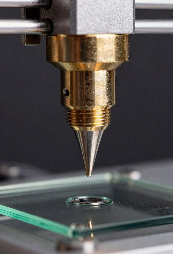
If you’ve ever watched a first layer peel up and wondered what went wrong, this is why.
Why it matters: if your nozzle-to-bed distance changes across the plate, the filament either squishes out too thin, won’t stick, or clogs the nozzle. For example, I once tried printing a large vase and the first 10 mm warped because one corner sat 0.4 mm higher than the rest; the print failed after four hours.
How probes help: they map the bed surface so your printer’s firmware can adjust the Z height as the nozzle moves. For instance, a BLTouch measured a dip of 0.15 mm near the center of my plate, and the mesh compensation raised the nozzle there so the filament laid down flat.
What to check before printing:
- Measure a few points manually with feeler gauges or a sheet of paper; if gaps vary more than 0.2 mm, take action.
- Run your probe’s mesh grid—try 3×3 for quick checks, 7×7 for larger beds.
- Save the mesh to EEPROM if your firmware supports it so you don’t re-probe every job.
Types of probes and a quick comparison: mechanical probes like microswitches are simple and cheap but can wear; inductive or capacitive sensors detect metal and need calibration for different bed surfaces; optical and BLTouch-style probes work across surfaces with more consistency. I swapped an inductive probe for a BLTouch when I changed from a glass bed to PEI, and it removed frequent false triggers.
When you probe, do this:
- Heat the bed and hotend to your print temperatures—thermal drift changes distances.
- Disable any Z endstop offsets, then run the probe routine.
- Check the first layer after probing and adjust Z-offset in 0.05 mm steps if needed.
Practical numbers to remember: aim for a first-layer thickness of about 0.2–0.25 mm on a 0.4 mm nozzle, and keep bed height variation under 0.2 mm across the build plate for reliable adhesion.
If you follow those steps, you’ll get more consistent first layers and fewer failed prints.
How to Choose: Accuracy, Speed, Bed Material, EMI, Install Effort
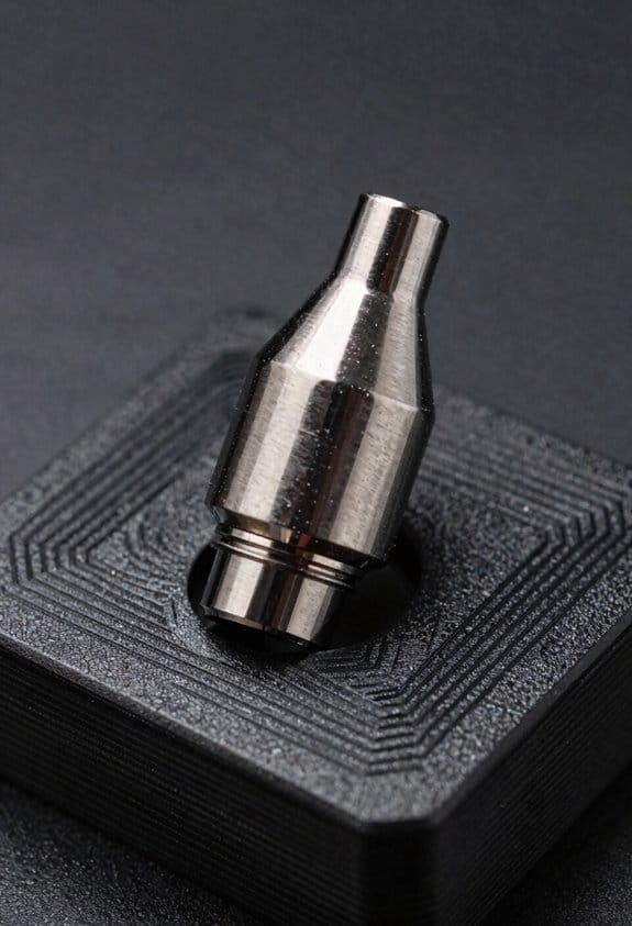
Before you pick a probe, know why it matters: a bad probe makes your first layer and mesh useless and wastes hours of print time.
Think of accuracy like a ruler for your nozzle height: more precise probes read within 0.01–0.05 mm while faster, cheaper probes are ±0.1–0.2 mm. For example, a BLTouch often gives repeatable 0.02–0.05 mm results on painted or textured beds, while cheap capacitive sensors can jump by 0.1 mm on different surfaces. If you want crisp top layers and tight tolerances, choose a probe that claims ±0.03 mm repeatability and plan for slower probing (0.5–1.5 seconds per point).
You’ll trade speed for precision, and here’s how to think about that: speed matters when you probe many points because total time scales with points × time per point. Example: 25-point mesh at 1 s/point adds 25 seconds, at 0.2 s/point it’s 5 seconds. If you want faster probing, reduce points to 9–16 or use a probe with <0.2 s response time.
Before you decide, check bed material compatibility because some sensors fail on glass or PEI. Real-world example: inductive probes work well on stock steel spring sheets but won’t trigger on plain glass; people using glass beds swap to BLTouch or a capacitive sensor tuned per surface. Steps to verify:
- Identify your bed material (e.g., glass, PEI, magnetic steel).
- Look up the probe’s compatibility for that material.
- Test-trigger the probe with the actual bed before final mounting.
You need to manage thermal drift because sensors shift as the bed and probe warm. Why this matters: drift changes your Z-offset mid-print and ruins first layers. Example: an inductive probe near a heated bed might shift 0.02–0.1 mm over the first 10 minutes of heating. Quick fix steps:
- Heat the bed to printing temperature for 10 minutes.
- Re-check Z-offset and probe trigger height.
- If drift >0.05 mm, move the probe farther from the heater or choose a sensor rated for high temp.
EMI can corrupt inductive and capacitive probes; placement and wiring matter. You’ll see false triggers if the probe is near stepper motor wires or the hotend heater cartridge. Example: a probe mounted on the X carriage next to motor wires produced noisy readings only when moving at high speed. Prevent it by:
- Routing probe cables away from stepper and heater wires.
- Adding a grounded shield or ferrite bead to the probe cable.
- Testing probe readings while moving the carriage at max speed.
Install effort varies a lot; match the install to your skills and gear. For example, installing a BLTouch needs one PWM or Z-min input and a secure mounting bracket, while an inductive probe often requires a metal mounting plate and precise spacing. Installation steps (general):
- Choose a mount location at least 10–20 mm from motors and heater blocks.
- Secure the probe so its sensing face is parallel to the bed.
- Wire the probe following the manufacturer pinout, then test triggers at multiple heights.
Finally, balance everything by scoring what matters to you: accuracy (1–5), speed (1–5), bed compatibility (1–5), EMI resilience (1–5), and install effort (1–5). Example scoring:
- If you want precision prints and don’t mind effort, pick a probe scoring 5/3/4/3/3.
- If you want plug-and-play fast probing, pick one scoring 3/5/4/4/5.
Pick the probe that matches the highest two scores you care about, then follow the specific test steps above to verify performance on your machine.
Recommended Products

Next-Gen Multicolor 3D Printer: The Creality K2 Pro Combo 3D printer supports up to 16 colors and multi-material printing with 4 Creality Filament System (CFS) units. As a true multi color 3d printer, CFS delivers auto filament identification, relay printing, moisture-proof storage, and real-time temp & humidity display. Combined with Creality OS and Creality Print, users get seamless multicolor slicing and smart filament management for a next-generation printing experience. (K2 Pro Combo comes with one CFS unit. Additional CFS units sold separately. Creality K2 Pro Hardened Steel Nozzle *1 (Additional Bonus)

This 3-coordinate XYZ axis CNC probe is designed for wide DIY CNC applications, like fast zero-point acquisitions, surface flatness acquisition, measuring workpiece geometries such as edges, holes, grooves, studs, angles and corners, workpiece scanning & digitizing. ( Tips: It's developed for DIY applications, not recommended for industrial use.)
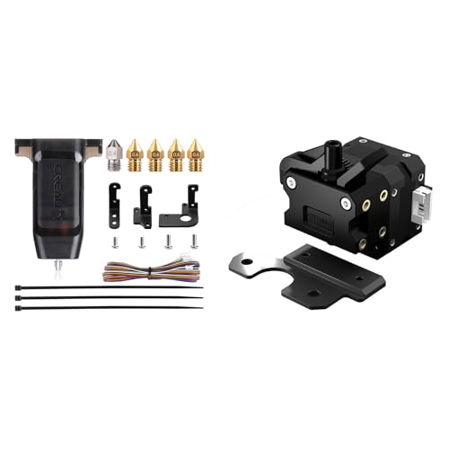
Creality 3D Printer Auto Bed Leveling Kit - The Creality cr touch auto bed leveling kit fulfilled simple structure and high precision. Performs multi-point detection on the printing platform and records the height of each detection point. Stable quality, long service life, and can be reused more than 100,000 times.
Inductive Probes: How They Work, Strengths, Failure Modes
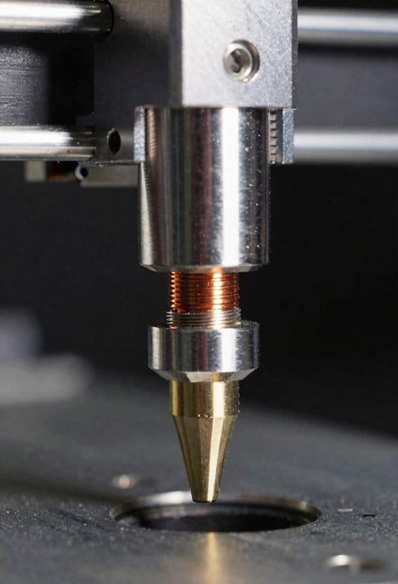
If you’ve ever wondered why a probe sometimes misses a bed, this is why.
Why it matters: you need reliable bed sensing so your first layer isn’t a ruined print. In practice, an inductive probe detects a metal bed by creating a changing electromagnetic field and sensing how a nearby conductive surface alters that field.
How it works (one real example): put the probe 5 mm above a steel plate and move the plate under the probe; when the plate is within the probe’s sensing distance the controller sees a switch. The probe’s coil is driven at a frequency (typically 100 kHz to 1 MHz for hobby probes) that induces eddy currents in the metal; those currents generate their own magnetic field that reduces the coil’s effective inductance and amplitude, and the sensor electronics detect that change and flip an output.
Strengths — why you might choose one:
- Speed: you can probe a point in under 50 ms, which is much faster than many mechanical switches.
- Non-contact: you won’t wear a tip by touching the bed.
- Repeatability on steel: when mounted rigidly 30–50 mm from the nozzle and used with a plain steel bed, you can expect trigger-height variation under 0.05 mm between probes.
Real example: on a Prusa-style steel spring sheet, an inductive probe mounted 10 mm behind the nozzle gave consistent Z triggers across the plate within 0.03 mm.
Failure modes — what can break things:
- Material limitations: they won’t detect glass, most ceramics, or common plastics because those materials don’t support induced currents; for a glass print bed you need a capacitive probe or a mechanical switch.
- EMI and wiring: close motors, heater wiring, or unshielded cables can shift trigger height by 0.1–0.5 mm; keep the probe cable routed at least 20 mm away from stepper motor cables and use twisted-pair or shielded cable when possible.
- Mounting and coatings: ferrous paint, thick plating, or a steel mount between the probe and the bed can change sensing distance; if your mount uses a 1 mm thick steel plate, expect the sensing point to move by a similar fraction of the probe’s normal sensing gap.
Real example: a Creality with a small inductive sensor mounted inside an aluminum bracket showed trigger changes of ~0.2 mm when the bracket was swapped for a steel one.
Practical steps to avoid problems:
- Position: mount the probe where the distance to the nozzle is stable; measure and record the probe-to-nozzle offset.
- Cable routing: keep the probe cable at least 20 mm from stepper and heater wires; use shielded cable and ground one end.
- Test materials: print a 20 mm tall calibration column and probe at several spots; if readings vary more than 0.1 mm, check wiring and mounting.
- Alternative: if you print on glass or magnetic PEI, switch to a capacitive probe or use a BLTouch style mechanical sensor.
Quick numbers to remember: typical sensing frequencies 100 kHz–1 MHz, expected repeatability on plain steel under rigid mounting ~0.03–0.1 mm, and keep probe cable 20 mm from noisy wires.
If you follow those steps you’ll avoid most common failures.
Recommended Products

Function: The three-coordinate probe can realize quick centering, edge finding, center finding, shape measurement and other functions by connecting the CNC to the knife edge

Genmitsu Wireless Automated Z-Axis Tool Setting: The Genmitsu Z-axis probe enables your CNC machine to automatically find the surface zero point within 0.02mm accuracy, guaranteeing perfect first-layer results every time Z-Probe Kit

Suitable for processing woodworking, acrylic, plastic, aluminum, iron, steel, etc.
Capacitive Probes: Operation, Best Beds, Environmental Limits
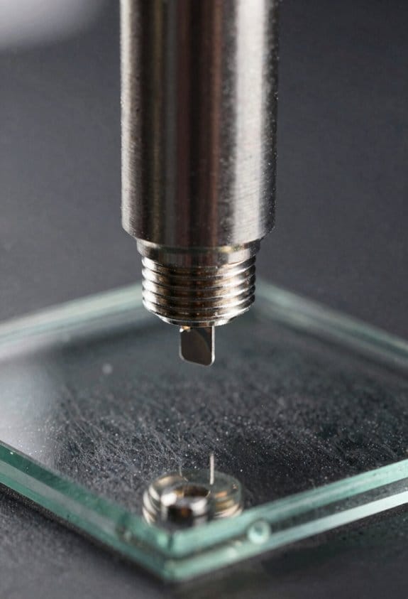
If you’ve ever fiddled with a printer trying to get the first layer perfect, this is why capacitive probes matter: they detect nozzle-to-bed distance without touching the bed, so you can avoid scratching a finished surface.
Capacitive probes work by measuring tiny changes in an electric field between the sensor and the build surface, and that matters because your Z-trigger moves the nozzle to the exact start height for good first-layer adhesion. For example, when I switched from manual paper-leveling to a capacitive probe on an aluminum bed, I cut first-layer warp in half on PETG prints. The probe senses dielectric differences as the nozzle approaches and triggers when the field shifts.
Why you’d pick one: they can sense many materials, including some plastics and coated glass, because they detect dielectric change rather than relying on physical contact. A real-world case: if you’re printing on a PEI sheet with a thin polycarbonate part stuck on top, the probe still finds the right Z height where an inductive sensor would fail.
Which beds work best and why that matters: pick beds with consistent dielectric properties so your trigger point is repeatable. Examples that work well: aluminum sheets, PEI on spring steel, and plain uncoated glass when you use consistent tooling. Avoid beds with uneven coatings or mixed materials—if the surface has patches of adhesive or uneven paint, your trigger can shift by 0.05–0.2 mm between points.
Steps to set up and keep a stable trigger:
- Mount the probe about 2–4 mm from the nozzle horizontally so physical collisions are unlikely.
- Set your probe sensitivity according to the manufacturer’s spec; start in the middle of the range and test.
- Run a Z-probe calibration sequence: move the nozzle to several points across the bed and record trigger heights; expect variation under 0.1 mm on a good setup.
- Recalibrate whenever you change the bed surface, heater, or ambient conditions.
Environmental limits and what to watch for: capacitive probes drift with temperature and humidity, and that matters because drift changes where your nozzle thinks “zero” is. On humid days or after long heat cycles, expect trigger shifts up to 0.2–0.3 mm unless you recalibrate. For example, after turning on a 60 °C bed, do one calibration pass once the bed reaches temperature; the probe reading can move as the aluminum expands.
Practical tips to reduce noise and keep repeatability:
- Keep the bed at printing temperature during calibration.
- Avoid placing metal objects near the probe; they change the field.
- If humidity is high (>60% RH), run a quick Z-check before starting long prints.
- If you see drift, increase recalibration frequency to weekly or before critical prints.
Capacitive probes are non-contact, so wear is low and you won’t abrade your print surface, but they require more environmental care than contact probes. A stable setup gives you repeatable first layers within about 0.05–0.1 mm once you follow the steps above.
Recommended Products

【200mm/s Max Speed】Flsun Super Racer offers a maximum printing speed of 200mm/s, significantly boosting speed while upholding printing quality, thereby saving 50% time compared to other printers

ANTCLABS BLTouch : Auto Bed Leveling Sensor/to be a Premium 3D Printer (with 1M Extension Cable Set)
BLTouch is an auto leveling sensor for 3D Printers based on open-source.

Compatible: This CR touch fits for Creality Ender3 v2/Ender3/Ender3 Pro/Ender5/Ender5 Pro/CR-10 with 32 bit v 4.2.2(4.2.7) mainboard. Notice:Just for 32 bit motherboard printers.
Strain‑Gauge & Load‑Cell Probes: Direct Force Sensing Advantages
If you’ve ever bed‑leveled a printer and gotten inconsistent first layers, this is why.
Why it matters: measuring actual force at the nozzle means your printer reacts to physical contact, so your first layer will be consistent across different bed materials. For example, I swapped from textured PEI to glass and kept the same trigger height because the probe senses force, not surface properties.
How strain‑gauge/load‑cell probes work and why you’d pick one
Why it matters: force sensing detects contact on any material, so you don’t have to change settings when you change beds. Imagine printing a calibration skirt on a fresh glass plate and seeing identical nozzle height as when you used a PEI sheet.
- They measure the tiny downward force when the nozzle touches the bed, not electromagnetic changes.
- Because they sense contact directly, glass, PEI, and metal all behave the same.
- You’ll get fewer material‑dependent errors when switching build surfaces.
Installation and calibration steps
Why it matters: if you don’t set the trigger threshold, the probe will either miss touch points or fire too early, ruining first layers. In one build I installed a load‑cell under the hotend and set the trigger to 0.2 N, which produced perfect first‑layer squish with 0.2 mm layer height.
- Mount the probe solidly to the carriage using the manufacturer’s bracket; torque screws to the specified value (typically 2–3 N·m).
- Power the printer and open your control interface.
- Run the probe calibration routine: with nozzle above the bed, command the probe to zero, then lower the nozzle slowly until it barely deflects and record the reading.
- Set the trigger threshold (start at 0.1–0.3 N for Bowden setups, 0.2–0.5 N for direct drive) and save.
- Print a single‑layer test (20 mm square, 0.2 mm height) and adjust by +/-0.05 N if the squish is too much or too little.
Dealing with vibration and false triggers
Why it matters: unwanted triggers from vibration will misplace Z home and ruin prints, so you need to minimize noise. I reduced probe false positives by lowering probe speed from 10 mm/s to 4 mm/s and retesting.
- Slow probing speeds help: try 3–6 mm/s for the probe move.
- Use soft acceleration on probing moves (e.g., 50–200 mm/s²).
- Improve mounting isolation: add a 0.5–1 mm rubber washer or thin silicone pad between the probe and bracket if the design allows.
- Make sure the rest of the toolhead is tightened; loose fans or ducts transmit noise.
Maintenance and repeatability
Why it matters: periodic checks keep your trigger consistent so old calibrations still work. On one printer I check the force zero monthly and after any crash; that prevented a batch of failed prints.
- Check zero: with nozzle off the bed, verify the probe reads zero or adjust the offset.
- Reconfirm trigger threshold after any mechanical change (new mount, replaced screw, swapped nozzle).
- Every 3–6 months, run the 20 mm single‑layer test to confirm first‑layer behavior.
Quick troubleshooting checklist
Why it matters: a short list gets you back to printing fast when something’s off. I use this exact checklist whenever a first layer looks wrong.
- If Z homes too high: lower trigger threshold by 0.05–0.1 N.
- If Z homes too low or drags: raise threshold by 0.05–0.1 N.
- If probe triggers intermittently: reduce probing speed and check mounts.
- If readings drift over time: check for loose screws and retest zero.
Final practical tip
Why it matters: the right balance of stiffness and isolation keeps readings clean and repeatable. Use a firm mechanical mount for alignment and a thin isolation pad (0.5 mm silicone) to cut high‑frequency vibration without introducing flex.
Physical Contact Probes (BLTouch Style): Durability vs Speed Trade‑Offs
Think of a probe like a tiny hammer that taps your bed to find height.
Although BLTouch‑style probes rely on a small mechanical pin, you should know this matters because they trade long‑term durability for probing speed in ways that affect daily prints. I use them because they work on glass and tape, they trigger reliably via a Hall effect sensor, and they tolerate many bed materials. Check the pin every few hundred hours; pin wear is rare but possible after thousands of cycles, and replacing the pin takes about 5 minutes with a small screwdriver.
Before you probe a mesh, know why deployment latency matters in one sentence: the probe must extend and retract, which slows multi‑point probing and raises cycle time. Deployment adds roughly 0.2–0.6 seconds per probe cycle depending on firmware and mount geometry, so a 25×25 mesh can take 10–30 seconds longer than with a non‑contact sensor. For example, when I switched from a capacitive sensor to a BLTouch on my Prusa‑style bed, a 9×9 mesh went from 18 seconds to about 30 seconds because of the extend/retract time.
Why you might still pick one comes down to surface independence in one sentence: mechanical probes work on bare glass, PEI, and painters tape without tuning. For example, if you print on a glass sheet and a part shifts slightly, the BLTouch still triggers where a capacitive probe would fail, and that saved me a failed first layer on a glossy part. If you’re a hobbyist who prints 1–3 times per week, the small speed hit is usually acceptable, especially if you plan simple maintenance.
How to maintain one so it lasts in one sentence: inspect, clean, and replace the pin on a schedule. Steps:
- Every 100–200 printing hours: wipe the probe pin with isopropyl alcohol to remove filament dust.
- Every 500–1,000 hours: visually inspect the pin for bend, burrs, or flattening; hold it at eye level against a straight edge.
- If any wear appears or triggers become inconsistent: replace the pin (5 minutes) or swap the probe for testing.
If you want faster meshes without losing surface coverage, know this in one sentence: you can reduce probe count or use hybrid strategies. For example, run a 5×5 mesh for fast daily checks and a full 25×25 mesh only when you change beds or after a crash. That cuts probe time from minutes to under 30 seconds on many setups.
In short, you’ll trade a bit of speed for reliable triggering across different bed surfaces, and you can manage longevity with a handful of simple checks.
Real‑World Performance & Best Picks by Bed Type and Budget
Before you pick a probe, know that bed material and budget change which sensor gives you reliable Z‑touch in real prints.
If you use a metal bed, go inductive for speed and simplicity but plan for EMI and firmware filtering. For example, on a Prusa-like steel sheet you’ll get repeatable triggers at 1–2 ms cycles if you wire the sensor away from stepper cables and enable a 10–20 ms debounce or a moving‑average filter in your firmware. Use short, shielded cable runs. Shielding reduces false triggers.
Glass or PEI beds need probes that measure force or contact, because surface aging and conductivity confuse proximity sensors. A real‑world case: a PEI sheet with scratches and glue residue made my inductive probe miss Z by 0.1–0.2 mm; switching to a strain‑gauge probe removed that drift. Install strain gauges so the probe head touches the bed at ~0.5–1.0 mm speed and set firmware trigger height accordingly.
Capacitive sensors sit between those options and work on some non‑metal surfaces if you tune them for your environment. For example, a capacitive on a 3 mm glass with PET tape required adjusting sensitivity and adding a 5–10 mm offset to ignore bed flex when heated. Expect to re‑calibrate if you change bed covering or ambient humidity.
On tight budgets, BLTouch‑style probes give broad compatibility for modest cost but have slower cycles. Example: a BLTouch probe on a budget printer took ~25–35 ms per probe compared with 5–10 ms for a good inductive sensor; plan longer mesh runs or use fewer probe points (e.g., 9 points instead of 25) to keep probing time reasonable.
For high precision and low maintenance, expect to pay more for strain gauges or MicroProbe setups, but you’ll get better repeatability. In practice, a MicroProbe rig reduced my mesh variance from ±0.08 mm to ±0.03 mm over a month of printing. Budget for a sturdier mount and a proper firmware debounce of 2–5 ms to get that performance.
Recommended Products


Necessary spare part for SV08: hot bed leveler tool, responsive and can accurately detect the height of the print bed surfaces. Cylindrical induction head: 12mm, Detection mode: inductive, Detection distance: 2mm±10%

Achieve Consistent First Layers: This auto leveling sensor assists in establishing a uniform distance between the nozzle and the print bed across the entire surface, contributing to reliable initial layer adhesion for your 3D prints.
Frequently Asked Questions
Can Probes Compensate for Warped or Uneven Heater Elements?
Yes — they can partially compensate for warped or uneven heater elements by mapping topology, but compensation limits exist; I’ll warn you that sensor drift and probe type affect long-term accuracy, so periodic recalibration’s necessary.
How Do Probes Affect Multi-Extruder Bed Alignment?
I’ve seen twin-nozzle chaos become precise: I map each tool’s nozzle offsetting, probe hysteresis noted, then apply per-extruder offsets and mesh compensation so each nozzle prints aligned, trading a quick calibrate for consistent multi-extruder accuracy.
Are Probe Recalibrations Needed After Firmware Updates?
Yes — I usually recommend firmware dependent recalibration after major updates, though EEPROM retention can preserve offsets; I’ll check settings and force a probe test to confirm sensors and Z-offsets stayed correct.
Do Probes Interfere With Auto Bed Heating Cycles?
Yes — I’ve seen probes affected: heating cycles introduce thermal noise and can cause sensor drift, so I’d recheck or recalibrate after warmup, especially for capacitive or inductive types sensitive to temperature shifts.
Can Bed Probing Damage Delicate Build Surfaces Over Time?
Absolutely — I think probing can slowly cause surface wear and probe abrasion, but with gentle probes, proper offsets, and fewer touch points you’ll avoid catastrophic damage; I’d monitor and replace fragile sheets periodically.