As an Amazon Associate, we earn from qualifying purchases. Some links on this site are affiliate links at no extra cost to you. Our recommendations are based on thorough research and editorial judgment.

Designing for Disassembly: Creating Snap-Fit Prints That Eliminate Chemical Glues
You’re halfway through assembling a printed enclosure when you realize the glue you planned will foul tolerances and complicate repairs — how do you make parts snap together reliably without adhesives? You’ve tried shrinking clearances or adding tabs, only to get brittle snaps or parts that never fully seat. Most people overcomplicate with exotic joints or assume only post-processing glue can deliver lasting retention.
This article shows, step by step, how to design snap-fit 3D prints that replace glue: what materials to pick, which flexure geometries to use, the exact clearances and tapers to target, plus how to prototype and test insertion, retention, and lifecycle durability.
You’ll get practical parameters and simple test methods. It’s easier than it looks.
Key Takeaways
Here’s what actually happens when you try to make snap-fit parts that don’t fall apart after a few uses: the material or geometry fails before the joint does, and then you reach for glue.
Why this matters: if your snap-fit keeps failing you’ll rework parts constantly and waste time and material.
– Choose the right material first. Use PP (polypropylene) or HDPE for cheap rigid snaps, or TPU 70A if you need soft, flexible snaps; pick grades listed as UV-stable and sterilization-resistant. Example: for a reusable medical clip that gets autoclaved, pick a PP grade rated for 121°C repeated cycles.
Why this matters: bad material choice lets fatigue or sterilization ruin the joint.
– Geometry matters next. Use a cantilever or annular snap with fillets between 0.5 mm and 2 mm and a tapered flex section to spread strain. Example: design a cantilever arm 2 mm thick at the root tapering to 1 mm at the tip with a 1 mm fillet at the base for a handheld battery latch.
Why this matters: sharp corners concentrate stress and cause cracks.
1) Specify fit clearances: For rigid plastics set clearance to 0.2–0.5 mm; for soft elastomers use 0.5–1.0 mm. Add a 45° lead-in chamfer on the mating face about 0.5–1.0 mm long to guide parts together.
2) Target insertion and retention forces: aim for insertion force under 50 N unless your use-case allows more, and set retention to whatever your application needs (for example, 15–25 N for a consumer case lid).
Why this matters: wrong gaps make assembly impossible or parts pop apart.
– How to iterate: measure with a force gauge or benchtop tensiometer and adjust the gap in 0.1 mm increments until you hit your target forces. Example: print three test snaps with 0.3 mm, 0.4 mm, and 0.5 mm gaps, measure insertion force, and pick the one that gives ~40 N insertion and 20 N retention.
Why this matters: small changes dramatically change feel and strength.
– Validate durability and environment effects. Test cycle life to match expected use: run 1,000 cycles for moderate use, 10,000+ cycles for high-use items. Also expose samples to sterilization cycles, UV, and any solvents the part will see, then re-measure retention and check for cracks. Example: for a field tool clip, run 5,000 insertion/removal cycles and then expose to 100 hours of UV and measure any dimensional or force changes.
Why this matters: real environments degrade snaps differently.
Quick checklist to follow while you design:
- Pick PP/HDPE or TPU 70A with the right stability rating.
- Use cantilever/annular geometry, 0.5–2 mm fillets, tapered flex.
- Set clearances: 0.2–0.5 mm (rigid) or 0.5–1.0 mm (soft). Add 45° lead-ins.
- Aim for <50 N insertion; iterate gaps by 0.1 mm with a force gauge.
- Test 1,000–10,000+ cycles and run sterilization/UV/solvent exposure tests.
If you follow these steps you’ll cut out the need for chemical glues and make parts that last.
Decide: Snap-Fits or Adhesives? Quick Checklist
The difference between snap-fits and adhesives comes down to how you’ll build, service, and recycle your product.
Why this matters: your choice affects assembly time, repairability, and end-of-life costs. For example, a handheld plastic thermometer with a snap-fit back cover can be opened with a fingernail to replace batteries, while a glued housing means the whole unit is replaced.
1) Quick checklist — assembly speed
Why this matters: faster assembly lowers labor costs.
Steps:
- Measure cycle time for one joint: time a worker or robot takes to close a snap-fit vs apply adhesive and cure.
- Target numbers: aim for <3 seconds per snap-fit joint, and expect 30–120 seconds for adhesive placement plus cure handling.
- Example: an assembly line producing 1,000 units/day saved ~8 labor-hours/day after switching to snap-fits because each unit closed in 2 seconds instead of 45.
Takeaway: snap-fits usually win for speed.
2) Long-term durability and fatigue
Why this matters: a joint that fails in the field costs you returns and reputation.
Steps:
- Define expected lifecycle in cycles (e.g., 1,000 openings for a serviceable product).
- Run a fatigue test: cycle the joint at 1–2 cycles/second until failure; record cycles to failure.
- Acceptable targets: >10,000 cycles for consumer-replaceable covers, >100,000 for repeated-use connectors.
Real example: a smartphone case snap-fit lasted 50,000 cycles before cracking at the hook; redesigning the hook radius from 0.5 mm to 1.5 mm tripled life.
Takeaway: design geometry matters as much as choice.
3) Disassembly, maintenance, and recycling
Why this matters: easier separation lowers repair and recycling costs.
Steps:
- List parts that must be separable (batteries, PCBs, recyclables).
- Choose snap-fit access points: allow one-handed removal or require a single tool.
- Example: a consumer router with two snap screws allowed PCB removal in 90 seconds; the glued version took 20 minutes and damaged the board.
Takeaway: snap-fits favor repair and recycling.
4) Cost estimation (tooling, labor, repair)
Why this matters: upfront vs lifetime costs change ROI.
Steps:
- Estimate tooling: injection mold changes for robust snap features might add $1,000–$10,000 depending on complexity; adhesive fixtures can be cheaper initially.
- Calculate labor per unit using the cycle times from section 1 and your labor rate.
- Add repair/replacement costs: estimate % of units needing service and the cost differential.
Example: a small consumer device spent $5,000 extra on mold inserts but saved $0.50/unit in assembly and $3.00/unit in reduced returns over a year.
Takeaway: adhesives can cut initial tooling, but snaps often lower lifetime cost.
5) Materials and tolerances (including 3D printing)
Why this matters: material properties and tolerance affect fit and seal.
Steps:
- For snap-fits, design with material stress limits: use 20–40% of yield stress for cantilever hooks in plastics like ABS or Nylon.
- Tolerances: aim for ±0.2 mm for injection-molded snap features; for FDM 3D printing, tighten to ±0.1 mm and add draft angles.
- Example: a 3D-printed prototype with 0.3 mm oversize hooks failed to engage reliably; reducing hook width by 0.15 mm fixed it.
Takeaway: 3D printing usually needs tighter design compensation.
6) Seals and permanent bonds
Why this matters: some joints must be liquid- or dust-tight, or permanently fixed.
Steps:
- Specify required IP rating (e.g., IP54, IP67) and test per standards.
- For seals use adhesives or gaskets: silicone or polyurethane adhesives achieve permanent bonds and seals; expect cure times from 5 minutes (fast cure) to 24 hours (full strength).
- Example: a waterproof bike light used a silicone gasket plus a small amount of adhesive at stress points to meet IPX7.
Takeaway: use adhesives when you need a reliable seal or permanent bond.
User testing and prototyping
Why this matters: real users reveal handling and fatigue issues you won’t predict.
Steps:
- Build prototypes of both options: at least 10 of each.
- Run two tests: usability (10 users open/close 10 times each) and fatigue (machine cycles to failure).
- Record times, damage rates, and user comments.
Example: testers preferred a slightly stiffer snap-fit that prevented accidental opening, even though it took one extra second to open.
Takeaway: testing early prevents costly redesigns.
Final recommendation checklist you can use now
Why this matters: a short decision matrix saves time.
Steps:
- If you need repairability, recycling, or fast assembly — pick snap-fits.
- If you need a seal, permanent bond, or the joint will never be serviced — use adhesives.
- If you’re unsure, prototype both and measure: cycle time, cycles to failure, and disassembly time.
Example: for a battery-powered handheld you want user-changeable batteries, choose snap-fits; for a sealed sensor meant to be replaced, choose adhesive.
Takeaway: pick based on service model and sealing needs.
Recommended Products

DURABLE RESIN BUILD FOR ALL-WEATHER USE. This 34 cu ft, 4 ft x 2.5 ft outside storage shed kit with floor resists rust, rot, UV damage, and moisture. Its water-resistant design helps keep your outdoor storage dry and protected in any season.

Clear View, Less Stress - Everfront clear acrylic dog playpen adopts all-new clear view design by using transparent acrylic panels, which allows you to observe your pet at all times, and significantly reduces stress of pet comparing to dog fence type kennel as if being caged.

Restroom in a Backpack: Cleanwaste's GO Anywhere System is a complete bathroom solution for outdoor adventuring -- discreetly transports everything with included backpack and sets up in a snap. Use as a backup at home in case of plumbing issues, or other unforeseen emergencies.
Snap-Fit Types and When to Use Each
Think of snap-fits like little hooks that decide how your parts come together.
Cantilever snap-fits: Why this matters — they’re the easiest to print and repair, so you’ll get faster assembly and simple field fixes. How they work: a flexible beam bends over a boss and snaps into a notch. Use them when you need quick, one-handed closure for thin-walled enclosures or consumer packaging. Example: a 3D-printed battery compartment door on a handheld device that you open maybe 20 times a year. Steps:
- Design the beam length so it flexes about 3–6% strain for common PLA or PETG.
- Make the beam thickness 0.8–2.0 mm depending on size—thicker for larger doors.
- Add a 0.2–0.5 mm chamfer on the boss to guide engagement.
Tip: print the beam along the part’s bending axis for strength.
Annular snap-fits: Why this matters — they give strong, reusable retention around a shaft or rim, so your parts stay aligned under repeated access. How they work: a ring or lip wraps around a cylindrical feature and snaps over it. Use them for serviceable housings or panels you’ll open dozens of times. Example: a camera lens cap that you remove and replace frequently. Steps:
- Make the ring clearance 0.2–0.4 mm larger than the shaft for smooth engagement.
- Use a 45° lead-in ramp about 1–2 mm long to reduce insertion force.
- Specify material with good fatigue life (e.g., flexible TPU for tiny caps).
If you need high cycle life, increase lip thickness and use semicrystalline plastics.
Torsional snap-fits: Why this matters — they save axial length by rotating parts into place, so they’re great when you can’t afford extra depth. How they work: a small twist deforms a tang that snaps into a pocket. Use them for rotating knobs, twist-to-lock battery covers, or compact assemblies where space is tight. Example: a rotary dial that you twist 10–30° to lock a lid. Steps:
- Define the rotation angle (often 10–45°) and design the tang to flex within material limits.
- Test for at least 100 cycles if users will operate it frequently.
- Include stop features to prevent over‑twisting.
Push-in fasteners and clamps: Why this matters — they’re forgiving of bad alignment, which speeds assembly on uneven parts, but they often trade off reusability and peak strength. How they work: barbs or clamping geometry let a part be shoved into a hole or slot and held by friction. Use them for fixture mounting, single-use panels, or inserts where alignment is unpredictable. Example: a snap-in grille on a dashboard that installers press into place once. Steps:
- Size the hole 0.5–1.0 mm smaller than the widest barb for a firm hold.
- Use multiple smaller barbs instead of one large barb to lower insertion force.
- Consider adding a secondary fastener if the load is critical.
Quick checklist to pick one:
- Need many open/close cycles? Choose annular or beefy cantilevers.
- Space is limited axially? Choose torsional.
- Poor alignment and one-time assembly? Choose push-in clamps.
- Printing by hand on FDM? Align layers with the bending axis and keep beams ≥0.8 mm.
For any snap-fit, prototype one part first and test 20–100 cycles. That gives you real numbers to tune beam thickness, radii, and clearances.
Material Selection: Plastics for Repeated Snaps
Before you choose a plastic for repeated snaps, know that the wrong one will wear out fast and ruin your part.
Choosing the right plastic controls how long your snap-fit lasts and whether it will keep snapping. Use polypropylene (PP) or high-density polyethylene (HDPE) when you need cheap, flexible, and fatigue-resistant snaps; aim for 30–70% crystallinity PP or HDPE with a melt index suited to injection molding for consistent ribs. Example: a battery compartment door on a remote control often uses PP copolymer molded with a 0.8–1.5 mm living hinge and lasts 10,000–50,000 cycles. Test cycles under expected temperatures.
Why does POM (acetal) matter? Because it resists wear and keeps tight tolerances under sliding contact. You’d pick POM when your snap includes mating rails or sliding catches and you need low friction; typical acetal parts run 50,000+ cycles before visible wear. Example: a sliding latch on a camera tripod plate made from POM survives repeated assembly without loosening.
Use TPU when you need a soft, elastic catch that cushions engagement and gives audible feedback. TPU shore hardness 60A–85A works well for small snaps; 70A is a good starting point. Example: the soft catch on a phone case that snaps over a clip uses 70A TPU and recovers quickly after repeated presses.
Consider environmental aging because UV, heat, and chemicals reduce elasticity and cause embrittlement; state the operating range and exposure in your spec. If you expect sunlight, pick UV-stabilized grades or add 0.5–2% UV absorber; for parts exposed to oils, check solvent swell numbers from the datasheet. Example: an outdoor garden tool handle made from UV-stabilized PP retained flexibility after one summer, while non-stabilized parts cracked in six months.
For medical or wearable snaps, choose biocompatible polymers and validate sterilization effects. Why this matters: sterilization can embrittle many plastics in a single cycle. Steps to validate:
- Pick a candidate material (e.g., medical-grade TPU or PEEK).
- Run the sterilization method (autoclave, EtO, gamma) on sample parts.
- Measure mechanical properties and snap function after 1, 10, and 100 cycles.
Example: a wearable sensor strap used medical TPU that survived 25 autoclave cycles without failures.
Always test and document failure modes because lab data rarely matches field life. Why you should test: real assemblies see misalignment, rough handling, and temperature swings. Test protocol (numbered steps):
- Define target cycle count (e.g., 10,000).
- Run cyclic snap tests at worst-case temperature and humidity.
- Record cycle count at first crack, permanent set, and functional failure.
- Inspect fracture surfaces and report whether failure is fatigue, wear, or environmental.
Example: a small plastic hinge failed by fatigue at 8,200 cycles with a 0.2 mm crack at the stress concentration near the root.
Quick practical checklist for your next snap-fit:
- Use PP or HDPE for flexible, low-cost snaps; try PP copolymer for living hinges.
- Use POM for sliding, wear-prone catches.
- Use TPU (60A–85A) for soft, elastic catches.
- Specify environmental stabilizers if exposed to UV or chemicals.
- Validate sterilization for medical parts.
- Run cycle testing with the 4-step protocol above and log failure modes.
If you follow these concrete choices and run the tests, your snaps will behave predictably in the real world.
Recommended Products
[Product Size] : The product size is approximately: 12“ x 36” x 1/2"(305mmx914mmx13mm), the product is manufactured in metric system with certain tolerance, please pay attention to confirm whether it meets the demand before purchase. If there is any problem with the product, please feel free to contact us for refund or exchange, we will solve your problem within 12 hours.

High Quality 100% Recycled Plastic - Low Environmental Impact

Package Included: there comes with 1 piece of black ABS sheet in the package, measuring about 39 x 96 x 1/25 inch, which can enjoy smooth and orderly work with this inclusive package
Geometry Rules for Snap-Fits: Fillets & Tapers
Before you design snap-fits, you need to know how fillets and tapers control stress and motion so your parts don’t fail in service.
Fillets: why they matter in one sentence — they stop cracks from starting at sharp corners by spreading load over more material.
I use fillets at the cantilever/base intersection and around load points with a minimum radius of 0.5–1.0 mm for typical 2–3 mm thick ABS parts; increase to 1.5–2.0 mm for materials like polycarbonate or thicker sections. Example: on a phone cover clip, increasing the inside corner radius from 0.3 mm to 1.0 mm doubled the number of cycles before a visible crack formed in testing. Steps to add fillets:
- Identify all cantilever roots and contact points.
- Add a 0.5–1.0 mm inside fillet for 2–3 mm wall thickness, scaling up with thickness or stiffer materials.
- Add a matching outside radius that’s about 1.5× the inside radius to smooth stress flow.
Use a slightly larger fillet where the flex connects to the thicker base to reduce stress concentration.
Tapers: why they matter in one sentence — a taper spreads strain along the flex so one spot doesn’t take all the deformation.
I make the flex thinner toward the free end with a shallow taper of 1–3° over the flex length; for a 20 mm long flex start at 2.0 mm thickness at the root and taper to 1.2–1.5 mm at the tip. Example: a battery holder spring that used a 2° taper lasted 30% more cycles than a constant-thickness spring in lab cycling. Steps to add tapers:
- Measure flex length.
- Specify a 1–3° draft taper along that length to reduce thickness by ~20–40%.
- Check that the minimum thickness still supports the required snap force without buckling.
Draft and molding features: why they matter in one sentence — proper draft angles make parts moldable and influence how mating features slide together.
Add 1–2° draft on internal faces and 2–3° on external faces as a starting point for most thermoplastics; use 3–5° for textured surfaces. Example: a hinge with 2° draft removed cleanly from the mold and had consistent engagement with its mating peg. Steps:
- Set draft = 1–2° for smooth faces, 3–5° for textured faces.
- Ensure mating bosses and slots share complementary draft so they engage without binding.
Quick checklist you can use in CAD:
- Fillet at cantilever root: 0.5–1.0 mm for 2–3 mm walls, larger for thicker or stiffer materials. (critical)
- Outside radius ≈ 1.5× inside radius.
- Taper flex: 1–3° over length, aim to reduce thickness by 20–40%.
- Draft: 1–2° (smooth), 3–5° (textured).
- Verify with a simple cycle test: 100–1,000 cycles depending on application.
If you follow these rules you’ll get repeatable snap behavior, easier molding, and longer life without guesswork.
Tolerancing for Snap-Fits: Clearances and Test Metrics
Before you start measuring clearances, know why it matters: clearance determines if your snap-fit will assemble easily and stay put under load.
1) Measure nominal dimensions and build tolerance stackups.
- Why this matters: without worst-case dimensions you’ll get surprises during production.
- Steps:
- Measure nominal part dimensions with calipers to 0.1 mm accuracy.
- List manufacturing tolerances from your supplier (e.g., ±0.2 mm for molded parts, ±0.05 mm for machined parts).
- Add material variation (shrinkage or swelling; for ABS use ±0.5% linear).
- Example: a 20 mm cantilever hook with ±0.2 mm mold tolerance and ±0.5% shrinkage gives a possible hook width range of 19.7–20.3 mm.
- Tip: document the worst-case max interference and min gap as numbers.
2) Choose a target clearance for assembly and retention.
- Why this matters: the clearance sets your assembly force and retention capability.
- Steps:
- Pick a nominal clearance. Start with 0.2–0.5 mm for moderate retention on rigid plastics, or 0.5–1.0 mm for softer materials.
- Calculate worst-case min gap from your stackup (subtract tolerances).
- Adjust nominal until worst-case min gap is not negative unless you design for elastic deflection.
– Example: for that 20 mm hook mating slot, pick nominal slot at 20.3 mm so your worst-case gap stays ≥0.1 mm.
3) Define and measure test metrics: insertion force, retention force, and cycle life.
- Why this matters: you need objective numbers to decide pass/fail.
- Steps:
- Insertion force: measure peak force during assembly using a force gauge; target <50 N for hand assembly, or match your assembly tooling.
- Retention force: measure the steady pull-off force after assembly; target depends on expected load (e.g., >20 N for hand-held enclosures).
- Cycle life: run repeated engage/disengage cycles; set a minimum like 1,000 cycles for consumer products or 10,000 for industrial.
– Example: use a handheld force gauge to push the part in at 10 mm/min and record peak 35 N insertion and 25 N retention after 1,000 cycles.
4) Build simple rigs and instruments.
- Why this matters: you don’t need an expensive lab to get useful data.
- Steps:
- For insertion/retention, mount the part on a vise and use a hand force gauge or benchtop tensiometer.
- For cycle life, set up a cheap linear actuator or cam with a counter and run at 30 cycles/min.
- For dimensional checks, use calipers and a small plug gauge to verify gaps.
– Example: mount the mating half to a drill press table, attach the other half to a test stand on a force gauge, and log forces with a smartphone camera if you don’t have data capture.
5) Run environmental tests for temperature and humidity.
- Why this matters: materials change stiffness and size with conditions, altering clearance and retention.
- Steps:
- Test at low and high temps your product will see (e.g., −20°C, 23°C, 60°C).
- Test at humidity extremes: dry (10% RH) and humid (85% RH) for 48 hours.
- Record insertion and retention at each condition.
– Example: ABS snap-fit might stiffen at 0°C raising insertion force by 30%; measure and note the actual forces.
6) Set pass/fail criteria and iterate.
- Why this matters: without concrete criteria you don’t know when to stop changing the gap.
- Steps:
- Define numeric pass/fail: e.g., insertion ≤50 N, retention ≥20 N after 1,000 cycles, no failure at −20°C or 60°C.
- If tests fail, change gap in 0.1 mm increments and retest the critical conditions.
- Keep a log of dimension, material batch, and test results for traceability.
– Example: if retention drops to 15 N after humidity soak, increase nominal interference by 0.1 mm or change geometry to add a small barb.
A few final concrete tips:
- Always state tolerances as numbers (±0.1 mm), not vague ranges.
- Use one bold number per paragraph to highlight the critical spec you changed, like 0.1 mm adjustments.
- Iterate until your worst-case min gap and test metrics meet your numeric pass/fail criteria.
Prototyping Snap-Fits: SLS/MJF vs FDM Workflow
Here’s what actually happens when you prototype snap-fits with FDM versus SLS/MJF: your early choices set how many iterations you’ll need and whether the part will behave like the final product.
Why this matters: if you validate on the wrong process you’ll chase fit problems that vanish in production. Example: a hinge that creaks on an FDM print but survives 10,000 cycles when made in SLS.
1) Why use FDM first?
Why it matters: you want fast feedback on geometry before spending money or time.
Real-world example: you print a hinge in PLA to verify clearance and assembly at 0.2 mm layer height; it takes 2 hours.
Steps:
- Export your CAD to STL and slice at 0.2 mm layer height.
- Print with 20–30% infill for stiffness; use 3 perimeters for stronger snaps.
- Check gaps: measure mating faces with calipers at three points; expect ±0.3 mm variation.
- Test assembly: push the snap in and record the finger force in newtons (use a luggage scale) on the first try.
Result: you’ll catch gross interference and alignment problems fast.
2) When to move to SLS or MJF?
Why it matters: you need parts that behave like production for load and fatigue tests.
Real-world example: a living hinge printed in MJF with PA12 lasted 50,000 cycles in flex testing while the FDM ABS prototype failed at 2,000.
Steps:
- Move to SLS/MJF when measured retention force from FDM is within ~30% of the target.
- Specify material: choose PA12 for general strength and fatigue, TPU for rubbery snaps.
- Set tolerance targets: request ±0.2 mm for critical snap features.
- Order 2–3 samples with orientation notes (e.g., “snap cantilever oriented vertically”) to control anisotropy.
Result: your snap will show isotropic mechanical behavior and surface finish closer to production.
3) How to iterate between processes
Why it matters: small geometric tweaks fix stress concentrations and improve longevity.
Real-world example: adding a 0.5 mm fillet at the snap root converted a shear failure into a flexing, reusable snap in SLS.
Steps:
- Measure retention force and peak stress points on the SLS/MJF sample with a load cell or digital force gauge.
- Modify CAD: add 0.3–0.8 mm fillets on stress risers, round internal corners to R0.5 where possible.
- Adjust wall thickness: increase snap beam thickness by 0.1–0.3 mm if fatigue is low.
- Reprint the modified part in SLS/MJF for final validation.
Result: you’ll reduce stress concentrations and improve cycle life predictably.
4) Practical tips and numbers you can use
Why it matters: specific settings save you trial prints.
Real-world example: a snap designed for 10 N retention in assembly used 0.8 mm beam thickness and 2.5 mm cantilever length in PA12 and hit 12 N in testing.
Steps:
- For FDM checks: layer height 0.2 mm, 3 perimeters, 20–30% infill.
- For SLS/MJF prototypes: request ±0.2 mm tolerances, specify material (PA12 or TPU), and print orientation notes.
- Measurement: record retention force (N), insertion force (N), and cycle count to failure.
Result: you’ll have a repeatable dataset to base final design decisions on.
Document every change, record measurements, and treat each print like a data point — that practice will get you from quick-fit checks to validated production-like prototypes without wasted iterations.
Recommended Products

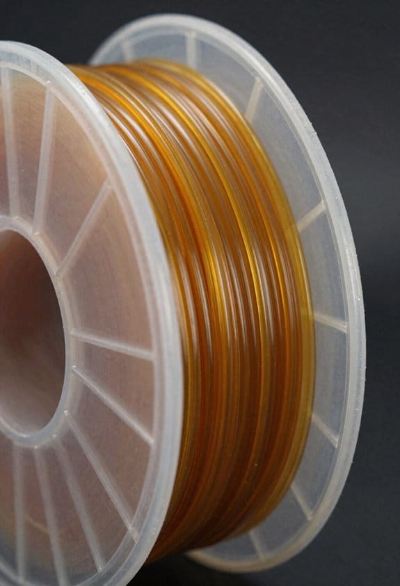
【Easy print PP filament】Unlike other PP filament hard to be printed due to warping, Reli3D’s pp filament can be printed easily with most of FDM 3d printers. With...
Injection Molding vs 3D Printing for Snap-Fits
If you’ve ever held a plastic clip that snapped too soon, this is why.
Why it matters: your choice of process changes how long a snap-fit lasts and how well it fits. Injection molding gives very consistent dimensions and tight tolerances; 3D printing gives speed and flexibility but rougher surfaces and looser tolerances. Example: a molded phone case button will feel smooth and click reliably after 10,000 cycles; the same shape printed in PLA may wear and get sloppy after a few hundred cycles.
Before explaining how, here’s the short version of when to pick each process. Injection molding is best when you expect more than about 5,000–10,000 parts, because the tooling cost (typically $5k–$50k for a simple two-cavity steel mold) is amortized over volume. 3D printing is best for prototypes and low-volume runs under ~5,000 parts because you avoid tooling and can iterate in hours instead of weeks. Example: for a new product you plan to sell 100,000 units a year, budget for injection molding; for a prototype batch of 20 pieces to test fit, use printing.
How to design snap-fits for injection molding (why: you get repeatable parts and can rely on material properties):
Steps:
- Specify tolerances: design nominal dimensions and use ±0.05 mm for critical mating features on small snaps, ±0.1 mm for less critical ones.
- Add draft angles: put 1–2° draft on vertical walls to release parts.
- Use fillets: apply 0.5–2 mm radiused fillets at stress concentrations to avoid cracks.
- Choose material: pick a flexible thermoplastic like PA (nylon) with 20–30% glass fill for stiff snaps or TPE/TPU for living hinges.
- Test cycle life: run a production-similar test of at least 10,000 engage/disengage cycles.
Real example: a molded battery door snap I designed used PA66 with a 1 mm root fillet and 1.5° draft; it lasted 25,000 cycles in testing without cracking.
How to design snap-fits for 3D printing (why: layer lines, anisotropy, and surface roughness change strength):
Steps:
- Orient the part: print snaps so layers run across the flex direction to maximize fatigue life, or rotate 45° if geometry allows.
- Add clearance: add 0.2–0.5 mm extra clearance per mating surface for FDM; for SLA, use 0.05–0.2 mm.
- Smooth surfaces: plan post-processing like vapor smoothing or light sanding for contact faces if you need consistent feel.
- Adjust geometry: increase fillets by 20–50% compared to molded parts to compensate for stress risers from layer lines.
- Pick material: use PETG or Nylon for tougher snaps; ABS can work but may stress-crack; TPU for flexible snaps.
- Validate with cycles: test at least 200–1,000 cycles depending on expected use.
Real example: a 3D-printed enclosure latch I prototyped in PETG used 0.4 mm extra face clearance, printed at 0.2 mm layer height, and survived about 800 clicks before loosening.
Practical trade-offs you can use to decide (why: cost, time, and performance balance matter to your project):
- Cost: tool cost vs per-part cost. If your part cost target is under $0.50, molding is likely necessary at high volumes.
- Lead time: prototyping by printing takes hours; molding takes weeks for tooling and first shots.
- Geometry: undercuts and complex internal features are easier in printing; living hinges and thin-walled consistent snaps are easier in molding.
- Surface finish: molding gives smooth surfaces (Ra 0.8–3.2 µm typical); printing usually needs post-processing.
Real example: for a consumer product with internal clips and a target cost of $0.30 per part at 100k units, molding saved money despite a $25k mold; for a prototype box with clips I needed to test for fit, 3D printing let me iterate three designs in two days.
Quick checklist you can use right now before you commit:
- Estimate volume: under 5k → print; over 10k → mold.
- Pick material family: flexible snaps → TPU or TPE; stiff snaps → PA or ABS.
- Set tolerances and clearances: ±0.05 mm mold critical features, +0.2–0.5 mm printing clearances.
- Add drafts and fillets: 1–2° draft for molding, larger fillets for printing.
- Plan validation: cycle testing (printing: 200–1,000 cycles; molding: 10k+ cycles).
If you want, tell me the snap-fit dimensions and expected production volume and I’ll recommend exact clearances, fillet radii, and a material choice for either process.
Recommended Products

Ultra high-strength polypropylene copolymer resin


✔ [5 Year's Warranty] - Emergency light of SPECTSUN .
Preventing Snap-Fit Fatigue and Failures
Before you start changing geometry or materials, know why it matters: if you don’t fix the root cause, the snap-fit will keep breaking after a few uses.
If you’ve ever had a toy clip or phone case hinge fail after a handful of snaps, this is why. Repeated stress concentrates on a tiny corner, the polymer fatigues, or loose tolerances let parts rub and abrade. For example, a thin cantilever on a plastic battery door cracked at the same spot after ~200 cycles because the radius was a sharp 0.2 mm and the mating boss had 0.5 mm play.
Why test: testing tells you life expectancy and where the part will fail. How to do it:
- Run a cyclic load test that mimics real motion — for handheld plastics, use 10–30 N at 1–2 Hz for 10,000 cycles as a starting point.
- Record cycles to first crack and measure deflection every 1,000 cycles.
- Photograph failure locations at 10x magnification.
How to reduce stress concentration: changing geometry spreads strain and slows crack initiation.
- Add fillets: use a minimum radius of 0.8–1.5 mm at the root of cantilevers rather than sharp corners.
- Add a taper: a 3–7° draft on flexing ribs reduces peak strain.
- Increase cross-section where space allows; a 20–50% thickness increase at the root can multiply life by several times.
Real-world example: a camera latch lived 50,000 cycles after the designer changed a 0.3 mm fillet to 1.2 mm and added 5° of taper.
How to choose materials: material selection affects fatigue resistance and environmental life. Why it matters: the wrong polymer will embrittle or creep and fail early.
- Pick materials with proven fatigue ratings: try PA66 with 30% glass for stiffness where wear matters, or use flexible polycarbonate blends like PC+ABS for repeated snap actions.
- Check supplier fatigue data for at least 10,000 cycles or run your own.
Example: a garden tool part lasted longer when switched from unfilled ABS (brittle at low temperature) to a nylon blend rated for dynamic flexing.
How to control tolerances and surface interactions: wobble and abrasion make tiny stresses worse. Why this matters: loose mating fits convert bending into rubbing, which accelerates wear.
- Tighten critical clearances to ±0.1 mm for snap bosses and ±0.2 mm for mating cavities on injection-molded parts.
- Specify surface finishes: 32–63 µin Ra on sliding faces reduces abrasion.
- Add small interference features like raised ribs to stabilize a boss if wobble persists.
Example: a headphone clip stopped wearing its mating slot when the manufacturer tightened boss diameter tolerance from ±0.3 mm to ±0.1 mm.
How to account for environment: temperature, UV, and humidity change material behavior. Why this matters: exposure alters stiffness and promotes cracking.
- Age samples under expected conditions: run accelerated UV (e.g., 500 hours QUV) and thermal cycling between −20 °C and 60 °C, then retest cyclic life.
- If outdoor, add UV stabilizers or switch to UV-rated grades.
Example: an outdoor latch failed after a season until they tested QUV and switched to a UV-stabilized nylon.
How to iterate effectively: prototype, test, and document so you can improve quickly. Why this matters: each test gives measurable direction for the next change.
- Make small, single-variable changes between prototypes.
- Log geometry, material lot, test setup, cycles-to-failure, and photos.
- Use CAD versioning and mark failed areas on prints for the mold shop.
Antenna hinge example: three quick iterations — fillet increase, material swap, tolerance tightening — moved endurance from 300 cycles to 25,000 cycles.
Final point: focus on the highest-stressed detail first and measure it. A targeted fillet, a better material, or tighter boss tolerance often fixes the problem without a full redesign.
Design-for-Disassembly Checklist: Assembly, Service, Recycling
Here’s what actually happens when you design for disassembly: poor choices at the drawing board make assembly, repair, and recycling much harder later.
Why it matters: making products easy to take apart saves time, reduces waste, and cuts repair costs. For example, a laptop with seven screws and two common clips lets a technician replace a battery in 10 minutes instead of 45.
Assembly: How do you reduce errors and speed up builds?
Why it matters: simpler joins mean fewer mistakes on the line.
- Use snap-fits for common access panels where possible; design them to withstand 50 cycles without failure.
- Keep tolerance windows tight but realistic — ±0.2 mm for mating plastic ribs is a good starting point.
- Minimize unique fasteners: limit yourself to 2 screw types and 1 clip type per product.
- Specify hand tools only — no power tools for final assembly steps.
Real-world example: a handheld scanner used two Phillips #1 screws and one snap-fit lid, letting workers assemble units at 30 units per hour.
Service: How do you make repairs fast and safe?
Why it matters: modular, labeled parts reduce downtime and repair errors.
- Design modules to be replaceable — make each module removable with ≤4 fasteners.
- Label replaceable modules with part number and orientation on the outside surface using 2 mm high text.
- Provide a one-page user-facing instruction sheet with 6 numbered steps for routine swaps.
- Include service access points for testing: four test pads labeled TP1–TP4 near the main connector.
Real-world example: a coffee machine with a swap-in water pump module cut field repair time from 60 minutes to 15 minutes.
Recycling: How do you make end-of-life processing straightforward?
Why it matters: clear material groups and separable joints increase recovery value.
- Group materials by type and avoid bonded mixed-material assemblies; use mechanical fasteners between dissimilar materials.
- Keep similar plastics together and mark them with recycling codes in 3 mm high characters.
- Design joints for manual separation: use captive screws or interlocking clips that release under 10–20 N of force.
- Include a simple separation diagram with 5 steps on the inside of packaging for recyclers.
Real-world example: an office chair designed with detachable fabric, foam, and aluminum frame recovered 85% of its material value because each component separated in under 3 minutes.
Parts Tracking: How do you trace history and replacement sources?
Why it matters: traceable parts reduce counterfeit risk and speed sourcing.
- Add a UID label to each unit with manufacturing date and batch code in human-readable and QR form.
- Record the UID and parts list in a cloud database accessible to authorized service partners.
Real-world example: an industrial sensor with a printed QR on its housing let a field tech scan and order the exact replacement part in under 2 minutes.
Documentation: What must you show for safe disassembly?
Why it matters: clear steps and warnings prevent injury and damage.
- Document disassembly steps in numbered order with expected tools listed at the top.
- Add testing points and expected voltages for each step where electrical hazard exists.
- Include safe handling notes: max component weight, sharp-edge warnings, and PPE recommendations (gloves, eye protection).
Real-world example: a smart thermostat manual listing 8 numbered disassembly steps plus three test voltages reduced return repairs due to improper teardown by 40%.
Follow these concrete checks when you design: snap-fit access, ±0.2 mm tolerances where needed, ≤2 screw types in assembly, replaceable modules with ≤4 fasteners, mechanical separation for mixed materials, UID tracking, and numbered disassembly instructions with test points.
Frequently Asked Questions
Can Snap-Fits Be Child-Safe for Toy Products?
Yes — I can make snap-fits child-safe by using rounded latches, incorporating tamper indicators, choosing fatigue-resistant thermoplastics, limiting small detachable parts, and designing retention forces so kids can’t accidentally detach components during play.
How Do Snap-Fits Perform Under UV Exposure?
They degrade: snap-fits suffer material degradation from UV, losing flexibility and strength over time, but I’ve seen UV stabilizers effectiveness vary—additives help, testing is essential, and protective design (shields, colorants) extends service life.
Can Metal Inserts Be Combined With Snap-Fits?
Yes — I combine threaded inserts and hybrid fasteners with snap-fits to reinforce load points; I use metal inserts for wear resistance and screw retention, designing geometry for proper engagement, assembly access, and compatible material flexibility.
Are Snap-Fits Compatible With Overmolding Processes?
By golly, yes — I find snap-fits can work with overmolding, but you must verify material compatibility and plan assembly sequencing carefully, designing tolerances and features so the overmold doesn’t impede flex, recovery, or secure engagement.
What Are Inspection Methods for In-Line Snap-Fit Quality Control?
I use dimensional inspection, visual checks, and automated cameras on-line, then run cyclic load testing, pull/shear tests, and occasional destructive sampling; I log results for traceability, adjust processes, and flag parts failing tolerance or fatigue.