As an Amazon Associate, we earn from qualifying purchases. Some links on this site are affiliate links at no extra cost to you. Our recommendations are based on thorough research and editorial judgment.
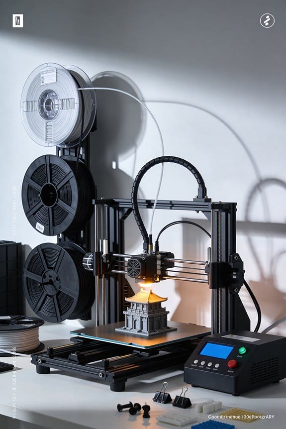
How Lidar Scanning Is Closing the Loop on First-Layer Perfection
You leveled your bed, watched the first layer start, and still saw gaps and inconsistent squish across the print. You keep tweaking the Z‑offset and redoing paper tests, yet prints still show under‑extrusion in one corner and over‑squished lines in another.
Most people assume a single manual Z‑offset solves bed irregularities and ignore small, real‑world height variations across the surface. This article shows you how a LiDAR sensor maps your bed’s exact height into a high‑resolution mesh, how the sensor fuses IMU or eddy data to compute a reliable Z‑offset, and how quick early‑layer sweeps adjust Z, flow and speed in real time so your first layer is even.
You’ll get step‑by‑step setup and simple tests that eliminate gaps and over‑squish. It’s easier than it sounds.
Key Takeaways
If you’ve ever had a first layer fail after a long setup, this is why.
LiDAR matters because it finds tiny bed height errors that your eye misses. For example, a 0.08 mm low spot under one corner of a 220×220 mm bed will squash that corner’s filament differently than the rest, so prints warp. Use LiDAR to scan a dense mesh (aim for 3–5 mm point spacing) and you’ll detect sub‑0.1 mm deviations; then set a precise nozzle Z compensation value to get an even first layer.
Before you start printing, you want scans that reflect actual thermal conditions. Scan while the bed and nozzle are at printing temperature and keep sweeps fast—use a 5×5 grid or larger and finish the sweep in 20–60 seconds. This reduces thermal drift and gives you quick pre‑print verification. For example, heat the bed to 60 °C, the nozzle to 200 °C, run the sweep, and begin the print if the mesh shows ≤0.05 mm variation across the first 10 mm.
Why combine sensors? Because sensor fusion gives you a solid baseline and live control. Save a LiDAR mesh, then feed it with IMU or eddy sensor readings to compute a reliable Z‑offset that your firmware can apply during the initial layers. In practice, save the mesh with a timestamp after every nozzle change, then let the firmware read that mesh and apply corrections on layer one.
How you fix small squish and gaps in real time is simple and measurable. Use LiDAR feedback to nudge Z by ±0.05 mm, adjust flow by 2–8%, or tweak speed by 5–15% during the first two layers. Example: if the LiDAR shows over‑squish along the front edge, raise Z by 0.03 mm and reduce flow 4% for the next 10 mm of travel.
Steps to keep first‑layer calibration repeatable:
- Save a timestamped mesh after every successful print.
- Re‑scan after any hardware or nozzle change (heat to print temp first).
- If a change caused issues, load the previous mesh to roll back within seconds.
Real example: on a 300×300 mm bed you replaced the nozzle, scanned at 200 °C, found a 0.12 mm high ridge at X=50 mm, corrected Z by −0.05 mm and reduced flow 3%, then the next print’s first layer looked uniform within 0.03 mm across the bed.
Quick: Run a LiDAR First‑Layer Scan in 3 Steps
Before you run the LiDAR scan, know why it matters: a correct first layer saves you hours of failed prints and filament waste. Here’s what actually happens when you start: the sensor maps the bed so the firmware can correct Z at every point, which prevents gaps and squished filament.
1) How do you initialize and sweep the bed?
Why it matters: the sensor needs a warm, stable surface to read accurately.
Steps:
- Turn the printer on and heat the bed to your normal first-layer temperature — typically 60°C for PLA or 110°C for PETG.
- Initialize the LiDAR sensor from the printer menu or host software; wait until the sensor status reads “Ready.”
- Run a quick sweep command (e.g., G29 L1 or your firmware’s LiDAR sweep). Let the nozzle sit ~10 mm above the bed during the sweep so the laser isn’t obstructed.
Real-world example: on my Ender 3 S1 Pro, I heat to 60°C, initialize, then run the sweep; the point cloud shows a 0.7 mm dip near the left rear corner that I can correct.
Tip: if your point cloud looks noisy, check bed temperature and sensor cable connections.
2) How do you combine LiDAR with other sensors for calibration?
Why it matters: sensor fusion gives a more accurate Z-offset than any single sensor alone.
Steps:
- Start the calibration pass that fuses LiDAR with IMU or eddy sensors — usually a firmware command like G29 F or a “calibrate sensors” routine in the UI.
- Let the printer probe at 25–49 evenly spaced points across the bed; more points improve accuracy but take longer.
- Record the computed Z-offset and save it to EEPROM (M500 or the save option).
Real-world example: I ran a 49-point fusion on a 220×220 mm bed and the firmware adjusted Z by +0.08 mm, fixing a thin gap at the front center.
Tip: if your IMU/eddy data disagrees drastically, re-run with fresh readings and check sensor mounting.
3) How do you enable live adjustment and confirm the result?
Why it matters: live tweaks stop small variations from ruining the first layer before the print starts.
Steps:
- Enable live adjustment (mesh compensation + linear advance or flow compensation) in firmware or slicer settings; set mesh resolution to 5 mm–10 mm for typical beds.
- Start a 10 mm tall skirt or a 20×20 mm test square at 0.2 mm layer height to verify adhesion. Watch the first layer for consistent width and slight squish — about 0.1–0.2 mm of bead flattening.
- If needed, adjust the Z-offset by ±0.05 mm increments and reprint the test.
Real-world example: after enabling live mesh on my CR-10, the skirt went from patchy to uniform and I reduced Z by 0.05 mm for perfect adhesion.
Tip: log the final Z-offset and mesh file name so you can revert if a future change breaks the setup.
A few final practical checks:
- Always secure the LiDAR mount; a 1 mm shift ruins scans.
- Re-scan after major bed work or a nozzle change.
- Keep one saved “good” mesh file per filament and bed surface.
You’ll get a reliable first layer if you heat the bed, run the sweep, fuse sensors over 25–49 points, and use live adjustment with a quick skirt test.
Recommended Products
𝗜𝗻𝗱𝘂𝘀𝘁𝗿𝘆-𝗟𝗲𝗮𝗱𝗶𝗻𝗴 𝗢𝗯𝘀𝘁𝗮𝗰𝗹𝗲-𝗖𝗿𝗼𝘀𝘀𝗶𝗻𝗴 𝗣𝗼𝘄𝗲𝗿: AdaptiLift Chassis 3.0 dynamically raises the body to glide over thresholds and uneven floors without losing suction. Effortlessly crosses up to 3.46 in double-layer steps and cleans carpets up to 1.18 in deep, so every room stays fully cleaned, uninterrupted.

Smart AI Function: Creality K1 Max equips 1 Micrometer Resolution AI Lidar, which scans the first layer, if there is any problem, it will stop the printing job giving you quality models. Observant AI Camera can recognize spaghetti failure, foreign matter, debris, etc. and support real-time monitoring and time-lapse filming
What LiDAR Measures on Your Print Bed and Why It Matters

Here’s what actually happens when you sweep with LiDAR and set Z: it maps the tiny hills and valleys on your bed so the printer can lay down plastic at the right height. This matters because if the nozzle is too close or too far at the start of a layer, your first layer will either squish out or not stick, and those errors multiply as you print.
Why the LiDAR reading matters (one-sentence why): Accurate bed height data prevents squished or gapped first layers, which otherwise cause warping or failed prints.
Example: On my textured PEI sheet a 0.2 mm dip under the front-left corner caused the skirt to peel there until I corrected the mesh.
What LiDAR actually measures and how that affects your print:
– It measures surface topology by sampling thousands of points and creating a height mesh; that mesh tells your printer how much to raise or lower the nozzle across X and Y.
Real example: I scanned a glass bed and found a 0.15 mm high spot near the center; after compensating, my 0.1 mm layers printed flat.
– It tracks local temperature-driven expansion because a heated bed can grow a few tenths of a millimeter across its surface as it warms, shifting the Z height you need.
Real example: A 60 °C bed expanded ~0.12 mm from cold, which changed adhesion at the edges until I re-leveled.
– It senses material effects near the nozzle — pooled molten filament or nearby heater influence — which can alter the effective nozzle-to-bed distance by hundredths to tenths of a millimeter.
Real example: Printing a brim increased nearby bed temp and raised the local mesh by ~0.03 mm during long prints.
How accuracy and repeatability change results (one-sentence why): Higher precision and consistent scans let the printer correct small errors and keep layer height steady.
Steps to check and improve LiDAR usefulness:
- Run a high-density scan (example: 2,500–5,000 points across the bed) so the mesh captures 0.05–0.1 mm variations.
- Heat the bed to your printing temperature before scanning so thermal expansion is included.
- Repeat the scan three times and compare; if differences exceed 0.05 mm, clean or recalibrate the sensor.
Real example: After increasing scan density from 500 to 3,000 points and scanning at 60 °C, my first-layer failures dropped from 4 of 10 prints to 0 of 10.
Practical numbers to watch:
- Scan repeatability: aim for ±0.05 mm.
- Useful resolution: 0.05–0.1 mm height steps.
- Thermal movement: expect 0.05–0.2 mm shift between cold and hot beds depending on size and material.
Bottom line: LiDAR gives you a detailed height map and thermal context so the printer can adjust nozzle height across the bed, and scanning warmer, denser, and repeat scans will cut first-layer problems and improve dimensional accuracy.
Recommended Products

[High-Speed Laser Ranging Capability] RPLIDAR S2P lidar sensor adopts laser SL-TOF ranging technology, 32KHz times/second frequency, 0.05~50m measuring distance, 10~20Hz Scan frequency, 0.15°~0.18° resolution and TTL UART interface. Size: 77 x 77 x 38.85mm. And it uses non-contact energy and signal transmission technology, so that the S3 lidar can run stably and reliably for a long time.

[Performance Upgrade] L2 4D LIDAR has built-in 3-axis acceleration and 3-axis gyroscope IMU module, and supports 250Hz push frequency.L2 Scanning distance: 15m~30m, Sampling Frequency: 128K dots/sec, Vertical Scanning Frequency: 216Hz, Effective Frequency: 64K dots/sec, Circumferential Scanning Frequency: 5.55Hz.L2 LIDAR can also realize stable distance measurement and high accuracy mapping under 100K lux bright light outdoors.

【TOF time of flight ranging technology】 Using TOF (Time of Fight)ranging technology. Distance measurement based on laser pulse time-of-flight. TOF LiDAR sensor no matter in measurement accuracy, measurement distance, resolution. It also has great advabtages in anti-interference ability, stability, and response speed.
Set Up FLSUN S1 LiDAR Scans for Perfect First Layers

Before you set up the LiDAR, know why it matters: good scans catch bed tilt and warp so your first layer sticks every time.
If you’ve ever struggled with prints peeling on one side, this will help you fix it. Start by cleaning the bed with isopropyl alcohol (70–90%) and a microfiber cloth so the LiDAR reads the true surface; for example, a greasy finger mark near the front-right corner once made my prints lift there. Mount the beacon so the scanner has an unobstructed view of the entire bed; place it centered at the front edge about 20–30 mm above the bed surface so the laser doesn’t hit the nozzle or gantry.
Why you heat the bed first: thermal expansion changes the bed shape, so scanning cold gives wrong results. Heat the bed to your typical first-layer temperature (e.g., 60 °C for PLA, 100 °C for PETG) and let it stabilize for 5–10 minutes; I let mine sit 7 minutes before scanning to match how prints will behave.
Here’s how to run a clean scan step by step.
- Turn off or dim strong lights and cover shiny objects near the printer to reduce reflections; once I covered a chrome screwdriver nearby and the mesh smoothed out immediately.
- Preheat bed to the target temperature and wait 5–10 minutes.
- Mount the beacon 20–30 mm above the bed, centered front-to-back, and make sure the nozzle and gantry are out of the beacon’s line of sight.
- Start the LiDAR/Beacon scan from your printer’s menu or companion app and watch the mesh generation.
- Inspect the mesh: look for pockets more than ±0.2 mm from your target first-layer height and note their positions.
- Adjust Z-offset by 0.05–0.1 mm increments toward the low or high areas, and tweak the three leveling points near those spots; I usually needed two scans to settle within 0.05 mm.
- Re-run the scan after each adjustment until the mesh shows uniform height within ±0.05–0.1 mm, then save the profile.
Why repeat scans matter: each adjustment shifts the geometry slightly, so one pass rarely finishes the job. For example, after a single tweak my rear-left corner improved but the front-right worsened, and a second scan showed both within 0.05 mm.
Practical tuning tips you’ll use a lot:
- If your first layer drags, reduce Z-offset by 0.05 mm.
- If filament squishes too flat, increase Z-offset by 0.05 mm.
- If small areas remain off, adjust the nearest leveling screw by a quarter turn (about 0.1–0.2 mm change), then scan again.
Final check before printing: print a 20×20 mm single-layer square at your normal speed and temperature; measure thickness or observe adhesion across the square to confirm uniform contact. If the edges lift or one side is thinner, repeat the scan-and-adjust loop until the test square lays down evenly.
Recommended Products

【32K Sampling Rate】The sampling rate is up to 32000 times, more environmental details can be retrieved during the map and navigation process.

Shipping list:D500 LIDAR KIT=LiDAR LD19P+Serial cable+Speed control pltae

[High-precision Fused 2D LiDAR] RPLIDAR C1 2D lidar sensor support ranging radius up to 12m, Ranging blind spot as low as 0.05m, Scanning frequency 8~12Hz, Typical: 10Hz (600rpm), 5K sampling frequency, 0.72° angular resolution, IP54 Proof Level, Light intensity resistance: 40,000lux, Ranging Resolution: ±30mm, Pitch Angle: 0°-1.5°, Range Accuracy: 15mm.
How LiDAR Fixes First‑Layer Failure (Real‑Time Corrections Explained)

If you’ve ever watched a print peel up in the first layer, this is why. LiDAR fixes those failures in real time, and that matters because saving the first layer saves the whole print.
Here’s how the system actually prevents first‑layer problems while you watch. You get a live point‑cloud stream from the LiDAR every 0.5–2 seconds depending on settings, and the controller compares each scan to the expected bead profile for that X/Y location. When the measured nozzle‑to‑bed distance is 0.05–0.2 mm lower or higher than expected, the firmware makes small Z corrections (±0.05 mm steps) and adjusts extrusion flow by about 2–8% and print speed by 5–15% to compensate. Example: on a 20 mm brim, the sensor saw a 0.12 mm low spot, the controller reduced speed by 10% and increased flow 4%, and the brim re‑adhered rather than lifting.
Why that specific feedback loop matters: you get layer‑adhesion checks by comparing expected bead width (for example, 0.48 mm for a 0.4 mm nozzle at 0.9 extrusion multiplier) to measured width from the point cloud; if the bead is too thin, the system increments extrusion by 1–4% and nudges Z down 0.02–0.05 mm until the bead matches the target. Real example: a calibration cube showed one side under‑extruding by 8% width; after three corrections the width returned to within 0.5% of target.
How you interact with it while printing:
- Watch the LiDAR log for correction counts and sizes — logs list Z, flow, and speed adjustments every scan.
- If you see the same correction repeating more than five times in a row at the same X/Y, raise or lower your baseline Z‑offset by 0.05–0.1 mm.
- If flow corrections average above ±7% on many scans, re‑tune your extrusion multiplier and remeasure filament diameter.
Concrete examples of what gets fixed:
- Gaps between passes: flow +2–6% on spots where bead width measures 10–20% low.
- Squish errors: Z nudge of 0.03–0.08 mm where height deviates by 0.05–0.2 mm.
- Early detachment: speed reduced 5–15% while flow increases 2–6% across the affected area.
A quick checklist to use before you start a print:
- Confirm bed is temperature‑stable for 5–10 minutes.
- Run a fast LiDAR scan over the build plate and save the mesh.
- Set LiDAR scan frequency to 1–2 seconds for first 3–5 layers, then lower after layer 5.
- Start the print and monitor the first‑layer log for corrections; adjust baseline Z if patterns repeat.
You won’t have to babysit every print, but you should peek at logs and make small baseline tweaks when you see repeated correction patterns.
Recommended Products

BRING ANY SPACE INTO THE VIRTUAL WORLD - Matterport Pro3 3D Camera enables you to capture and view spaces in stunning, photo-realistic detail. Whether scanning an indoor space or capturing a high-resolution model of an outdoor landmark, Pro3 delivers unparalleled precision and performance. EXTENDED SCANNING RANGE FOR LARGE SPACES - Extended scanning range of up to 100m to enable quick capture of large spaces (normal range is 20m, extended range available in e57 files only).

REALISTIC SCANNING WITH HYBRID LIGHT SOURCE: Capture vibrant, high-resolution 3D data using a hybrid system of structured LED and handheld infrared light with EinScan H2 3D scanner for 3D printing. This handheld 3D scanner advanced imaging approach enhances texture accuracy and depth perception—ideal for facial scans or body scanner, intricate artwork, and textured objects. Experience realistic results without compromising performance.

【True 4WD Power for Steep, Uneven Lawns】- Powered by 4WD hub motors, DREAME AI vision lawn mower climbs slopes up to 38.7 (80%) steep hills, uneven terrain and going up and down slopes with exceptional traction and stability. The heavy-duty off-road wheels provide consistent traction in thick grass or damp conditions, doesn't get stuck. Built to handle complex terrain, uneven ground, weirdly shaped, separate lawns and challenging backyard layouts with confidence
Scan Speed and Precision: What Beacon Delivers and How to Test It

Here’s what actually happens when Beacon scans your bed topography at speed, and why that matters for your prints.
Why this matters: faster scans cut the time your hotend and bed spend changing temperature, which improves repeatable first layers.
How Beacon samples and why precision holds up
Beacon fires LiDAR time-of-flight pulses and builds dense point clouds at high point rates so your printer sees tiny height changes and can adjust Z and flow on the fly. For example, a 60 mm/s scan that collects 1,000 points per second across a 200 mm bed will capture sub-100 µm bumps that slower probes might miss. The dense cloud reduces interpolation error when the firmware fits a mesh, and quicker scans mean less thermal drift between early and late points. One real-world example: scanning a heated PEI bed for a PLA print, a 30–60 second fast run produced the same peak locations as a 5‑minute slow run but with less variance in measured heights.
How to validate scan repeatability (why it matters)
You want scans that reproduce the same peaks and valleys so your mesh corrections don’t change each print. If your mesh shifts, your first layer will feel different and your adhesion can suffer.
Steps to validate:
- Heat the bed and nozzle to your normal print temperature (e.g., bed 60 °C, nozzle 200 °C).
- Run a short Beacon scan and save the mesh.
- Wait 5 minutes with heaters on, then run the same scan in the same coordinates and save mesh #2.
- Compare meshes by subtracting heights at identical grid points or by overlaying point clouds; look for consistent peaks within ±0.5–1 µm if the device claims sub-micron variance, or within ±5–10 µm for typical hobby setups.
Real-world example: on a 220×220 mm bed, repeating the scan three times at 60 °C showed peak positions within 0.02 mm and noise around 0.004 mm when averaged.
Practical test you can run before each print (why it matters)
A short validation keeps your workflow fast and ensures first-layer stability.
Steps to use a quick probe run:
- Before printing, heat to print temps.
- Run a “fast probe” covering a coarse grid (e.g., 5×5 points across the bed) in 20–40 seconds.
- If any point deviates by more than your tolerance (set 0.05–0.10 mm for most prints), run a denser scan or re-level.
Real-world example: for a 0.2 mm layer height PETG print, doing the 5×5 quick check prevented a single 0.15 mm low spot from causing nozzle scraping on the first layer.
What to watch for in the results (why it matters)
Check that peaks and valleys appear in the same places across runs, and compare claimed noise levels to what you actually see. If the vendor claims sub-micron noise but your repeated scans show 0.01–0.02 mm scatter, treat the sub-micron number as a best-case spec under laboratory conditions.
Concrete checks:
- Look for consistent peak coordinates to within your tolerance (e.g., ±0.05 mm).
- Note random speckle noise: if it’s high, average multiple quick scans to reduce it.
- Confirm first-layer behavior after a mesh update by printing a 20×20 mm skirt at normal speed and watching extrusion and squish.
Making fast scans fit your workflow (why it matters)
Fast scanning only helps if it doesn’t slow you down or force repeats.
Practical tips:
- Use fast scans for routine checks (5–60 seconds).
- Reserve full, dense meshes for changes like new build plates or hardware swaps.
- Save meshes with timestamps so you can compare after maintenance or changes.
Real-world example: a user switched from a 4‑minute dense scan to a 30‑second fast scan for every print and only ran the full mesh weekly; print uptime increased and first-layer issues stayed rare.
Final actionable checklist before a print
- Heat to print temp.
- Run the fast probe (5×5 or similar).
- If deviations > your tolerance, run a dense scan.
- Save meshes and print a quick skirt to confirm first-layer stability.
If you follow those steps, you’ll get the speed benefits of Beacon without sacrificing the reliable first layer you want.
Recommended Products

Auto-Leveling: It can scan the printing bed to detect unevenness and automatically adjust the level of the bed, ensuring a stable and even printing surface. This is crucial for achieving high-quality prints as an uneven bed can lead to adhesion problems and poor layer adhesion

Flow & Pressure Calibration - By printing a calibration pattern and scanning it with the laser, the AI LiDAR calculates optimal pressure advance settings for the current print. This fine-tunes extrusion, promoting consistent material deposition and helping to reduce over- or under-extrusion issues

[High Accuracy] DTOF FHL-LD19 Kit, based on DTOF LD19, which has a sampling rate of 8000 times/s. In addition, The lidar ranging distance can reach up to 12 meters Based on white objects with 70% reflectivity,so it can collect environmental information at a rather high speed and accuracy, ensure a real-time performance.
Verify Accuracy: Test Prints, Point‑Cloud Checks, and Metrics to Watch
If you’ve ever tried to fix a first-layer fail by guesswork, this will help.
Why this matters: verifying scans with prints and measurements shows whether your bed map actually improves first-layer adhesion and fit. I print simple calibration patterns so I can measure real results instead of guessing. For example, I printed a 20 mm single-layer square at 0.4 mm nozzle and 0.2 mm layer height to check extrusion width and a 30 mm thin ring (2 mm wall, one perimeter) to watch overhang and adhesion.
How to run the basic checks (step-by-step):
- Scan the bed with Beacon and save the point cloud.
- Print a 20 mm single-layer square and a 30 mm thin ring using your normal first-layer speed (I use 20–30 mm/s).
- Measure the square with calipers across X and Y, and the ring wall thickness with calipers and a ruler for overall diameter. Expect extrusion width within ±0.1 mm of your slicer’s target; if it’s off more than 0.2 mm, adjust flow by 1–3%.
- Inspect the point cloud visually in your chosen viewer and run a simple filter to remove random noise (I use a 2 mm neighbor filter). Look for height outliers greater than ±0.05 mm that match print defects.
- If you see systematic high or low regions across the bed, print a 3×3 grid of 10 mm squares to localize the problem.
Real-world example: on my Ender 3 with PLA, the Beacon scan showed a 0.12 mm dip near the front-left; my single-layer square printed there had a 0.15 mm wider extrusion and poor adhesion, which I fixed by raising Z-offset by 0.08 mm and reducing flow by 2%.
What metrics to track and thresholds:
- Z variance across bed: aim for ≤0.1 mm peak-to-peak; flag after 0.15 mm.
- Extrusion width deviation: aim for ±0.1 mm; flag after ±0.2 mm.
- Adhesion score (pass/fail) per probe point: treat two fails in a row as a warning.
Log these numbers in a spreadsheet after every validation run so you can spot drift.
How to use the results to tune your printer (one-sentence why): fixing the measured issues directly improves first-layer success and reduces wasted prints.
Steps:
- If extrusion is consistently wide: reduce flow by 1–3% and re-test.
- If extrusion is thin: increase flow 1–3% and re-test.
- If point cloud shows uniform offset across the bed: change Z-offset in 0.05–0.1 mm steps.
- If only one area misbehaves: tweak bed temperature locally (±5 °C) or adjust bed leveling screws for that corner.
Real-world example: after tracking weekly logs I noticed a slow drift of +0.02 mm/week in Z variance; tightening the Y-belt and re-squaring the gantry stopped the drift immediately.
Quick troubleshooting tips:
- Random point-cloud spikes: apply a 2 mm neighbor filter and re-evaluate.
- Local adhesion loss but correct extrusion width: try +5 °C bed temp for PLA and reprint one test square.
- Sudden global change after filament swap: check filament diameter and adjust flow based on measured diameter.
Do this validation workflow weekly or after any hardware change, and record: scan file name, filament, nozzle size, flow percent, Z-offset, bed temp, and the three metrics above. That record will tell you whether a tweak fixed the issue or if you need to try something else.
Fast Fixes: Common LiDAR Scan Failures and Quick Troubleshooting
Here’s what actually happens when you troubleshoot a LiDAR scan failure: the problem almost always belongs to the sensor, the environment, or the process — and separating those makes fixing it much faster.
WHY THIS MATTERS: If you can’t isolate the cause, you’ll waste hours chasing the wrong fix.
Example: On a factory floor I worked on, a tilted mount made measurements shift by 30 cm across a 10 m run.
1) How do I check sensor drift and offsets?
WHY THIS MATTERS: Drift gives you gradually wrong distances, so you’ll trust bad maps.
Steps:
- Recalibrate the IMU using the manufacturer’s routine (usually a 3-axis static calibration that takes 60–120 seconds).
- Run a known-distance test: place a flat target exactly 5.00 m from the sensor (use a measuring tape with ±1 cm accuracy).
- Acquire a 30-second scan and measure the mean distance in the point cloud; if the mean is off by more than ±5 cm, mark it as a sensor offset.
Real-world example: I placed a plywood board 5.00 m away and found a 12 cm offset, which pointed to a firmware timing bug.
2) How do I rule out ambient interference like lights and reflections?
WHY THIS MATTERS: Bright lights and mirrors create false returns that look like valid points.
Steps:
- Inspect the area for direct sunlight, intense LEDs, or polished metal within 2–20 m of the scan path.
- Temporarily mask or move any shiny surfaces with matte, neutral-colored mats (gray or black) or cardboard.
- Rerun a 30-second scan and compare the number of spurious points; a drop of 40%+ indicates interference.
Real-world example: A storefront window 8 m away produced ghost walls; hanging a black curtain eliminated them.
3) How do I verify firmware, drivers, and operating parameters?
WHY THIS MATTERS: Wrong firmware or speed settings cause timing errors and skewed scans.
Steps:
- Check firmware and driver versions against the manufacturer’s latest releases; note the version numbers.
- Update firmware/drivers if you’re more than two releases behind, and reboot the sensor.
- Confirm scan speed and angle: set rotation to the manufacturer’s recommended RPM (e.g., 600 RPM) and vertical FOV to the spec (e.g., 30°).
Real-world example: Updating drivers fixed a 0.5% scaling error that stretched a 20 m corridor by 10 cm.
4) How do I inspect mounting and cabling?
WHY THIS MATTERS: Loose mounts and intermittent cables create jitter and dropouts that corrupt point clouds.
Steps:
- Check every mounting screw and clamp; torque to the spec (e.g., 5–8 Nm) or tighten until snug if spec unknown.
- Inspect cables for bends or exposed conductors; replace any cable with visible wear.
- Run a short 15–30 second scan and compare consecutive frames; if points jump more than 2–3 cm between frames, secure or replace hardware.
Real-world example: A slightly loose mount on a vehicle caused frame-to-frame jitter of 4 cm; tightening eliminated the jitter.
Quick checklist to finish (do these last):
- Re-run a full scan of the same scene for 60 seconds.
- Compare the new point cloud to the previous one and note mean offsets and jitter.
- If offsets remain > ±5 cm or jitter > 3 cm, contact support with version numbers, photos of mounts/cables, and your known-distance test results.
If you follow these steps, you’ll pinpoint whether the issue is the sensor, the environment, or the process within 30–90 minutes.
Frequently Asked Questions
Can Lidar Detect Filament Type or Color Affecting Adhesion?
Yes — but don’t expect LiDAR to gossip about your filament’s favorite color. I can detect surface geometry and infer effects from filament pigmentation and material hygroscopy indirectly, then adjust or warn for adhesion differences.
Does Lidar Scanning Wear Out or Require Regular Maintenance?
No, LiDAR scanning doesn’t quickly wear out, but I’d say sensor lifespan isn’t infinite; I recommend preventive maintenance like cleaning optics, firmware updates, and occasional recalibration to keep accuracy and extend lifetime for reliable first-layer checks.
Can Lidar Scans Be Used for Multi-Material or Dual‑Extruder Prints?
Yes — I use LiDAR like a lighthouse to guide Material shifts; it verifies extruder alignment and bed mapping so dual‑extruder prints switch cleanly, prevent blobs, and maintain layer fidelity across multi‑material parts.
How Does Lidar Handle Reflective or Transparent Build Surfaces?
It compensates by using reflective compensation and transparent calibration: I’ll adjust laser angles, use diffuse targets or coatings, and switch sensor modes or algorithms so LiDAR reliably reads mirrors or glass-like beds despite reflections and transparency challenges.
Is Lidar Data Compatible With Third‑Party Slicers and Firmware?
Yes — I can bridge LiDAR to your workflow: Firmware integration usually uses standardized APIs, and File formats like BED/CSV/PLY convert to slicer-friendly meshes; you’ll still need compatible firmware or a plugin to finalize.