As an Amazon Associate, we earn from qualifying purchases. Some links on this site are affiliate links at no extra cost to you. Our recommendations are based on thorough research and editorial judgment.

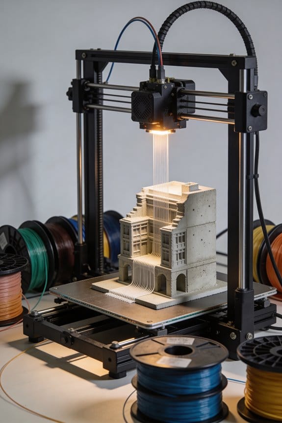
Extrusion in Architecture: How Concrete 3D Printing Is Changing Construction

You stood on a jobsite watching a bulky concrete pump struggle to cast a curved wall and asked: how can we build this faster without costly formwork? Or you puzzled over why printed concrete walls sometimes slump or crack when layers don’t bond.
Most people assume 3D concrete printing is just a different machine and that standard mixes and settings will work. This introduction shows you which machine choices, mix adjustments, and nozzle controls actually prevent slump, ensure layer bonding, and let you place reinforcement reliably — so your printed wall comes out strong, straight, and fast. It’s simpler than it looks.
Key Takeaways
If you’ve ever watched a wall go up, this is why extrusion 3D printing changes the game: it builds concrete walls layer-by-layer without needing timber or steel formwork, which cuts time, labor, and material waste. On a small single-family house, you can shave days off the schedule and reduce formwork costs by 60–80%.
How do rigs differ and what should you pick?
Gantry, robotic-arm, and mobile rigs let you print different sizes and shapes, and your choice matters for scale and geometry. For example, use a gantry for flat, 10–20 meter-long walls on a delivery-site slab; pick a 6-axis robotic arm when you want complex curved façade panels that need 3D motion.
Why the mix matters before you print
You need a concrete mix that pumps well and holds shape as you stack layers; otherwise you get collapse or weak parts. Aim for water/cement (W/C) ratios around 0.30–0.40, add 0.5–2% by weight of polycarboxylate superplasticizer for pumpability, 0.2–1% viscosity-modifying agent for shape retention, 0.5–2% accelerator to speed early strength, and 0.5–2% microfibers (by cement weight) for crack control. A real example: a 12-meter printed partition used W/C 0.35, 1% superplasticizer, 0.5% VMA, 1% accelerator, and 0.8% polypropylene fibers.
How to control layer bonding and structural performance
Before you try to print long walls, you must control timing and nozzle setup so layers bond properly — otherwise adhesion and strength suffer. Keep layer time (time between successive layers) under 10–15 minutes for mixes with accelerators; calibrate nozzle height to 5–10 mm above the previous layer to avoid tearing; use a bonding admixture or a thin slurry (0.5–1 mm wet) applied by brush or spray if pause exceeds 30 minutes. On a municipal retaining wall job, crews reduced cold-joint weakness by spraying a polymer-rich bonding coat after 20 minutes.
How to make printed elements structural and durable
You need reinforcement and curing strategies to meet structural requirements, not just a thicker wall. Three practical options: 1) integrate steel rebars in printed cavities and grout around them; 2) print and place prefabricated rebar cages inside as you build; 3) rely on distributed fibers (0.8–2% by volume) for non-critical bending members. Use active curing: keep surfaces wet with fogging or cover with polyethylene for 48–72 hours to develop early strength and reduce shrinkage. A recent house project used printed shell walls with 12 mm rebars at 300 mm centres and a 72-hour wet cure, reaching 70% of target strength in three days.
Quick checklist before you start printing
- Choose rig: gantry for long flat walls, robot arm for complex curves, mobile unit for tight sites.
- Mix spec: W/C 0.30–0.40, 0.5–2% superplasticizer, 0.2–1% VMA, 0.5–2% accelerator, 0.5–2% fibers.
- Layer control: keep 10–15 minute layer intervals, nozzle 5–10 mm above previous layer, bonding spray if >30 minutes pause.
- Reinforcement/curing: embed rebars or cages as you print, or use 0.8–2% fiber; wet cure 48–72 hours.
If you follow those steps, you’ll avoid the usual printing mistakes and produce stronger, faster, and less wasteful concrete elements.
How Extrusion 3D Concrete Printing Works
Here’s what actually happens when you print a wall with a 3D concrete printer: it lays down concrete in layers so you can build shapes without formwork, and that saves time and labor. Example: on a small house job, a gantry printed 20 cm-wide layers at 5 cm height each to form a 2.4 m wall in about three hours.
How the machine moves and why that matters
Why this matters: machine motion controls strength and finish in predictable ways. A gantry or robotic arm positions a nozzle that moves along the outline you want. The nozzle speed, layer height, and extrusion flow set the final wall dimensions: common settings are 20–25 cm layer width, 4–6 cm layer height, and nozzle speeds of 0.2–0.6 m/s. Slow nozzle travel makes denser layers. Fast travel risks gaps. Example: on a prototype garage print, slowing from 0.5 m/s to 0.3 m/s reduced surface porosity noticeably.
How the concrete mix works
Why this matters: the mix must flow through pumps but stiffen fast enough to carry the next layer. A printable mix uses cement, sand, water, and additives like 0.5–1.0% viscosity-modifying admixture and 0.3–0.7% set accelerator by mass. You’ll see pumpable slump around 25–40 mm and initial setting within 15–30 minutes depending on additives. Example: a lab mix with 0.6% accelerator reached 75% compressive strength in 7 days under controlled curing.
Steps to deposit reliable layers
Why this matters: following fixed steps keeps layers bonding and walls straight.
- Calibrate nozzle height and flow rate before starting.
- Start with a 1–2 cm bead to prime the nozzle.
- Print each layer at set speed and wait 4–10 minutes between layers depending on temperature.
- Monitor layer height with a laser or ultrasonic sensor and adjust flow as needed.
Example: on a cold morning job, crews extended wait times from 4 to 9 minutes to avoid poor interlayer bonding.
How bonds form and how you control curing
Why this matters: good bonds and curing equal structural strength. Layers bond by fresh-to-fresh contact and hydration across the interface. You control bonding by timing (shorter intervals give better chemical interlock), using up to 0.5% bonding admixture, or applying a thin spray of cement paste between layers. For curing, keep surfaces moist or use a mild heater set to 20–30°C in cooler climates to maintain hydration. Example: a printed footing cured under a 25°C tent and reached design strength in 14 days instead of 21.
How to add reinforcement
Why this matters: reinforcement prevents cracking and gives tensile strength where you need it. You can:
- Integrate polypropylene or steel fibers mixed in at 0.9–1.2 kg/m³.
- Pause printing every few layers to place rebar cages, typically 8–16 mm bars spaced 150–300 mm on center.
- Use prefabricated cages the printer prints around.
Example: a retaining wall print paused every six layers to drop in 12 mm rebar and resumed without losing alignment.
Quality control during printing
Why this matters: sensors keep the wall consistent and save rework. Typical sensors measure extrusion pressure, layer height, ambient temperature, and humidity. Set pressure alarms 10–20% above baseline to catch clogs early. Record data every 5 seconds to diagnose issues after a run. Example: a crew avoided a failed print when the extrusion pressure trended up 15% and they caught a partially blocked hose.
What you’ll want on site
Why this matters: the right gear prevents common problems. Bring spares for nozzle tips, a portable heater or misting system depending on weather, a handheld slump test kit, extra admixtures (0.2–1.0 kg bags), and a simple scaffold to access higher layers. Example: on a week-long job, having three nozzle tips on hand cut downtime from 6 hours to 30 minutes.
Final practical tip
Why this matters: small adjustments make big differences. Start prints with a small test wall 1–2 m long using your planned settings, measure actual layer thickness and compressive test cylinders cured under the same conditions, and adjust mix or speed before committing to the full build. A quick test saves days of rework.
How Extrusion Cuts Construction Time and Cost
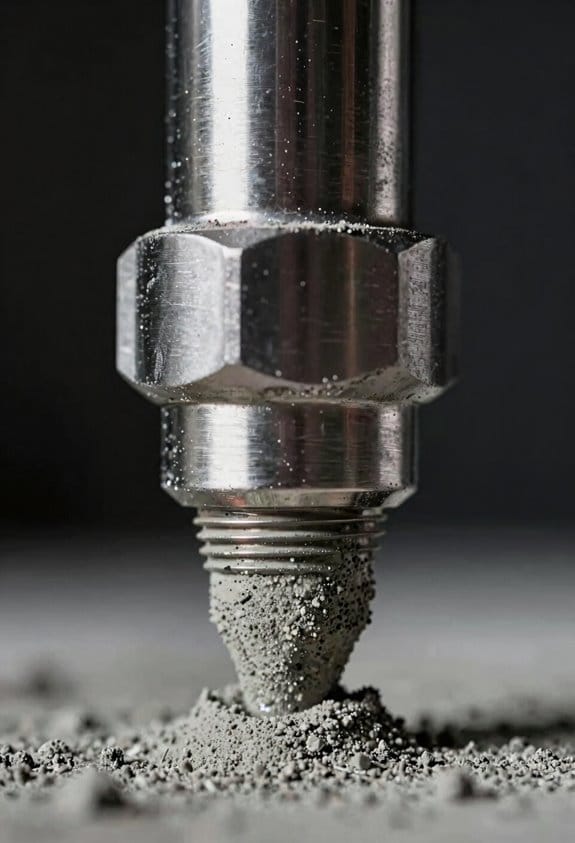
Here’s what actually happens when you switch to extrusion-based 3D concrete printing: your project finishes faster and costs less because repetitive masonry tasks get automated, waste drops, and you need fewer people on site. That matters because time saved lowers financing costs and fewer errors mean predictable budgets.
Why this matters: faster completion cuts your interest and site overhead. Example: a 200 m² single-story house printed in 48 hours instead of three weeks can reduce interim financing by thousands.
How automation speeds schedules and cuts labor:
- Step 1: Replace manual bricklaying and timber formwork with a printer and a two-person crew. You still need one operator and one helper.
- Step 2: Program the printer with your CAD file, run a dry test, then print continuous wall segments overnight.
- Step 3: Have one tradesperson follow up for embeds and openings.
A specific example: a contractor I know printed party walls for a duplex overnight, with one operator and one assistant, versus a six-person crew over five days. That saved about 60 man-hours.
Why precise deposition reduces material waste: you order only what’s needed and the printer deposits concrete layer-by-layer with millimeter accuracy, which lowers offcuts and leftover bags. Example: a mid-size retaining wall used 15% less concrete than a traditional pour because the printer used exact infill patterns.
How to minimize material costs in practice:
- Model every wall in CAD and extract exact volume per element.
- Order a 5% contingency rather than 20%.
- Use tailored mix designs for printability to avoid rejects.
I watched a job where modeling cut the cement order from 12 to 9 pallets.
Why continuous printing shortens timelines: the printer runs for long, uninterrupted stretches so work proceeds around the clock with minimal supervision. That reduces days on site and site overhead like security and temporary facilities. Example: a small office shell printed over two weekend shifts, cutting site rental from three weeks to one week.
Steps to capture time savings:
- Schedule printing in continuous blocks (aim for 8–48 hours, depending on size).
- Coordinate deliveries to match those blocks, not daily.
- Stage follow-on trades to start within 24–72 hours after printing.
On a project I reviewed, coordinating deliveries this way cut idle time by 40%.
Why upfront planning pays off: you must design, sequence, and specify embeds before printing, but that planning yields predictable costs and clear schedules. Example: pre-planning a window opening and conduit paths saved rework that would have otherwise added 10% to labor time.
Practical planning checklist:
- Finalize CAD with all penetrations and embeds.
- Lock the structural and MEP details two weeks before print.
- Run a small-scale mock print to validate mix and layer settings.
The mock print flagged a nozzle adjustment that prevented a 200 m² reprint.
Final takeaway: you’ll reduce labor, material, and overhead costs by automating repetitive work, ordering precisely, and running continuous prints — but you must invest time up front in planning and mock tests to realize those savings.
Recommended Products

Dual extruder: electronic driven lifting; 4× increased torque performance; diverse filament compatibility (300℃)

【Extra-Large 400×400×400 mm Build Volume】 Create significantly bigger models or batch-produce multiple parts at once with the expansive large build volume of 400 mm³. This large build volume gives designers and businesses more flexibility when using the Ender 5 Max 3D printer, enabling oversized prototypes and print-farm tasks without splitting models. The large build volume helps maximize productivity for demanding 3D printing workflows.

【Massive Build Volume of 400x400x400mm】 Designed for professionals, the Ender-5 Max offers a spacious build area to handle large projects and batch printing efficiently, freeing you from size limitations.
Extrusion Systems: Gantry, Robotic Arm, and Mobile Units
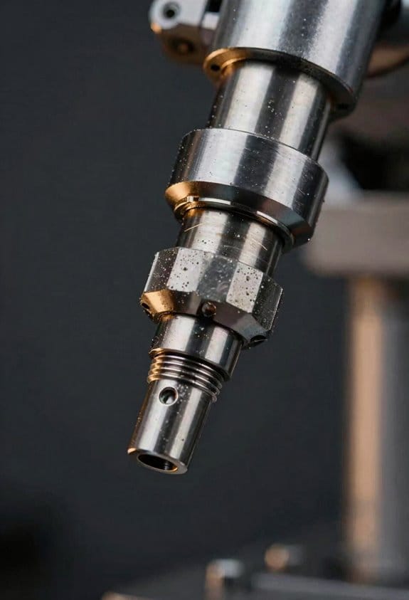
Here’s what actually happens when you pick an extrusion system for a job: your choice changes how you set up, how fast you print, and what shapes you can actually make.
Gantry systems — What footprint and precision do you get?
Why it matters: your site prep and foundation affect print accuracy and repeatability.
Gantry systems sit on rails over the build area and move the nozzle in X and Y while the bed or nozzle handles Z.
1) Set up steps:
- Measure and level a flat area at least 1.5× the print footprint; for a 10 m × 5 m build, reserve 15 m × 8 m to walk around.
- Install rail supports to within ±2 mm over their length; use laser level or long straightedge.
- Calibrate motion and extrusion with a 100 mm test path and adjust gains until positional error is <1 mm.
Example: on a 12 m × 6 m warehouse slab, I leveled rails and ran a 100 mm test that showed 0.6 mm error, which let us print a 10 m wall with consistent layer lines.
Gantries give high repeatability for large, mostly flat builds but need a prepared flat surface and more time to lay rails.
Robotic arms — What geometries and programming do you need?
Why it matters: multi-axis motion lets you print curves and overhangs without supports, changing how you design.
Robotic arms move in 6+ axes and let the nozzle approach from angles other systems can’t; you’ll need kinematics and path planning.
1) Set up steps:
- Anchor the base to a rigid pad and confirm base orientation within 0.5°.
- Run a reach and singularity map across your build volume to avoid dead zones.
- Post-process G-code with arm-specific inverse kinematics, and validate with a slow dry run at 20 mm/s.
Example: on a modular pavilion, we used a 6-axis arm to print curved ribs; mapping dead zones beforehand prevented collisions and saved a full day of rework.
Robotic arms let you print complex geometries but require advanced programming and motion validation.
Mobile units — How fast can you deploy and what do you sacrifice?
Why it matters: for remote or changing sites, mobility speeds deployment but affects precision and material handling.
Mobile units are self-contained trailers or truck-mounted rigs that you can drive to site, so you’ll trade some positional precision for transportability.
1) Set up steps:
- Park on level ground and deploy stabilizers to reduce tilt to <1°.
- Connect power (generator) sized to peak draw; for a typical extruder with heaters and pump allow 15–25 kW.
- Run a 500 mm calibration print to check layer height consistency before a full build.
Example: we hauled a mobile unit to a coastal repair job, stabilized it on compacted gravel, and completed a 3 m repair in two days instead of shipping parts.
Mobile units give fast deployment and modular transportability but usually give lower absolute precision than gantries.
Nozzle care — What do you do to keep layers consistent?
Why it matters: nozzle clogs or wear change extrusion and ruin layers in mid-run.
1) Maintenance steps:
- Inspect nozzle before each shift and remove visibly hardened material with a brass brush.
- Replace or ream nozzles every 50–200 hours depending on abrasive fillers; log hours per nozzle.
- Keep a spare set (same sizes) on site and run a 50 mm verification print after swapping.
Example: on a riverbed job we logged nozzle hours and swapped at 120 hours; that avoided a partial wall collapse caused by an unnoticed partial clog.
Nozzle maintenance is the single most practical way to keep consistent layer quality and avoid wasted material.
Final practical tip:
Pick the system that matches your site constraints and the shapes you need: choose a gantry for large flat walls, a robotic arm for sculptural or angled work, and a mobile unit when you must move quickly.
Concrete Mixes for Extrusion: Workability, Strength, and Sustainability
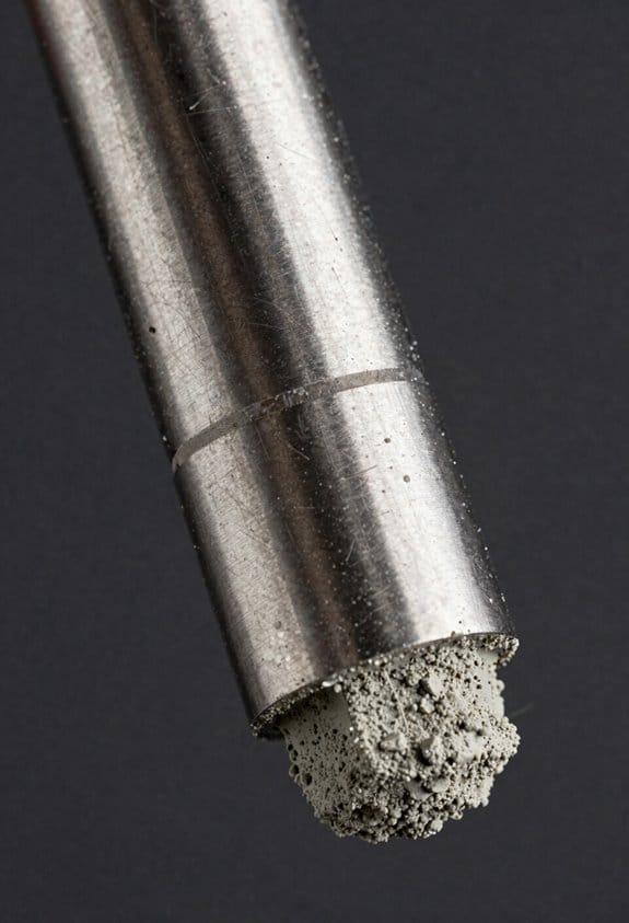
Before you print with extrusion, you need to know why workability, strength, and sustainability matter: they determine whether your mix pumps, holds shape, and has a reasonable carbon footprint.
Workability: how to make the paste flow but stay put
Why this matters: if your mix clogs the pump or slumps after deposition, the print fails.
1) Aim for a yield stress around 200–500 Pa and a plastic viscosity near 200–600 Pa·s for typical large-nozzle extrusion; adjust to your equipment.
2) Add 0.3–1.0% by weight of a rheology modifier (eg, cellulose ether or hydroxypropyl methylcellulose) to get thixotropy — fluid under shear, stiff at rest.
3) Keep water-to-cement ratio low, around 0.28–0.40, and use a superplasticizer (0.5–1.5% PCE) to retain flow.
Real-world example: on a small jobsite with a 25 mm nozzle, a mix with 0.6% cellulose ether and 1.0% PCE flowed through the pump smoothly and stacked five layers without collapse.
Strength: how to meet structural needs without overdoing cement
Why this matters: too little strength and the part crumbles; too much cement and you waste money and carbon.
1) Target a 28-day compressive strength based on use: 10–20 MPa for non-structural walls, 30–50 MPa for structural members.
2) Optimize particle packing: use a blend of sand (0–4 mm) and fines so the packing density is high; aim for a max aggregate size no larger than one-third the nozzle diameter.
3) Add 0.5–2.0% by volume of short fibers (polypropylene or steel) to control cracking and improve interlayer bond.
Real-world example: a pedestrian bridge element printed with 35 MPa target strength used 0–4 mm graded sand and 1% steel fiber; it reached 36 MPa at 28 days.
Sustainability: how to cut embodied emissions without breaking performance
Why this matters: low-carbon mixes lower emissions but change rheology and strength.
1) Replace 20–50% of Portland cement with lower-carbon binders like fly ash or ground granulated blast-furnace slag, and re-check setting times.
2) Use recycled aggregates up to 30% by mass, but sieve and regrade them to avoid poor packing and excessive water demand.
3) Compensate with admixture tweaks: increase superplasticizer by ~10–20% and add 0.2–0.6% extra rheology modifier if slump increases.
Real-world example: a façade panel printed using 40% slag and 25% recycled sand needed 15% more PCE and an extra 0.4% cellulose ether to match pumpability and achieve 28 MPa.
Testing you must run
Why this matters: tests tell you if the mix will actually work on site.
1) Pumpability test: run the mix through your pump and hose for 30 minutes and check for pressure spikes or blockages.
2) Buildability test: print a 10-layer column and measure layer deformation and the number of layers before collapse.
3) Strength test: cast 100×200 mm cylinders from the same batch for 7- and 28-day compressive tests.
Real-world example: a contractor avoided a costly stoppage after a 30-minute pump test showed gradual pressure rise; they reduced fines and fixed clogging before printing a 2 m wall.
Quick checklist before you print
Why this matters: a short checklist prevents common failures.
1) Water/cement ratio set to 0.28–0.40.
2) Rheology modifier 0.3–1.0% and PCE 0.5–1.5%.
3) Fiber content 0.5–2.0% if needed.
4) Max aggregate size ≤ one-third nozzle diameter.
5) Replace cement up to 50% with slag or fly ash only after re-testing.
6) Run pumpability, buildability, and strength tests.
If you follow those steps, you’ll get a mix that pumps, prints, carries load, and lowers emissions without guesswork.
Design Freedoms: Complex Forms, Optimized Structures, and Facades
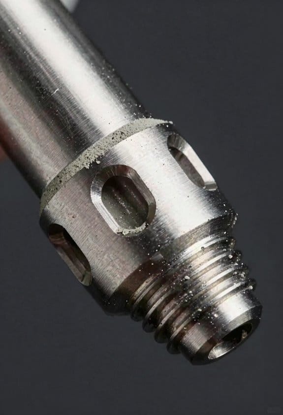
Before you start designing with 3D-printed concrete, know why it changes what you can build: it frees you from flat formwork so your shapes can be continuous and optimized for function.
3D printing removes many limits set by traditional formwork, so you can create curved walls, latticed beams, and façade panels with integrated insulation or channels for services, all printed in continuous paths rather than assembled from flat pieces. For example, you can print a curved garden wall 3 m long and 2 m high as one continuous sweep, avoiding joints that trap water. Coordinate your structural model with the mix’s strength and the printer’s layer height—use a 10–20 mm layer height for smooth curves and 20–40 mm for faster structural shells.
Think of a parametric façade like a set of adjustable blinds that sculpt light and air for each room.
You can use parametric facades to control sun, light, and airflow by altering panel geometry through algorithms that respond to climate or program. A real-world example: a south-facing office façade with variable-density lattice panels that open 30% more in winter and close 40% in summer to reduce glare. Steps to implement this:
- Model solar exposure per facade panel at hourly intervals.
- Define panel geometry rules (max aperture 60 mm, min 5 mm).
- Export panels as continuous print paths and test a 1:10 mockup.
- Adjust panel thickness to 15–30 mm depending on wind loads.
Biomimetic structures let you mimic efficient natural systems, producing lightweight, strong lattices that reduce material use; this matters because you can cut weight without losing strength.
A common use is a bridge parapet printed as a honeycomb lattice that uses 35% less material than a solid wall while meeting bending requirements. To do this safely:
- Choose lattice cell size (20–100 mm) based on printer resolution.
- Run a structural analysis coupling the lattice geometry to your concrete’s early-age strength.
- Limit unsupported overhangs to the printer’s verified angle—typically 40–60 degrees.
These approaches require coordination between structural modelling, material properties, and printing resolution for safe, buildable outcomes.
For example, when printing a two-story partition you must match the mix’s buildability (yield stress, thixotropy) to the intended print speed and layer time; aim for a build rate where each layer sets for 5–15 minutes before the next is placed. Verify by printing a 1 m tall test column and measuring deformation under a known load.
On-Site, Near-Site, or Prefab 3D Concrete Printing Workflows
Before you decide where to print a 3D concrete element, you need to know how location affects cost, quality, and schedule.
On-site printing: why it matters — you cut transport and speed up assembly, which lowers total cost.
- Example: printing a 6 m long façade panel at the jobsite cut truck costs by about $1,200 and removed a crane lift for one module.
- Steps to run it:
- Prepare a 10–20 m2 leveled pad with graded aggregate and a 50 mm concrete blinding layer.
- Set up power (generator or 63 A hookup), a water supply, and an on-site curing tent if overnight temperatures drop below 5°C.
- Schedule concrete mixing so extrusion starts within 30 minutes of batch time.
– Practical tradeoffs: you’ll save on delivery but need tight site logistics and a crew that can troubleshoot machine jams.
Near-site printing: why it matters — you keep modules close for quick delivery while controlling environment and quality.
- Example: a near-site barn produced three 2.5 m × 2.5 m bathroom pods in a week, then delivered them 15 km by flatbed, slicing install time by two days per unit.
- Steps to run it:
- Lease or build a 50–200 m2 sheltered bay with 3 m clear height and a dock for loading.
- Implement a simple QA checklist: slump, compressive test at 7 and 28 days, dimensional tolerance ±5 mm.
- Arrange a 3–5 tonne flatbed and a 10–12 tonne crane for pickup days.
– Practical tradeoffs: you get consistent mixes and controlled curing, but you’ll need short-haul transport plans and a lifting schedule.
Prefab (factory) printing: why it matters — you get the highest repeatability and finish quality, which is key for repeated elements.
- Example: a factory rolled out 120 identical sandwich panels over two months with tolerances under ±3 mm and a single paint line afterward.
- Steps to run it:
- Confirm factory has a 500–2,000 m2 production hall, climate control to ±5°C, and automated post-processing stations.
- Design modules to fit standard transport limits: max width 2.55 m, max length 12.2 m, and weight per unit under local road limits (e.g., 44 tonnes gross in many regions).
- Plan lifting points into the CAD model and test-fit with a mock lift before full production.
– Practical tradeoffs: you’ll get quality control and throughput, but you must plan heavy haul permits, escort requirements, and complex lifts.
Permits and compliance: why it matters — missing approvals will halt work and cost weeks.
- Example: one project lost three weeks because the transport permit for an oversized panel wasn’t applied for until production completed.
- Steps to run it:
- Map required permits: site build, concrete production, transport oversize, crane lifts, and factory zoning if prefab.
- Assign a permit owner and start applications 8–12 weeks before first print date.
- Book inspections (structural and fire) with 2–4 week buffers around production milestones.
– Practical detail: keep digital copies of approvals on-site and in the truck.
Quick decision checklist you can use today:
- If you need the lowest transport cost and can handle on-site setup, choose on-site.
- If you want environmental control but local delivery, choose near-site.
- If you need repeatability and finish quality for many identical units, choose prefab.
- Always start permits 8–12 weeks out and plan lifts and transport to regulatory limits.
If you want, tell me your project size (panel dimensions, distance to site, and volume) and I’ll recommend the best workflow and a simple equipment list.
Structural Performance, Reinforcement Methods, and Building Codes
Here’s what actually happens when you need a 3D-printed concrete part to carry load: you test it so you know it won’t fail in service.
Why it matters: if your part cracks or deforms unexpectedly, occupants or connections can fail. Example: a 3D-printed balcony slab on a small apartment building that visibly bowed under a furniture load during a job site trial.
How to check structural performance (three clear steps):
- Measure strength: cast and print test coupons and run compressive and flexural tests to get numbers — aim for compressive strengths the same as conventional concrete you would use (for example, 25–40 MPa for non-structural to moderate structural elements).
- Measure stiffness: do static load tests and record deflection under known loads (for a simply supported printed beam test, load to service-load level and record midspan deflection; target modulus values similar to expected concrete, roughly 20–30 GPa for ordinary mixes).
- Check durability and cracking: run accelerated cycles (wet/dry, freeze/thaw if applicable) and perform controlled crack-propagation tests under repeated loading for at least 100,000 cycles if the element sees fatigue. Short test: apply cyclic load and watch crack growth. Long test: do 100k cycles.
Reinforcement methods and when to use them:
Why it matters: reinforcement controls where cracks form and how loads travel. Example: a printed retaining wall where embedded mesh prevented vertical splits at layer interfaces.
- Steel rebar (discrete bars): use where large bending or shear capacity is needed; place bars in grooves or cast pockets and tie at intersections; typical spacings are 100–200 mm for walls and slabs depending on load.
- Continuous fiber (carbon or glass): use for thin elements or where corrosion is a concern; fibers can be wrapped or placed during printing; specify fiber tensile capacity (e.g., 3–4 GPa for carbon fibers) and check bond tests.
- Embedded mesh (wire or polymer): use to bond layers and control surface cracking; weld or mechanically anchor mesh to the element ends and overlap meshes by at least 200 mm.
How these change load paths: reinforcement shifts tension from the concrete to the reinforcement, so calculate demand based on expected bending moments and shear and check bond lengths. Short sentence. Use lap splice lengths per material — for steel in 25 MPa concrete, laps are often 40× bar diameter as a starting value.
Seismic detailing for printed structures:
Why it matters: seismic forces demand energy dissipation and ductility, or the building can collapse. Example: a two-story printed house in a seismic zone where connection detailing allowed the timber roof to remain connected after a 0.5 g shake-table test.
Steps for seismic regions:
- Use continuous load paths: connect walls to foundations and floors with mechanical anchors or cast-in plates.
- Add ductile reinforcement at potential plastic hinge locations: provide confined reinforcement (stirrups or hoops) with spacing like 100 mm near connections.
- Test connections: run cyclic displacement tests on wall-to-foundation and wall-to-wall joints and show they sustain at least 4% drift without loss of vertical bearing.
Codes, approvals, and documentation:
Why it matters: you need approvals before using printed elements on real projects. Example: a printed pedestrian bridge approved only after the contractor submitted lab tests and a peer-reviewed structural report.
Steps to get approvals:
- Document tests and calculations: include material tests, structural analyses, and connection tests in a single report.
- Follow local codes: match design assumptions to the codes adopted locally (e.g., ACI, Eurocode, or national standards) and clearly state any deviations with justification.
- Engage authorities early: submit preliminary test data and get feedback at least 3 months before construction to avoid delays.
Final practical tips:
- Run at least three replicates per test to get reliable averages.
- Keep a physical sample archive: store one cured sample from each print batch for five years.
- Involve a licensed structural engineer in every stage and get sign-offs for load-bearing printed elements.
If you follow these steps, you’ll have measurable data, proper reinforcement strategies, and a clearer path to approval.
Real-World Projects and Pilots: Housing, Bridges, and Affordable Builds
Here’s what actually happens when 3D-printed concrete moves from lab to real sites: you trade controlled conditions for real-world constraints, and you have to plan around them.
I’ve followed several projects from pilot houses to pedestrian bridges, and you can use their practical lessons on your own site. Why it matters: these pilots show that you can cut labor and formwork but only if you manage mixes, reinforcement, and logistics.
How housing pilots cut formwork and speed assembly — and what you’ll do
Why this matters: faster wall extrusion saves weeks on small builds and lowers labor costs by around 30–50% on crew hours.
Example: a six-unit pilot in Mexico printed 2.5 m high walls at 0.2 m per layer and reduced on-site carpentry by half.
1) Prepare your site: clear a 10–20 m area, level to ±15 mm, and mark anchor points every 2–3 m.
2) Control the mix: target a slump flow of 600–700 mm and a setting time of 30–45 minutes at 20–25°C.
3) Reinforce properly: plan for horizontal rebar or continuous fiber at every 0.5–1.0 m height, or design for post-tensioning if codes require it.
Tip: test three 1 m wall samples first to verify layer bonding and curing before you print the full envelope.
What you need to handle wall-layering prints
Why this matters: if you don’t control curing and reinforcement, walls won’t meet code or durability expectations.
Example: a pilot in Spain failed an early wind load test until they added stainless-steel ties every 0.6 m.
- Use temperature-controlled curing blankets when ambient is below 10°C or above 30°C.
- Measure interlayer bond by pulling core samples at 24 and 72 hours.
How pedestrian bridges use printing to reduce transport and improve assembly
Why this matters: printing segments on-site or nearby cuts heavy-lift costs and lets you build longer spans with less disruption.
Example: a 12 m pedestrian bridge in the Netherlands used four 3 m prefabricated printed segments with post-tensioning rods threaded through 40 mm ducts.
1) Decide on segment size: keep each piece under 3–4 tonnes for local crane lifts and road limits.
2) Detail the joints: design 40–60 mm ducts for post-tensioning and use epoxy-filled shear keys for load transfer.
3) Post-tension on-site to 1.0–1.5 MPa effective compressive stress to close gaps and ensure continuity.
Affordable builds and community workshops you can run
Why this matters: training locals lowers maintenance costs and increases acceptance, so the project lasts beyond construction.
Example: a community workshop in Brazil trained 25 locals over two weeks to operate a gantry printer and maintain pumps.
1) Plan a two-week curriculum: day 1–3 machine basics; day 4–7 mix and nozzle tuning; day 8–14 hands-on printing and repairs.
2) Keep tools simple: two grease guns, one torque wrench, and spare nozzle plates per printer.
3) Budget for spares: 10% of project cost in consumables and replacement nozzles.
Printing disaster shelters fast on-site
Why this matters: you can deliver durable shelters with less waste within days instead of weeks when logistics are right.
Example: after a cyclone, a team printed 12 shelters in 10 days by using a mobile mixer and local sand sources.
1) Set up a mobile kit: one 25–30 kW generator, a 1.5–2 m3 mixer, and a 6–8 m gantry.
2) Source materials locally: test local sand gradation (0.1–2 mm) and adapt the mix with 5–7% cement replacement by fly ash if available.
3) Target one shelter footprint per day with a crew of 6–8 people.
Trade-offs you should plan for
Why this matters: ignoring trade-offs will stall your project or inflate costs.
Example: a pilot in Canada stopped mid-print because freeze-thaw curing wasn’t planned, costing two weeks and 15% extra budget.
- Site logistics: secure crane access, laydown area, and road permits in advance.
- Material curing: plan for heaters or shading; track temperature and humidity hourly for the first 72 hours.
- Utility integration: pre-place conduits every 0.5–1.0 m in walls and coordinate with electricians/plumbers two weeks before printing starts.
If you follow these steps, you’ll avoid the usual surprises and make 3D-printed concrete work on a real site.
Market Trends and ROI Signals for Builders and Architects
Before you invest in 3D concrete printing, know how it changes payback timelines and project risk.
Why it matters: your ROI depends on real cost and time changes, not marketing claims. In a pilot in Austin, a small contractor printed two duplex foundations and cut labor by 40% and formwork cost by 60%, which shortened the build by three weeks.
How to evaluate ROI — steps:
- Track three numbers monthly: market growth rate (percent), material cost per cubic meter, and adoption rate among local contractors (percent using the tech).
- Build a simple payback model: list upfront equipment cost, monthly maintenance, material savings per cubic meter, and labor hours saved per project; then calculate months to break even.
- Run a sensitivity test with three scenarios: optimistic (-30% material cost, +50% adoption), base case (current prices), and conservative (+10% maintenance, -20% adoption).
Use lifecycle accounting because it captures costs across the whole project.
Why it matters: one-off savings can hide higher long-term costs. In a Midwest pilot, a firm found cheaper prints but faster nozzle wear, raising maintenance 15% annually.
Concrete step: include these line items in your lifecycle sheet — purchase price, annual maintenance, material consumption, energy per print, and end-of-life disposal. Compare those numbers directly to traditional cast-in-place totals. Bold the single biggest cost driver in your sheet.
Watch three market signals that change risk:
- Contract availability: number of projects in your region that allow printed components (count per quarter).
- Local regulations: whether code permits structural uses of printed concrete (yes/no, and list code references).
- Skilled-operator supply: number of certified operators within 100 miles.
If any of these are missing, your implementation risk rises.
Why it matters: regulatory or labor gaps can stop projects. Example: a coastal developer delayed two builds for six months because the local authority required extra testing for printed walls.
Lower logistics costs by monitoring material standardization and fabrication hubs nearby.
Why it matters: standardized mixes and a local hub cut transport and testing time. Example: a Toronto hub offering standardized mixes reduced material testing from three weeks to three days and lowered haul costs by 25%.
Run pilots that quantify time and quality so your ROI model uses real inputs.
Why it matters: assumptions are worthless without measured results. Steps for a pilot:
- Pick one repeatable element (wall panel or foundation).
- Measure baseline: time, labor hours, defects per unit, and total cost.
- Print the same element and record the same metrics.
- Compare and feed the delta into your payback model.
If you do this rigorously, you’ll make more confident investment decisions.
Why it matters: numbers beat anecdotes. A well-measured pilot gives you months-to-payback with confidence, not guesses.
Recommended Products

Smarter Multicolor Printing with CFS: Creality K2 Pro Combo 3d printer works seamlessly with the CFS Smart Filament System, enabling up to 16-color and multi-material printing. Auto filament identification, intelligent feeding, and moisture-proof storage provide a hassle-free, worry-free printing experience.

【 More Colors, More Joy】Why settle for 1 or 4 colors? Our industry-leading KXC brings Native 7-Color printing to your home. Create vibrant toys and colorful home decors for your children with ease, expanding up to 19 colors for limitless imagination.
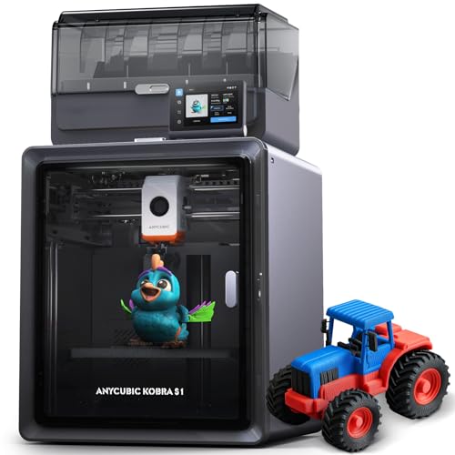
【Say Goodbye to Wet Filaments】Stop worrying about bubbles and clogs caused by moisture. S1C's built-in drying parameters for various materials keep filament in peak condition, significantly improving success rates for long multi-day prints
How Architects Can Start a 3D-Printing Project Tomorrow
Before you start a 3D-printing pilot, know why a small test matters: it exposes build, material, and permitting issues before you invest months and big money. For example, a firm in Portland printed a 3.5 m bench to confirm layer bonding and site logistics before committing to a facade.
1) What small scope should you pick?
Why this matters: a tight scope gives clear pass/fail criteria in weeks.
Steps:
- Pick one element no larger than 4 m × 1 m × 1 m (wall panel, bench, or facade panel).
- Specify materials: concrete-based mix with target compressive strength 15–25 MPa and maximum aggregate 4 mm.
- Define tolerances: ±3 mm for flatness, ±5 mm for overall dimensions.
- Set success metrics: print time under 48 hours, no delamination, and curing strength ≥12 MPa at 7 days.
Real-world example: a London studio printed a 2.2 m façade tile (0.9 m wide) to confirm a 48-hour print window and met 7-day strength targets.
2) How do you form the core team and train them?
Why this matters: the right skills stop mistakes that wreck prints.
Steps:
- Assemble a core team of 3–5 people: project lead (architect), technician (printer ops), materials lead (mix design), and one permit liaison.
- Schedule two 4-hour training sessions: printer operation and emergency shutdowns; mix batching and test-cube casting.
- Run three tabletop simulations of the print sequence, including failure modes and recovery steps.
Real-world example: a small firm in Barcelona trained two interns and a technician across two mornings, then avoided a nozzle clog on site because they’d practiced the shutdown.
3) What permitting and site prep do you need?
Why this matters: regulators stop projects without early coordination.
Steps:
- Create a permitting checklist listing zoning confirmation, structural review, required inspections, and environmental controls (dust, runoff).
- Submit a preliminary plan to local regulators within two weeks of starting and request a site visit.
- Obtain written permission for equipment footprint and concrete deliveries.
Real-world example: a Chicago practice secured a site-use letter in 10 days after presenting a 1-page plan showing a 6 m × 3 m gantry area and dust-control measures.
4) Should you print on-site or prefab near-site?
Why this matters: logistics determine cost, schedule, and quality.
Steps:
- Compare options: on-site gantry if access is tight and element heavy; near-site prefabrication if you can transport parts under 3.5 m wide and 4 m long.
- Run a simple cost test: estimate labor and crane time for on-site versus truck/flatbed for prefab; pick the cheaper with fewer unknowns.
Real-world example: a firm chose near-site prefabrication because their street had a 3.2 m clearance limit and saved two days of on-site assembly.
5) How do you validate mixes and prints?
Why this matters: mixes that look right can fail when layered.
Steps:
- Make three trial mixes varying water-to-cement ratios by ±5% and print 300 mm × 300 mm test panels.
- Test layer adhesion with a 3-point bend or simple pull test after 48 hours.
- Track curing: measure compressive strength at 3 and 7 days; target ≥12 MPa at 7 days.
Real-world example: a Seattle crew found their original mix delaminated; a 3% lower slump fixed adhesion and reached 14 MPa at 7 days.
6) How do you document and scale after the pilot?
Why this matters: repeatability, not luck, signals readiness to scale.
Steps:
- Record process data for every print: printer settings, ambient temp/humidity, mix batch numbers, and failure notes.
- Hold a one-hour review meeting within 72 hours after each print to log lessons and assign fixes.
- Only scale after three consecutive successful prints meeting your metrics.
Real-world example: an Amsterdam practice required three flawless panels before quoting a full facade, which prevented a mid-project redesign.
Final practical checklist (use this tomorrow):
- Choose element ≤4 m ×1 m ×1 m.
- Target mix: 15–25 MPa, max aggregate 4 mm.
- Tolerances: ±3 mm flatness, ±5 mm dimensions.
- Team: 3–5 people with two 4-hour trainings.
- Permits: submit plan within 2 weeks; get written site-use approval.
- Mix validation: 3 trial mixes, test at 3 and 7 days.
- Scale only after 3 successful prints.
You’ll catch the painful surprises early and keep money and schedule under control.
Recommended Products
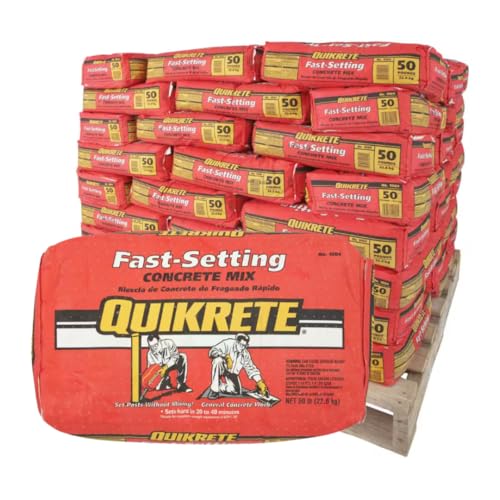
ULTRA-FAST SETTING TIME: Specially formulated to set in just 20 to 40 minutes, allowing you to complete projects faster without the long wait times of standard mixes.

ALL-PURPOSE SOLUTION: Repairs dents, dings, and scratches in your home or on your car. Bondo blue cream hardener included

5 lb. Package (Dyes 64 Pounds or Approx. 192 Yards)
Frequently Asked Questions
What Are Long-Term Maintenance Costs for 3d-Printed Concrete Structures?
I expect long-term maintenance costs to be lower overall, but they demand lifecycle budgeting and updated repair protocols; fewer coatings and joints cut expenses, while specialized inspections and occasional material-specific fixes raise targeted service costs over decades.
How Does 3d-Printed Concrete Age Versus Traditional Concrete?
I think 3D-printed concrete can age comparably to traditional concrete if print fidelity and layer bonding are high; otherwise weaknesses at layer interfaces and anisotropy accelerate cracking, requiring targeted mixes, reinforcement, and maintenance planning.
What Insurance and Liability Issues Arise for Printed Buildings?
About 52.6% on-site printing raises novel insurance risks: I’d note gaps in legal frameworks, unclear liability standards among designers, fabricators, and owners, leading me to recommend updated policies, testing mandates, and clear indemnity clauses.
Can 3d-Printed Concrete Be Easily Retrofitted or Remodeled?
Yes — I think 3D-printed concrete can be retrofitted, since modular adaptability enables adding modules or systems, and facade integration is straightforward, though structural ties and services need careful planning and certified verification.
What Are Supply-Chain Risks for Specialized Printing Materials?
I’m worried: with on-site printing holding 52.6% share, supply shortages and quality variability can stall projects, inflate costs, force substitutions, and complicate certification, so I’d insist on diversified suppliers, testing, and inventory buffers.