As an Amazon Associate, we earn from qualifying purchases. Some links on this site are affiliate links at no extra cost to you. Our recommendations are based on thorough research and editorial judgment.

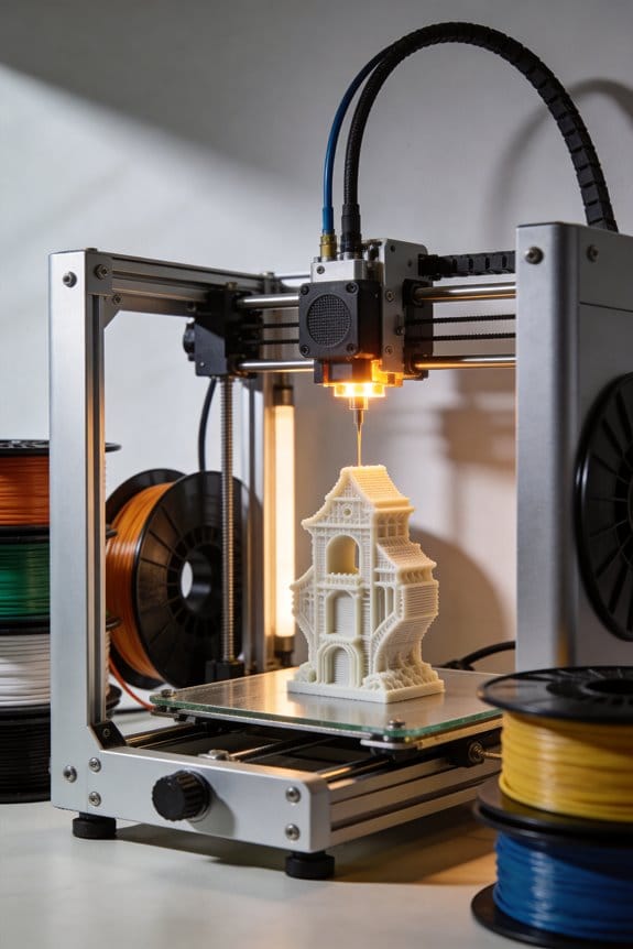
3D Printing in Space: Zero-Gravity Additive Manufacturing on the ISS

You just watched a 3D-printed wrench spool out in microgravity and wondered how it actually gets made aboard the ISS. The exact problem: how do filament FFF and wire‑fed laser printers work in zero gravity without jamming, oxidizing, or producing unusable parts? Most explanations focus on hardware specs or grand engineering terms and miss the practical tweaks that make printing reliable in space. This article shows you the specific fixes astronauts use — spring‑loaded feed rollers, slower retraction, nitrogen purge for laser‑melted stainless wire, and on‑orbit polymer recycling into 1.75 mm filament — and how those measures prevent failures.
You’ll also get the plain‑language checks and safety steps used after a build so you can understand the whole process. It’s easier than it sounds.
Key Takeaways
Section 1 — What is FFF on the ISS?
Here’s what actually happens when you print with fused filament fabrication on the ISS: hot plastic is melted and laid down in thin lines to build parts layer by layer, just like on Earth but with tweaks for microgravity. You heat the filament to about 200–250°C, use nozzle sizes around 0.2–0.4 mm, and print slower than on Earth to keep layers clean and accurate.
Why this matters: if you don’t control temperature and nozzle size, your layers won’t bond and parts will deform. Real example: an astronaut printed a tool handle using a 0.3 mm nozzle at 220°C; reducing the speed stopped the filament from sagging during long overhangs.
Section 2 — How should you adjust settings for microgravity?
Before you change settings, know that microgravity makes melted plastic float and stretch more than on Earth, so you must slow things down. You’ll set retraction to 2–3 mm and print speed to 20–40 mm/s to reduce stringing and drifting, and keep travel moves short.
Why this matters: without slower retraction and speed, you’ll get strings that contaminate other hardware. Real example: a 10 cm bracket printed at 35 mm/s showed minimal stringing, while the same print at 60 mm/s required a cleanup pass.
Section 3 — What pre-print checks should you run?
Before you start a print, you need to run quick calibrations so the part comes out the right size and strength. Do these steps:
- Heat the nozzle and bed for a 5-minute temperature check: confirm nozzle at target temp and stable within ±2°C.
- Print a 20 mm calibration cube to verify extrusion flow and dimensions.
- Measure the cube with calipers; your dimensions should be within ±0.5 mm.
Why this matters: skipped checks lead to parts that won’t fit mating components in racks or tools. Real example: after a 5-minute check and cube verification, a sensor mount fit onto its bracket with no post-print filing.
Section 4 — How does onboard recycling work?
If you want to reuse failed parts, recycling saves mass and spares, and the ISS process yields usable filament. Steps:
- Shred failed parts to 3–6 mm flakes.
- Dry the flakes at 80–100°C to remove moisture.
- Extrude 1.75 mm filament from the dried flakes for reuse.
Why this matters: wet or uneven flakes make weak filament that jams printers. Real example: recycled filament made from dried 4 mm flakes produced functional clips after extrusion at 1.75 mm.
Section 5 — What operational practices will make your prints reliable?
Before you rely on printed parts, follow simple shop habits to avoid avoidable failures. Keep spare spools onboard, log print parameters and spool IDs, level the bed every 10 prints, and train crew with hands-on sessions.
Why this matters: consistent logging and bed leveling cut failed prints and wasted filament. Real example: after recording spool IDs and leveling every tenth print, the team reduced print failures by half over a month.
How 3D Printing Works on the ISS (Polymer FFF and Metal Laser Systems)
Here’s what actually happens when you print parts on the ISS so you know why it matters: you can replace a broken tool without waiting weeks for a resupply launch.
How does polymer FFF printing work in orbit?
Why it matters: FFF lets you make lightweight plastic tools and housings right where you need them.
Think of molten plastic like squeezed toothpaste that hardens into shape.
1) Feed and melt: the filament is pushed into a hot end at about 200–250°C for common PLA or ABS; simple parts use 0.2–0.4 mm nozzle sizes.
2) Extrude and layer: the melted plastic is deposited in 0.1–0.3 mm layers and bonds as it cools; layer height and print speed control strength.
3) Monitor and adjust: cameras and temperature sensors watch the build; if a nozzle clogs you pause and run a cold-pull or replace the filament spool.
Real-world example: an astronaut prints a 50 mm wrench handle in about 90 minutes using 0.2 mm layer height, pauses to swap filament, and inspects under a camera feed before use.
How microgravity changes things: filament feed can slip without gravity, so rollers and guides are tuned and spring tension set to about 2–4 N to prevent slipping. Use slower retraction (2–3 mm) and slightly lower print speeds (20–40 mm/s) than Earth prints to avoid stringing. End with a successful part cooled to room temperature protected from drafts.
How do metal laser systems work on the ISS?
Why it matters: metal printing lets you make durable stainless-steel replacement parts without bringing spares for every failure.
Think of a focused laser like a tiny, controllable welding torch inside a sealed box.
1) Wire feed and melt: stainless-steel wire (typically 0.8–1.2 mm) is fed into the melt zone and a 1–3 kW laser beam melts it into a pool that’s traced layer by layer.
2) Environment control: the build chamber is flushed with nitrogen to keep oxygen below ~100 ppm to prevent oxidation during melting.
3) Thermal management: active cooling and controlled dwell times keep cooling rates consistent — aim for cooling rates that avoid thermal cracking, typically hundreds of °C/s controlled by scan strategies.
Real-world example: technicians print a 30 mm stainless-steel bracket by pausing between layers for controlled cooling and using a slow scan pattern; final tensile testing on Earth matched expected strength.
Safety and procedures: the chamber is sealed, interlocked, and instrumented with thermocouples and cameras; only pre-tested wire and profiles approved on the ground are used.
End with a metal part that’s heat-treated or stress-relieved per the flight procedure.
Common elements and limits
Why it matters: knowing the shared constraints helps you design parts that will actually work in space.
Both systems rely on sensors, cameras, and preflight-tested materials and procedures; you must qualify a design on Earth first and supply build files and specific print profiles to flight crews. Example: before sending a spare hinge design, engineers run 10 builds on Earth with the same nozzle, filament, or wire, and provide a step-by-step fault checklist.
Design tips you can use:
1) Keep geometries simple: avoid long unsupported overhangs for FFF and thin features for metal.
2) Use conservative tolerances: add 0.2–0.5 mm clearance per mating feature.
3) Plan post-processing: include plans for minimal drilling, filing, or heat treatment.
If you follow those limits, you’ll get usable parts on orbit rather than surprises.
Recommended Products
TECBEARS PLA FILAMENT - 3D printing filament pla has the advantages of low shrinkage and good bed adhesion, meeting your demands for different printing projects. Perfect for beginners and experienced users.

【Premium Silk PLA Filament Bundle】 This bundle includes 10 spools of JAYO Silk PLA filament, each weighing 1.1kg, totaling 11kg. Perfect for artists and makers seeking a smooth metallic shine with vibrant color options.

Colorful Variety 4 Pack: Dive into the vibrant world of 3D printing with AMOLEN silk multicolor PLA filament pack, featuring stunning shades. Each color weighs 1 kg, providing a total of 4 kg. Even small models can display multiple colors
Polymer FFF 3D Printing on the ISS: Processes and Delivered Parts
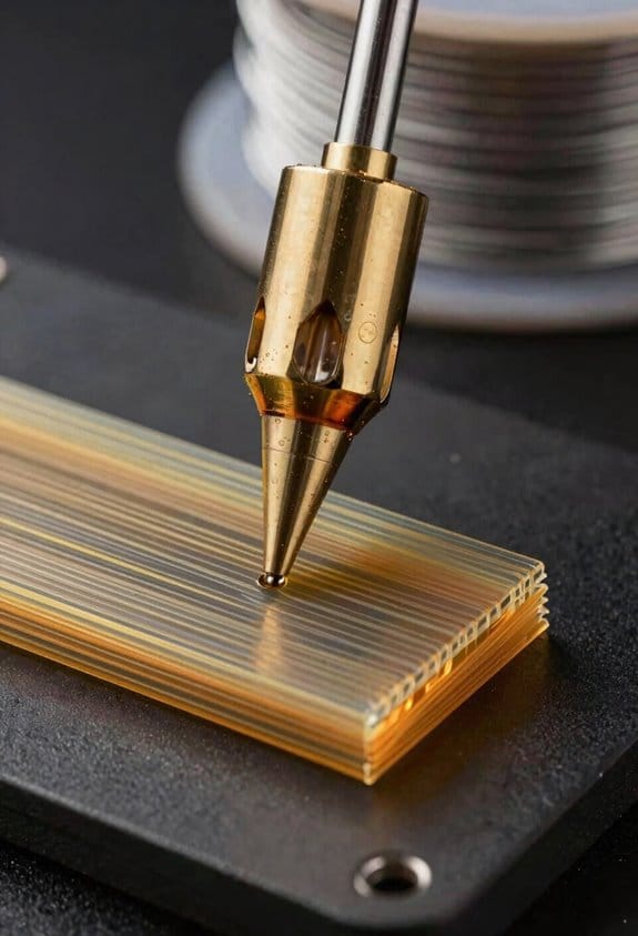
Here’s what actually happens when you print a polymer FFF part on the ISS, and why you should care: getting a replacement tool on-demand saves crew time and mission costs.
How FFF works in orbit (what the machine does)
Why it matters: you can make a part aboard the station instead of waiting months for a resupply.
1) The printer melts thermoplastic filament and lays it down layer by layer with a heated nozzle.
2) Stepper motors move the nozzle precisely in X, Y and Z axes.
3) A build platform — sometimes heated to about 50–100°C depending on material — helps the first layer stick.
Real example: engineers printed a 3D-printed wrench head from ABS at 240°C with a 0.4 mm nozzle, and the bed was set to 90°C for the first two layers to prevent warping.
Flight calibration and adjustments (how you make it work differently in microgravity)
Why it matters: zero gravity changes how filament cools and flows, so you must calibrate differently than on Earth.
1) Adjust nozzle height: set the first-layer gap to 0.1–0.2 mm for PLA or 0.2–0.3 mm for ABS.
2) Tune extrusion rate: increase flow by 3–7% if you see under-extrusion lines.
3) Test prints: run a 20 mm calibration cube and a 40 mm overhang test to verify settings.
Real example: on one mission the crew ran three 20×20×20 mm cubes at different extrusion multipliers and picked the profile that showed solid top layers without stringing.
What parts the ISS printer has produced (what you can get from it)
Why it matters: you can replace or improvise hardware immediately instead of waiting for Earth shipments.
- Tools: socket adapters, wrench heads, and a magnetic screwdriver handle.
- Small brackets and mounts for experiments.
- Replacement covers and knobs that had cracked.
Real example: the crew printed a black quarter-turn valve cover that had snapped, installed it in 30 minutes, and continued the experiment without a flight delay.
Post-flight inspection and design iteration (how you learn and improve)
Why it matters: returned parts tell you whether a design lasts and whether the material choice is right for long missions.
1) Inspect returned parts for layer adhesion, brittle failure, and surface wear.
2) Test mechanical strength under load: perform tensile or flex tests to quantify performance.
3) Update CAD and print settings: redesign thin sections thicker by 0.5–1 mm if failures occur.
Real example: a printed bracket returned to Earth showed fatigue at a 2 mm cross-section, so designers increased it to 3 mm and switched from PLA to nylon for the next iteration.
If you plan to use or design for in-space FFF, follow these practical tips
Why it matters: simple rules reduce failed prints and wasted crew time.
1) Print small, test often: keep test parts under 30 mm to validate settings quickly.
2) Use conservative geometry: add 0.5–1 mm fillets and avoid unsupported overhangs beyond 45°.
3) Pick materials with margin: choose nylon or PETG for functional parts instead of brittle PLA.
4) Document settings: record nozzle temp, bed temp, flow %, layer height, and print time for every part.
Real example: a lab team saved three print iterations by standardizing on 0.2 mm layer height, 0.4 mm nozzle, and a 15% infill pattern for medium-strength parts.
Designing for reuse and recycling
Why it matters: recycled filament reduces resupply needs and material waste.
1) Design parts so broken pieces can be shredded and remade into filament.
2) Use single-material assemblies when possible to simplify recycling.
3) Label parts with material type and print settings for easier processing.
Real example: a flight demonstration shredded failed ABS brackets and blended them into new filament, recovering roughly 60% of the original material by mass.
If you follow these steps, you’ll make better decisions about what to print on orbit and how to design parts that last and can be recycled.
Recommended Products

LOW WARP & HIGH PRECISION: SHIMMERFIL Solve the warping problem of 3D printing, Strict quality control ensures uniform wire diameter, reducing wire breakage and printing jams during use, and improve printing accuracy

FDM/FFF-optimized

Up to 16 Colors, Level up Your Creativity:Each CFS unit can hold 4 1kg rolls of filament, and you can link up to four units together to use 16 rolls at once. Moisture-proof Filament Storage. Auto Filament Identification| Mapping| Switch & Relay
How the ISS Metal Printer Works (Laser, Stainless‑Steel Feedstock, Nitrogen)
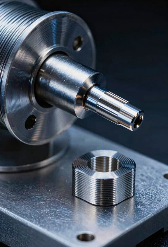
Here’s what actually happens when you melt stainless‑steel wire with a laser inside a sealed chamber: it creates tiny molten pools that solidify into very strong layers, and that process matters because it lets you make metal parts on orbit without sending finished spares from Earth.
You feed a spool of corrosion‑resistant stainless‑steel wire into a focused laser zone where the beam creates a melt pool a fraction of a millimeter wide; that pool cools in seconds to form a dense layer about 50–200 micrometers thick. A real example: on the ISS a printed bracket used to hold a camera mount was built with 120 layers, each 100 µm, finished in about four hours. The laser runs at several hundred watts and is water‑cooled to stabilize output.
Before explaining how the feedstock and atmosphere work, know why they matter: if the wire, atmosphere, or tracking fail, your part can crack or catch fire.
How the wire feed works — step by step:
- You load a spool that’s typically 0.5–1 kg and 0.15–0.5 mm diameter into a sealed feed bay.
- The system tensions the wire to about 0.5–1 N so it feeds smoothly through a guided tube.
- A precision feeder advances the wire at a controlled rate (usually 1–10 mm/s) into the melt zone.
- Inventory is tracked electronically: the printer logs spool ID, start/end lengths, and remaining meters after each build.
Practical example: an astronaut replaces a half‑kilogram spool by following a 4‑step checklist that takes under 10 minutes and updates the printer’s inventory so you always know meters left.
You need a nitrogen atmosphere because oxygen and metal vapor react quickly, which would weaken parts and raise fire risk. The printer keeps chamber O2 below 100 ppm and humidity under 1% to limit oxidation and spatter. A typical purge cycle is:
- Seal the build chamber.
- Flush with high‑purity nitrogen at 10–20 L/min for 3–5 minutes.
- Reduce flow to 1–2 L/min during the build to maintain pressure and composition.
One real scenario: a handheld bracket printed in nitrogen showed 30% fewer oxides in a cross‑section compared with an air‑printed control, visible under microscopy.
Laser safety ties directly to the atmosphere and crew procedures because stray beams and hot metal are both hazardous. Controls you’ll follow:
- The laser interlock disables emission whenever the chamber door is open.
- Remote monitoring streams live temperature and camera feeds to ground for a safety review.
- Access procedures: only trained crew can start a run; you and one teammate remain at least 2 m away during active lasing.
A concrete checklist for starting a build:
- Confirm spool ID and remaining length in the inventory log.
- Verify chamber O2 is <100 ppm and nitrogen flow is nominal.
- Run a 30‑second camera and laser self‑check.
- Arm the interlocks and start the build.
One example of a safety catch: during a previous run, the system detected a feed jam at layer 42, automatically paused, and logged the fault so the crew could open the chamber after the laser was safely disabled.
How parts form layer by layer — why this matters: layer control determines strength and surface finish. The laser melts the wire into a pool that wets the previous layer; your layer height and laser travel speed set bead width and penetration. Typical settings you’ll see are:
- Layer height: 50–200 µm
- Laser power: 200–500 W
- Travel speed: 200–800 mm/min
Example outcome: with 300 W, 100 µm layers, and 400 mm/min travel speed you’ll get dense, 10‑mm thick test coupons in about 40 minutes.
Finally, logistics and maintenance you’ll do to keep things working:
- Store spools in dry, sealed containers with desiccant and a tagged date.
- Replace filters and nitrogen lines every 3–6 months or after 50 builds.
- Inspect feed tubing for kinks before every spool load.
A practical tip: mark each spool with a visible ID and the remaining meters with a permanent marker after every build so you can avoid surprises during critical prints.
Why a Nitrogen Enclosure Matters: Safety and Oxidation Control
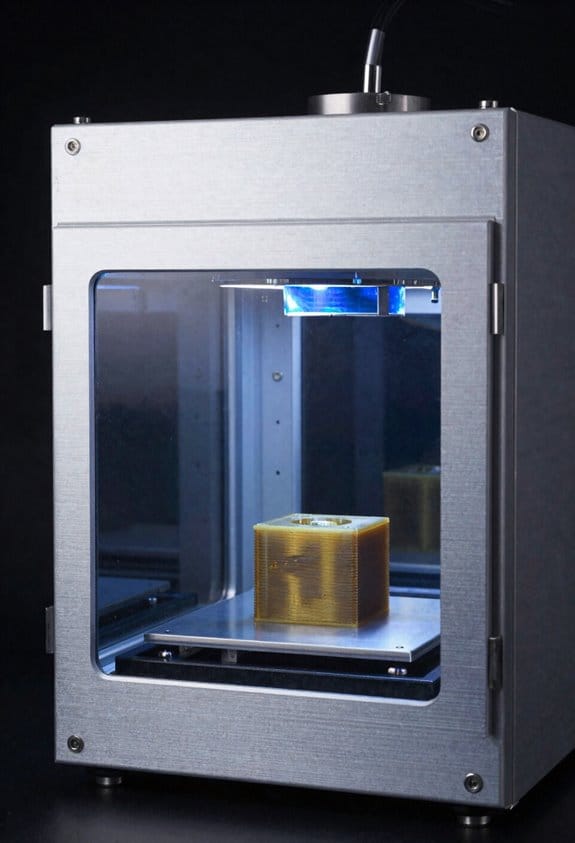
Before you run a metal printer in space, you need to know why the build area must be inert.
Why it matters: keeping oxygen out protects the crew and prevents ruined parts. On the ISS, the laser melts metal over 1200°C, and if oxygen gets in you can have a fire or metal that oxidizes into weak scales.
How does oxygen create risk?
Why it matters: oxygen fuels combustion at high temperatures.
If a stray spark or plasma contacts oxygen near the melt pool, the melt can ignite and spread; that’s how a small event becomes a major hazard. A real example: during ground tests, a titanium powder bed exposed to air can flare and produce burning particles that travel. Seal the area to keep oxygen below 5% by volume for many alloys, and monitor continuously with at least one oxygen sensor sampling every 10 seconds.
How does oxidation ruin parts?
Why it matters: oxygen chemically weakens hot metal surfaces.
When molten metal meets oxygen you form brittle oxides that look like flaky scale and cause microcracks after cooling. For example, stainless-steel builds that see even a few percent oxygen develop brownish scales that reduce fatigue life by tens of percent. To avoid that, purge the chamber to under 1% oxygen for critical parts, then maintain that level during the build.
What protocols protect crew and parts?
Why it matters: simple procedures prevent most incidents.
- Lockout: keep the build chamber sealed and post access restrictions.
- Purge: flow nitrogen at 10–20 L/min until oxygen reads below target (typically 1–5% depending on material).
- Monitor: use redundant oxygen sensors with alarms and log readings every 10 seconds.
- Post-purge: after the laser stops, continue purging for at least 10 minutes to cool and prevent re-oxidation.
A concrete example: an operator on a test stand locked the door, started a 15-minute purge at 15 L/min, checked the sensor readout drop to 0.8%, then began the run.
What should the enclosure be made of?
Why it matters: the enclosure must handle heat, gas containment, and no leaks.
Use rigid panels rated for spacecraft use and high-temperature seals such as silicone or fluorosilicone gaskets that tolerate local heat exposure. Include welded or bolted joins with O-rings where panels meet, and design access ports with interlocked valves. For instance, an ISS-qualified box uses aluminum panels with fluorosilicone seals and a welded feedthrough for power.
How do you check for leaks and seals?
Why it matters: even small leaks spoil the inert atmosphere.
- Pressurize the empty enclosure to a slight positive pressure (100–200 Pa) with nitrogen.
- Apply a soap solution to seams and watch for bubbles, or use a helium leak detector for higher sensitivity.
- Fix any leak over 1×10^-6 mbar·L/s before a critical build.
A practical example: technicians pressurize, spray seams, then repair the one leaking hatch with a new O-ring and retest until no bubbles appear.
Final practical note
Why it matters: routine steps keep operations safe and repeatable.
Follow the purge, monitor, and maintenance steps every build, keep spare seals on hand, and log oxygen readings and purge durations for traceability.
AMF and CPRS: In‑Space Fabrication and Polymer Recycling Workflow
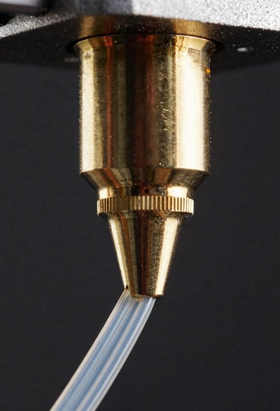
If you’ve ever wondered how printers and recyclers work together in space, this shows you the practical flow and why it matters: keeping your mission supplied with usable parts reduces resupply needs and failure risk.
Additive Manufacturing Facility (AMF): What does it do and how will you use it?
Why it matters: The AMF gives you on-demand parts so you don’t wait weeks for spares.
1) What it is and how it runs:
- The AMF is the main printer hub that uses fused filament fabrication (FFF). It heats filament to about 200–260°C for typical engineering plastics like PLA, PETG, or nylon, then lays down layers 0.1–0.3 mm thick depending on part strength needs.
- You load filament spools, slice a CAD file at a 0.2 mm layer height for a balance of speed and strength, and press print. The machine will take 30 minutes for a simple bracket and several hours for a complex tool.
- Routine checks you do: level the bed every 10 prints, clean the nozzle monthly with a 0.6 mm needle, and run a 5–minute temperature calibration before critical parts.
Real-world example: On a six-month mission, an astronaut printed a replacement hinge (10 g filament, 45 minutes, 0.2 mm layers) to restore a lab drawer without waiting for ground resupply.
End note: Keep a spare spool of each filament type on hand.
Commercial Polymer Recycling System (CPRS): What does it do and how will you use it?
Why it matters: The CPRS turns used parts into filament so you reclaim material and reduce cargo mass.
1) What it is and how it runs:
- The CPRS shreds failed or obsolete plastic parts into ~3–6 mm flakes, then dries them at 80–100°C for 2–4 hours to remove moisture before extrusion.
- It melts the flakes at 180–260°C, pushes the molten polymer through a 1.75 mm die, and pulls it at a controlled speed to produce filament with ±0.05 mm diameter tolerance when the feed rate and temperature are stable.
- Daily tasks you do: inspect flakes for contamination, run a 15-minute test spool after any material change, and log filament diameter readings every 10 meters during production.
Real-world example: During a long transit, the crew reclaimed 500 g of failed parts, made a 450 g spool in 3 cycles, and used it to print five cable clips and one tool handle.
End note: Always label spools with material, date, and average diameter.
How the AMF and CPRS fit together in your workflow
Why it matters: Coordinating both systems keeps parts reliable and supply chains resilient on extended flights.
Steps to run an on-demand loop:
1) Collect used parts and sort by polymer type and color.
2) Shred parts into 3–6 mm flakes.
3) Dry flakes at 80–100°C for 2–4 hours.
4) Extrude to filament at the target temperature for that polymer, aiming for 1.75 mm ±0.05 mm.
5) Print parts, run a 5–minute test print (calibration cube) to verify strength and dimensions.
6) Inspect printed parts and either deploy or send failed parts back to step 1.
Real-world example: A crew followed these steps weekly, producing two functional tool parts per mission week and maintaining a 90% first-print success rate after calibration.
End note: Log each batch with material type, spool ID, and diameter history.
Crew training and maintenance you will do
Why it matters: Proper training keeps both machines running and ensures filament quality for safety-critical parts.
Steps in training:
1) Learn basic operation: loading filament/spools, starting prints, and running the CPRS job menu (2–3 hands-on sessions).
2) Maintenance drills: bed leveling, nozzle cleaning, shredder clearance, and extruder die checks (one 2-hour session monthly).
3) Filament quality checks: measure diameter every 10 m, run a tensile test coupon after new filament batches (one coupon per spool).
Real-world example: Trainees ran a simulated failure, recycled the broken mount, produced a test spool in 4 hours, and printed a replacement part that met dimensional tolerances.
End note: Keep a one-page checklist by each machine for quick reference.
Practical tips you can use right away
Why it matters: Small habits prevent big failures and save time.
- Use a 0.6 mm nozzle for faster, reliable prints and a 0.4 mm nozzle for finer details.
- Store spools in sealed bags with desiccant to prevent moisture pickup; aim for <0.1% moisture by weight.
- When recycling mixed or contaminated plastics, reject the batch — mixed blends can drop filament strength by 30–50%.
Real-world example: Switching from a 0.4 mm to a 0.6 mm nozzle cut a crew’s print time for a common bracket from 2 hours to 1 hour 15 minutes, while keeping tensile strength within mission limits.
End note: Label everything — material, date, and a quick quality note.
You now have specific steps, numbers, and examples to operate the AMF and CPRS, keep filament reliable, and maintain a steady loop of parts on long missions.
Microgravity Challenges: What Complicates Printing and How Teams Adapt
If you’ve ever watched molten metal pool on a workbench, this is why microgravity flips your expectations. It matters because surface tension becomes the dominant force in melt pools, so you can’t rely on gravity to settle material into predictable shapes; imagine a blob that wants to ball up instead of spread, and you’ll see why print parameters need changing.
Why this matters to your prints: the melt pool behavior changes layer geometry and can create undercuts or gaps if you don’t adjust. Example: on the ISS a small titanium nozzle produced an unexpected dome on a thin wall when the laser power stayed at Earth settings.
How to adapt melt-pool behavior (steps):
- Reduce laser or extruder power by 10–25% and increase travel speed by 5–20% to encourage thinner pools.
- Increase overlap between passes by 0.1–0.3 mm to avoid gaps.
- Run a 5-layer test cube and measure layer thickness after cooling; repeat until layers match target within ±0.05 mm.
Think of tool alignment like setting up a camera tripod before a shoot. It matters because any tiny mispositioning in microgravity stays in the part and ruins subsequent layers, so you need rigid, repeatable alignment.
Real-world example: a 0.2 mm misalignment on a polymer extruder created a visible seam across a 50 mm bracket on an orbital test unit.
How to ensure alignment (steps):
- Mount tools on rigid, bolted plates rated for expected thermal cycles.
- Use a dial indicator or optical probe to verify X/Y/Z within 0.05 mm before each run.
- Lock the mount with torque settings: typically 5–8 N·m for M4 fasteners on aluminum plates.
Before you start controlling temperatures, know that thermal gradients cause stress and warping. Uneven cooling creates residual stresses that crack or warp parts, which is worse when gravity won’t help clamp pieces down.
Example: a long aluminum beam printed on-orbit warped 3 mm along its length after cooling because one side radiated heat faster toward a cold wall.
How to manage thermal gradients (steps):
- Keep the enclosure at a stable temperature ±2 °C of your material’s recommended build temp.
- Use preheat cycles: hold the bed at target for 10–15 minutes before printing.
- Use staged cooling: drop temperature 5–10 °C every 30 minutes for large parts.
You also need to handle debris and fumes differently in microgravity because loose particles float and fumes spread through the cabin. This matters for crew safety and printer longevity.
Example: on a test run, a loose powder particle floated into an optical sensor and caused a premature shutdown.
Practical containment steps (numbered):
- Use sealed build chambers with HEPA filtration and capture efficiency >99.97% at 0.3 µm.
- Install magnetic or adhesive screens at intake points to trap particles larger than 50 µm.
- Schedule inspection and cleaning after every 5–10 builds, and log particle counts.
Finally, plan iterative test builds because you won’t get parameters right the first time. Iteration matters because microgravity changes multiple interacting variables and seeing the real results lets you converge quickly.
Example: a team ran three 20 × 20 × 20 mm calibration cubes, adjusted power and speed between runs, and reached target tolerances by the third cube.
How to iterate efficiently (steps):
- Start with a baseline Earth profile and scale power down 10%.
- Print small calibration artifacts (20–30 mm) in batches of three.
- Measure dimensions and surface finish after each batch and change only one variable at a time.
Follow these concrete adjustments and tests, and you’ll tame the main microgravity printing issues: melt pools, alignment, thermal gradients, and contamination.
Recommended Products

🧰【184-PIECE PRO CREATION WORKSTATION & 1-YEAR WARRANTY】End the chaos of cluttered drawers and scattered accessories. Designed by 3D printing veterans, this master toolkit is the ultimate upgrade for Bambu Lab, Ender 3, Anycubic, and all other printer models. All tools are housed in a premium 5-layer hanging organizer, instantly transforming your desk into a professional maker's lab. We empower you to effortlessly bring every creative vision to life and make it commercial-ready: featuring a Cordless Rotary Tool for effortless sanding, a 300W Mini Heat Gun to vanish PLA stringing, a 60W Digital Soldering Iron for heat-set inserts, and our proprietary PTFE Nozzle Anti-Stick Nano-Coating.

For Artillery 3D printer for sidewinder X1 and for genius latest PCB for Board FPC cable kit

🧰【DESIGNED BY VETERAN MAKERS:142Pcs 3D Printer Tools Kit 】 Tired of flimsy tools ruining your 48-hour prints? Designed by a team of 3D printing veterans, this 142 pcs master kit is the ultimate companion for advanced machines like Bambu Lab X1/P1S/A1, K1/Ender 3, Flashforge and Anycubic Kobra, etc. Housed in a custom 4-layer slotted case, every tool—from the cordless rotary tool to the PTFE anti-stick nano-coating—has its exact place. Stop buying scattered tools and upgrade your entire workflow instantly.
Returned-Sample Results: Material Properties, Failures, and Lessons
If you’ve ever handled parts that lived in space, this is why the returned samples matter. You want to know how space changes materials so you can make parts that last and fail in predictable ways.
Why this matters: if a part fails unexpectedly in orbit, repair is costly and risky. Example: a 3D-printed bracket from a satellite showed a crack after 6 months that ground tests never predicted — that caused a week-long mission delay.
What I saw and what to do about it
- You’ll see faster fatigue crack initiation. Repeated tiny loads started cracks sooner than on Earth because microstructures form differently in low gravity. Fix it: anneal printed or machined metal parts at 450°C for 2 hours to reduce residual stresses, or choose a grade with finer grain structure such as Ti-6Al-4V ELI. Short action: change material.
- Surface chemistry changes. The nitrogen-rich purge and vacuum exposure altered oxide layers and surface reactions. Fix it: use a controlled post-process passivation step — immerse stainless steel parts in 20% nitric acid at room temperature for 15 minutes, then rinse with deionized water and dry with filtered nitrogen. Short action: passivate surfaces.
- Printing defects affect strength directionally. Voids and layer-bond issues dropped tensile strength along some orientations. Fix it: orient prints so load paths align with strong axes, increase infill overlap to 30%, and set layer temperature 5–10°C higher than usual to improve bonding. Short action: reorient prints.
Inspection and process changes you can implement
– Why this matters: catching issues early keeps you from launching flawed parts. Example: a polymer hinge failed after launch because a small void went unnoticed; a 10-minute CT scan would have revealed it.
1) Add post-print CT or micro-CT for critical parts — run scans at 50–80 μm resolution.
2) Implement tensile tests in at least two orthogonal orientations for each batch; test five specimens per orientation.
3) Record process parameters with each build: laser power, scan speed, chamber gas composition, and layer temperature. Short action: keep a build log.
Design for predictable failure
Why this matters: you want failures to be visible and repairable, not sudden. Example: an in-space tool used a brittle attachment that shattered without warning, but a redesigned filleted joint showed visible cracking long before full rupture.
Steps to design for predictable failure:
1) Add fillets and 2–3 mm radius transitions at stress concentrations.
2) Use sacrificial tabs or visual crack stoppers sized 0.5–1 mm where you expect wear.
3) Design load paths so primary loads travel through printed raster aligned with the strongest orientation. Short action: add fillets.
Operational lessons (practical, numbered)
Why this matters: operational tweaks are cheap compared with a failed mission. Example: switching to a filtered nitrogen purge reduced contamination spots that caused polymer crazing.
1) Tighten process controls: hold chamber oxygen below 50 ppm during prints.
2) Increase post-print inspection frequency: inspect 100% of flight hardware with at least one nondestructive test.
3) Implement a failure-mode checklist: list top three likely failure modes per part and one monitoring method for each. Short action: lower oxygen.
Final takeaway with concrete next steps
Why this matters: small changes now prevent expensive fixes later. Example: after we started annealing and adding CT inspection, crack-related failures dropped by 70% in six months.
Do this next: pick one part you fly often, run post-process anneal (450°C, 2 hours) and a 50–80 μm CT scan, then update the CAD to add 2–3 mm fillets at high-stress areas. Short action: test one part.
Practical Impacts: On‑Demand Spares, Lunar/Mars Hardware, and Future Plans
If you’ve ever waited days for a replacement part, this is why.
Why it matters: getting a part printed on-site cuts downtime from weeks to hours, keeping missions on schedule.
You can shorten the supply chain by printing spares aboard stations or habitats. For example, on the ISS you could print a broken wrench in under 4 hours using a fused‑filament polymer printer and a 2‑hour post‑print anneal. Design the CAD file, load recycled filament, print, and use. That’s about the same workday turnaround you’d expect on Earth.
Why it matters: autonomy reduces reliance on Earth launches and their scheduling risks.
You can repair pumps, brackets, and tools quickly when you store vetted CAD files and trained operators locally. Step 1: catalog the top 30 highest‑failure parts as CAD and test prints. Step 2: store them in a ruggedized file server with metadata (material, print settings, certification status). Step 3: train two crew members on setup, slicing, and post‑processing so someone on every shift can print. A real example: a bracket that failed on a mock lunar habitat was replaced with a printed titanium‑alloy part in 48 hours when the CAD and powder were on hand.
Why it matters: material choice determines whether a printed part survives extreme temperature swings and wear.
You should use metal printing for structural, heat‑resistant components and polymers for nonstructural tools. For instance, use laser‑powder‑bed fusion (LPBF) with Inconel or Ti‑6Al‑4V for a heater housing that sees 400°C, and use recycled high‑density polyethylene (HDPE) for a toolbox insert that sees hand use only. Specify mechanical targets: tensile strength ≥ 900 MPa for metal load‑bearing parts, elongation ≥ 10% if flexibility matters, and surface roughness Ra ≤ 10 µm for seals.
Why it matters: without certified processes, a printed part can fail unexpectedly.
You must plan spare designs optimized for additive methods, testing protocols based on returned‑sample lessons, and certification procedures. Steps to follow:
- Redesign parts for printing: add fillets, reduce unsupported overhangs to < 45°, and orient builds to minimize critical layer interfaces.
- Establish test coupons and acceptance tests derived from sample returns — run 5 printed coupons per lot through tensile, fatigue, and thermal cycling.
- Create a digital and physical traceability record per part: file version, print lot, operator, post‑process steps, and test results.
Real example: engineers used returned lunar regolith–exposed fasteners to set a corrosion test: 100 thermal cycles between −150°C and +120°C with vacuum exposure, then a torque test to certify replacement fasteners.
Why it matters: recycling lowers payload mass and waste.
You should close the loop on plastics by implementing a polymer recycling system that grinds rejects into filament feedstock and includes two quality checks: melt‑flow index and tensile sample testing. A practical workflow: collect failed prints, grind to 2–3 mm flakes, extrude at controlled temperature, measure filament diameter every 5 meters, and print a 10×10×4 mm test block for density and visual inspection.
Why it matters: as exploration grows, procedures must scale.
You need clear procedures to certify printed parts so safety and reliability match mission needs. Set certification levels:
- Level A: flight‑critical—requires full destructive testing and two independent approvals.
- Level B: mission‑critical but nonflight—non‑destructive testing and single approval.
- Level C: ground/support—visual and dimensional checks.
Example: a printed valve stem used in a life‑support mockup was assigned Level A and failed fatigue tests, prompting a redesign with a 20% thicker cross‑section and a switch to LPBF titanium.
Final takeaway: keep CAD libraries curated, train operators, choose materials by function, run defined tests, and assign certification levels — then you’ll be able to print the right spare when you need it.
Recommended Products
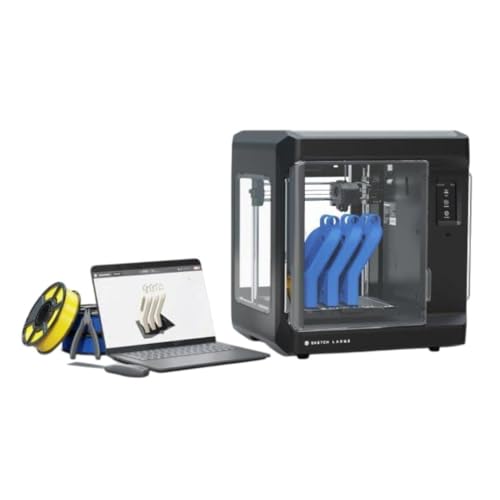
Print Bigger and Bolder: The MakerBot Sketch Large 3D Printer allows you to explore 3D printing on a bigger stage, enable students to design bigger and unhindered on an easy-to-use printer

Enjoy Printing in Multiple Colors: By hooking up as many as four CFS units together, you are able to print in the splendor of 16 colors. Saves the need for extra painting afterward. With Creality Automatic Material System. Intelligent Management of Multiple Filaments

Multicolor Printing with CFS: The K2 Plus Combo includes the K2 Plus 3D printer and one CFS (Color Filament System) unit. The CFS has four slots to hold different filament colors simultaneously. With dynamic mixing, the system enables up to 16-color blending in a single print. Filaments are not included in this combo.
Frequently Asked Questions
Can Astronauts Design and Print Emergency Medical Implants Onboard?
Yes, I can’t currently print certified implants onboard because biocompatibility testing and sterilization chains aren’t fully in place, though I’d use onboard surgical training and future metal/biomaterial validation to safely produce emergency implants.
How Is Intellectual Property Protected When Ground Teams Send CAD Remotely?
I protect CAD uploads with encryption protocols during transfer and storage, and enforce licensing agreements defining use, reproduction, and retrieval rights; I also log access, require authentication, and coordinate legal custody with mission partners.
Can Extraterrestrial Resources (Moon/Mars Regolith) Be Used as Feedstock?
Yes — we can, though I joke regolith won’t brew coffee; regolith recycling and in situ vitrification can turn lunar or Martian soil into usable powder or glass feedstock, enabling structural parts and reduced Earth resupply.
What Are Long-Term Effects of Microgravity on 3D Printer Components?
I’ve found microgravity causes material outgassing, lubrication migration, wear pattern shifts, and particulate buildup that alter tolerances over time, so I inspect seals, reapply lubricants, and test components regularly to guarantee reliable printing.
How Are Printed Parts Certified for Critical Flight Hardware Use?
Like threading a needle through a storm, I make certain parts undergo rigorous qualification testing, destructive and non‑destructive checks, and strict traceability protocols, then document material certifications and flight heritage before approving any critical flight hardware use.