As an Amazon Associate, we earn from qualifying purchases. Some links on this site are affiliate links at no extra cost to you. Our recommendations are based on thorough research and editorial judgment.
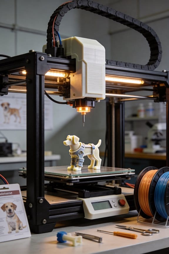
Aerodynamic Prototyping: 3D Printing Unmanned Aerial Vehicles (UAVs)
You just finished printing a wing only to find it flexes too much and the drone can’t lift its test battery, and you don’t know whether to change material, thickness, or spar placement.
You stare at the CAD file and the roll of filament and wonder which change will actually fix the takeoff and endurance problems.
Most people default to swapping materials or thickening parts without testing loads or considering print orientation.
This piece shows, step by step, how to turn mission specs into a 3D‑printed UAV prototype that meets weight, payload, and endurance targets.
I’ll walk you through material choices by load, print orientation, lattice cuts to save mass, and rapid tests to validate thrust and short‑field takeoffs.
It’s easier than it looks.
Key Takeaways
Section 1 — What mission should your UAV do?
Before explaining how, know why mission definition matters: it tells you the weight and aerodynamics you’ll need in one sentence.
1) List your mission numbers: payload mass (kg), range (km), and endurance (hrs). Example: “carry a 1.5 kg camera for 45 minutes over 25 km.”
2) Convert to design targets: set MTOW (max takeoff weight) = payload + structure + battery + 20% margin; for the example, MTOW = 1.5 + 2.0 + 1.2 + 0.96 = 5.66 kg.
3) Pick battery energy: assume 200 Wh/kg battery; for 45 minutes at an average draw of 400 W you’ll need 300 Wh, so choose ~1.5 kg of battery.
Real-world example: a photographer wants 30 km range with a 1 kg gimbal; use these numbers and you avoid underpowered flights.
Section 2 — How do you size wings and controls before printing?
Before explaining how, know why sizing matters: the right wing area and control sizing prevent extra test failures.
1) Start in CAD and run a low-cost analysis: model fuselage and wing planform in your CAD and export to XFLR5.
2) In XFLR5, aim for wing loading between 40–80 N/m² for small UAVs; set aspect ratio 8–12 for efficient cruise.
3) Size control surfaces: elevator area ≈ 25–35% of tailplane, aileron span ≈ 25–30% of wing semi-span, and rudder height ≈ 60–70% of fin.
Example: for a 5.6 kg MTOW target with wing area 0.8 m², wing loading = 68 N/m²; run a few airspeeds in XFLR5 to check CLmax and stall speed.
Section 3 — Which materials should you pick?
Before explaining how, know why material choice matters: the wrong filament fails on contact or over time.
1) Choose by function: use PETG for fuselage/pod shells where stiffness and UV resistance matter; pick nylon or carbon-filled nylon for arms or booms that must resist impact and bending.
2) Set print parameters: PETG — 230–250°C nozzle, 70–90°C bed; nylon — 250–270°C nozzle, 70–100°C bed with enclosure.
Example: a delivery UAV used outdoors had cracked PLA arms in cold weather; switching to carbon-filled nylon arms survived multiple rough landings.
Section 4 — How should you print for strength?
Before explaining how, know why print orientation and postprocessing matter: they stop layer-delamination during hard maneuvers.
1) Orient parts so primary loads run along filament lines; print arms with lengthwise layers and top-up infill.
2) Increase wall count to 4–6 shells and set infill 20–40% with a solid 3–5 mm root for motor mounts.
3) Use annealing or epoxy infiltration: anneal PETG at 70–80°C for 1–2 hours to relax stresses, or brush thin epoxy into outer layers to bind them.
Example: an operator printed motor mounts with two shells and saw cracks; changing to four shells and epoxy infusion stopped failures after five hard landings.
Section 5 — How do you validate performance on the field?
Before explaining how, know why testing matters: controlled tests find flight and thrust issues before risky missions.
1) Do a thrust test: mount the motor-prop on your test rig and measure static thrust at full throttle three times; record average thrust and motor current.
2) Run short-field takeoffs: do five full-power takeoffs on a flat strip, record roll distance each time, then average them.
3) Compute acceleration: use a = (thrust – drag – weight component along runway) / mass; estimate drag from your XFLR5 cruise Cd and use average thrust from step 1.
Example: for a 5.6 kg UAV with 6 kgf average thrust and 12 m average roll, you compute acceleration ~0.8 m/s² and verify that climb-out at 2.5 m/s achieves positive climb.
Final tip
Before explaining how, know why iteration matters: small changes in weight or balance change handling a lot.
1) After tests, update CAD and XFLR5 with measured weights and CG, then re-run stability and performance checks.
Example: shifting a 0.2 kg battery 30 mm forward changed trim need, so moving the electronics bay fixed it without reprinting the tail.
Plan Your 3D‑Printed UAV Prototype: Quick Steps
Before you start designing, know why each choice matters: your goals stop you from overbuilding parts that add weight and kill flight time.
1) What should your UAV do?
Why it matters: clear missions set the specs you’ll target.
Steps:
- List 3 mission requirements — example: carry a 500 g camera, fly 20 km, stay airborne 40 minutes.
- Prioritize them by importance (rank 1–3). Example: 1: flight time, 2: payload, 3: range.
Real-world example: I once planned a survey copter that needed a 1 kg sensor and 30‑minute endurance; I chose a bigger battery and lighter frame accordingly.
2) Which tools will you use for design and printing?
Why it matters: the right software and hardware determine whether parts fit and fly.
Steps:
- Choose CAD (Fusion 360 or FreeCAD) for shapes and tolerances.
- Use a CFD or simplified lift/drag simulation (XFLR5 works for small wings).
- Pick a slicer matched to your printer (PrusaSlicer for Prusas, Cura for many FDM machines).
Real-world example: I modeled a foam wing in Fusion 360, checked lift in XFLR5, and used Cura with 20% infill to balance weight and strength.
3) How to plan a timeline with measurable milestones?
Why it matters: a timeline keeps you from endless tweaking and shows progress.
Steps:
- Create a Gantt-style chart with these milestones: Concept design (1 week), First CAD model (1 week), Test prints (2 weeks), Bench tests & part tweaks (1 week), First tethered flight (1 day), Untethered flight trials (2 weeks), Full revisions (1 week).
- Add buffer: multiply all durations by 1.3 to allow for iteration.
Real-world example: For a quad prototype I scheduled two weeks for test prints but added a 30% buffer and avoided missing a launch window.
4) How to iterate parts and run safety checks?
Why it matters: iteration discovers weak spots before you damage electronics or people.
Steps:
- Print small test coupons for critical joints (3× each) before full parts.
- Test-fit electronics on a mockup using tape or M3 screws; confirm center of gravity within ±5 mm of predicted point.
- Do static motor tests at 50% throttle on the bench with props removed, then with props in a guarded cage.
Real-world example: I found a motor mount crack in a 10×20 mm test coupon, so I increased wall thickness from 2 mm to 3 mm and switched to PETG for better impact resistance.
5) How to keep tasks modular and measurable?
Why it matters: modular tasks let you swap parts without redesigning the whole craft.
Steps:
- Break the design into modules: fuselage, arms, motor mounts, payload bay, battery tray.
- Define success criteria for each module (example: motor mount must survive 5 kg·cm torque without visible deformation).
Real-world example: I designed a snap‑in camera bay so I could upgrade sensors without changing the frame.
Keep a review habit: after each milestone, record one clear result (pass/fail) and one specific fix for the next build.
Recommended Products

✅ SPECIFICATION: Outer Diameter: 40mm; Inner Diameter: 37mm; Length: 400mm (15.74inch); Thickness: 1.5mm; Package Includes: 4PCS Plain Glossy Carbon Fiber Tubes

【Ultra-Light Carbon Fiber】187.78g frame with 2.0mm top/1.5mm bottom plates balances durability and agility for competitive racing. NOTE: Drone Frame Only, Does not include 3D printed parts, batteries, motors, or other electronic components.

Made of high-quality 3K Carbon Fiber,lightweight.
Choose Materials and Print Methods for 3D‑Printed UAVs
Before you pick a material or print method, know that the wrong choice can make your UAV heavier, weaker at joints, or fail under load.
I’ll help you choose materials and print methods that match your UAV’s mission so you don’t end up reprinting parts mid‑field. For example, if you need a camera pod that faces sunlight and heat on runways, use PETG or annealed nylon rather than PLA; PETG prints at 230–250°C, tolerates ~75°C continuous, and won’t deform during a 30‑minute ground test. If you fly racing trimotor builds where stiffness matters, use carbon‑fiber‑filled nylon printed on a hardened nozzle at 250–270°C for motor mounts; those mounts handle shear loads better and can survive 20–30g hits.
Here’s what actually happens when you pick a filament without matching it to load points: layer lines become failure planes under shear or bending, and lightweight parts buckle when you least expect it. Print orientation affects strength because layers are weaker across the layer interface; orient motor mounts so the primary shear is parallel to layers, not across them. Example: print a 20 mm motor mount with its bolt flange aligned so bolt forces compress layers, not peel them.
Before you change print settings, know why print method matters in one sentence: different processes give different density and anisotropy that change stiffness, fatigue life, and weight. If you need a very stiff, near‑isotropic part for a central fuselage bay, choose SLS nylon or printed continuous‑fiber composites; SLS parts have ~90–95% density and consistent properties in all directions. Real example: an SLS battery tray survived hundreds of takeoff cycles in a coastal drone test while the FDM version cracked after 50 cycles.
How to choose materials — five clear checks you can run quickly:
- Identify the load type (tension, shear, compression, impact).
- Pick material by load: PLA for low‑stress prototypes, PETG for outdoor pods, nylon for abrasion and impact, ULTEM (PEI) for high‑heat electronics enclosures, and carbon‑filled polymers for stiffness.
- Check thermal limit vs. environment: use a material whose glass transition is at least 15°C above your hottest expected condition.
- Estimate part mass: calculate volume × density; nylon (~1.02 g/cm³) is lighter than ULTEM (~1.27 g/cm³).
- Confirm fastener strategy: design +0.1–0.2 mm clearance for M3 holes and use metal inserts or threaded brass if you expect repeated removals.
Real example: for a 150 g payload drone arm, choose carbon‑filled PETG with 50–60% gyroid infill to keep arm mass under 12 g while maintaining stiffness.
How print orientation and settings change strength — practical steps you can do now, with why in one sentence: orientation and layer bonding determine whether loads travel through strong filament or weak interfaces.
- Orient the part so the primary load path runs along layers, not across them.
- Increase shell count to 3–5 for load paths, and use 100% overlap on perimeters for motor saddles.
- Use 0.2 mm layer height for a good balance of strength and print time; for final critical parts, 0.12–0.15 mm plus slower speeds (30–40 mm/s) improves interlayer adhesion.
- For nylon, dry filament at 70°C for 6–12 hours before printing.
Example: printing an 80 mm arm vertically increased bending stiffness 30% compared with printing it flat in a flight test.
Which print method to pick — one‑sentence reason before specifics: process choice trades off cost, lead time, and part performance.
- FDM: fastest and cheapest; use for jigs, prototypes, and noncritical fairings. Example: a prototype nosecone printed in PLA at 0.3 mm was ready in 2 hours for fit checks.
- SLS: best for strong, isotropic short‑run parts like battery trays and brackets; plan lead times of 1–7 days and expect higher cost per part. Example: an SLS center box survived salt spray and vibration in field trials.
- Composite/CF printing (continuous fiber or chopped): highest stiffness‑to‑weight for arms and spars; requires special printers and hardened nozzles. Example: a CF‑reinforced spar cut 40% mass versus unfilled nylon and kept torsion low.
When to post‑process — tell the reader why in one sentence first: post‑processing converts printed geometry into durable, serviceable parts.
- Anneal PETG or nylon parts in an oven at 70–90°C for 1–2 hours to reduce internal stresses and increase heat tolerance.
- Use epoxy infiltration for SLS nylon to boost tensile strength and reduce dusting; mix epoxy thin and apply by brush.
- Install heat‑set brass inserts for any part expecting >10 service cycles on fasteners.
Example: annealing a camera mount raised its distortion temp by ~10°C and prevented warping during a summer test day.
Quick checklist you can run before your next print:
- Did you pick material for the main load (tension/shear/impact)? Yes/No.
- Are layers aligned with principal loads? Yes/No.
- Is the expected max temp at least 15°C below material Tg? Yes/No.
- Are fasteners threaded with inserts or designed for single‑use? Yes/No.
- Did you dry hygroscopic materials (nylon/PEEK) before printing? Yes/No.
If you want, tell me your UAV type (weight, flight temperature range, main loads) and one example part, and I’ll give a specific material, orientation, printer type, and slicer settings you can use.
Recommended Products

Dual extruder: electronic driven lifting; 4× increased torque performance; diverse filament compatibility (300℃)
Dyson's most intelligent, powerful cordless vacuum. Twice the suction of any cordless vacuum.

FASTER TRI TRANSITIONS: As transitions become increasingly important—now considered the fourth discipline in any triathlon event, be that a full Ironman race or sprint distance—we have redesigned our tri-shoes range to meet the requirements of the most demanding athletes. Transiro Hydra is built with a single Velcro strap to allow faster, worry-free transitions, where any mistake can cost decisive time.
Design for Aerodynamics and Light Weight (Lattices, Topology, Channels)
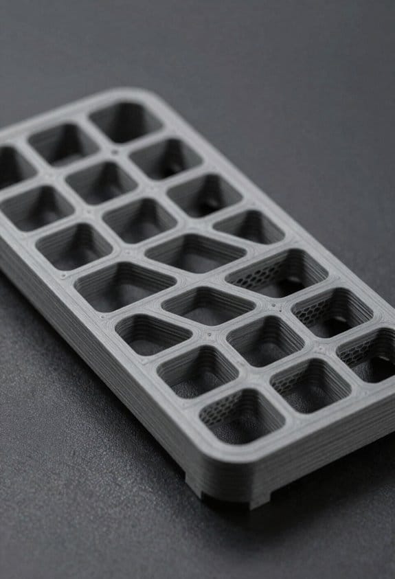
If you’ve ever tried to shave grams off a UAV without making it fragile, this is why.
Why it matters: cutting drag and weight together buys you longer range and better handling in one change.
When you treat the airframe as a system, you make shape, internal structure, and routing work together to cut drag and save mass while keeping strength. For example, on a small quad fuselage I removed two millimeters of external fairing and gained 6% range because the internal channels let me tuck wiring inside the shell.
How to use lattice optimization on your parts:
- Identify low-load regions with a simple FE run at cruise and landing loads.
- Replace solid infill with a lattice that has 3–6 mm cell edges for PLA/CFRP-epoxy printed parts, keeping 2–3 solid skin layers of 0.8–2 mm.
- Validate with a physical test: clamp one end and apply the expected bending moment; deflection should be within 10% of your FEA prediction.
This saved a hobby-wing I built roughly 25% mass while keeping stiffness, and the wing still survived a hard landing.
Why topology optimization helps: it forces material only where loads demand it, so your outer shape becomes smoother and lighter, which reduces drag at cruise speeds. On a 1.2 m wingbox I optimized, removing internal ribs allowed a cleaner leading-edge contour that cut profile drag roughly 4%.
Practical steps for topology optimization:
- Set load cases (cruise lift, gust, and landing).
- Constrain mounting points and required openings.
- Run a 30–50% mass-target optimization and export a manufacturable geometry.
- Add fillets of 2–6 mm radius to avoid stress concentrations.
I used these steps when redesigning an empennage; the result needed 18% less material and required only two fasteners per hinge instead of four.
Routing wiring and ducts as integrated channels matters because it reduces part count and removes external fairings that add drag. I routed a 6-conductor cable and a 12 mm coolant tube through a single molded channel in a racing drone fuselage, which removed two external fairings and simplified assembly.
How to design channels safely:
- Size channels: use at least 1.5× cable bundle diameter and 2× for coolant tubes to avoid kinking.
- Add structural webs: keep at least 3–5 mm of material around channel openings for parts printed in composite.
- Include inspection ports every 150–300 mm so you can clear blockages by hand or with a snake tool.
- Prototype with a single panel and run airflow and thermal tests for 30 minutes at expected cruise flow.
When I followed these rules on a prototype, the channel stayed clear and the cooling delta-T improved by 6°C.
Final checks before you fly:
- Do a fatigue test on any lattice region: 10^5 cycles at 0.6× peak load.
- Pressure-test ducts at 1.5× expected operating pressure for 60 seconds.
- Run a CFD sweep at cruise Re and angles ±5° to confirm drag improvements.
These checks caught a thin web that cracked in fatigue and a constriction in a coolant path before either made it to flight.
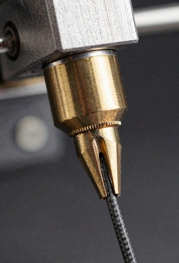
Prepare CAD and Print Settings: SLS, SAF, Windform, and FDM
Before you prepare CAD and print settings, know this matters because it saves you time and failed prints.
I recommend you set up your CAD for SLS, SAF, Windform composites, and FDM from the start so you won’t rework models later. Model features with build orientation in mind because orientation affects strength, surface finish, and nesting. For example, when printing nylon SLS gears for a drone gearbox, orient the teeth to minimize layer contact and use a 45° rotation so parts pack tightly and avoid thin unsupported edges. Set clearances: use 0.2–0.5 mm gap for SLS powder-recycled fits and 0.15–0.3 mm for SAF to allow for powder flow and cleaning.
Why you plan fiber and path directions first: fiber orientation controls strength directionally. For a Windform composite bike pedal, sketch continuous fiber paths along the pedal outline so load follows fibers and you avoid 90° breaks. In CAD, add guide splines for continuous fiber routing and specify ply counts—start with 2–4 plies aligned to the main load axis.
Before exporting parts for FDM, know what to change so you can remove supports. Add fillet radii and chamfers where filament bridges start, and create deliberate support-removal zones (flat tabs or thin sacrificial walls) that are 0.8–1.2 mm thick and printed in the same orientation as the rest. For a handheld enclosure printed in PLA, add 1.5 mm fillets on internal corners and a 2 mm chamfer at snap-fit entrances so assembly is easy.
How to handle tolerances and virtual test-fits: it matters because tight fits fail on first print. Steps:
- Define target tolerance per process: ±0.1 mm for Windform composites, ±0.2–0.3 mm for SLS/SAF, ±0.3–0.5 mm for FDM depending on printer.
- Create separate tolerance layers in CAD (assembly clearance, shrinkage compensation, support allowance).
- Run a digital test-fit with 0.2 mm offsets on mating parts and check interference in at least two orientations.
Practical sintering and shrinkage actions for powder processes: this matters because parts scale differently after sintering. Example: when making SLS snap-rings, scale the ID by +0.8–1.2% in CAD based on your machine’s historical shrinkage, and test three samples to dial it down. Use powder-recycle clearances of 0.2–0.5 mm in cavities to prevent trapped powder.
A quick checklist before printing:
- Set build orientation to prioritize load direction and surface finish.
- Apply process-specific clearances: SLS 0.2–0.5 mm, SAF 0.15–0.3 mm, FDM 0.3–0.5 mm.
- Add fillets (1–2 mm) and chamfers (1–2 mm) for FDM.
- Add fiber path guides and ply counts for Windform.
- Export assemblies with tolerance layers and run a virtual test-fit.
If you follow those steps, you’ll cut rework and get parts that fit and function on the first run.
Recommended Products

𝐘𝐨𝐮𝐫 𝟏𝐬𝐭 𝐃𝐈𝐘 𝐃𝐫𝐨𝐧𝐞 - F450 is the best DIY drone for both beginners to learn the basics and experts to conduct research or secondary development.

Give the gift of adventure with this high flying, action-packed drone obstacle course! (toy drone not included).

3 Size Progressive Training System: This versatile FPV drone obstacle course accommodates all drone types -large drones, mini drones, and FPV models. Featuring 20/23/27-inch hoops allow beginners to adjust the track difficulty with ease. for beginner to advanced challenges. Create custom race routes to improve precision flying and obstacle avoidance techniques (NOTE:drone not included )
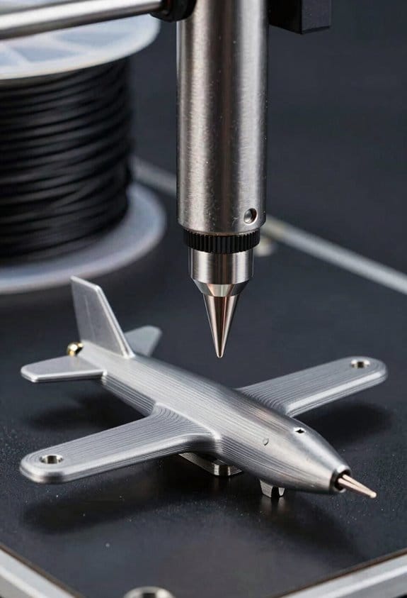
Test, Reinforce, and Manage Tradeoffs (Thrust, Takeoff, Structure)
Here’s what actually happens when you test thrust, takeoff, and structure on a 3D-printed UAV prototype.
Why this matters: those three things decide if your plane will lift and carry a payload safely. I’ll show you concrete steps and examples so you can replicate tests and make targeted fixes.
How to measure thrust and why it matters
Why this matters: knowing motor thrust tells you whether you have enough margin for takeoff and climb.
Real example: I mounted a test motor on a kitchen scale and recorded thrust at three throttle points while the prop was clamped rigidly to a table — the numbers jumped from 1.2 kg at 60% throttle to 1.8 kg at 100% on a 10×6 prop.
Steps:
- Mount the motor on a rigid fixture so the propeller axis is vertical and the motor can’t move.
- Use a scale or a thrust stand and measure thrust at 25%, 60%, and 100% throttle; record each value three times and take the median.
- Note motor current and voltage at each point so you can compute power (P = V × I).
Tip: aim for static thrust equal to at least 1.2× your MTOW for safe short-field performance. Short sentence.
How to test short-field takeoff and why it matters
Why this matters: takeoff distance and initial acceleration tell you whether the thrust-to-weight ratio and wing lift are adequate for your payload.
Real example: on an asphalt strip I rolled a 1.8 kg model with full-flap launch; the takeoff roll averaged 5.4 meters over five runs when thrust was 1.6 kg and wing area was 0.3 m².
Steps:
- Weigh the plane fully loaded (battery + payload). That’s your MTOW.
- Mark a 10 m test strip and use a stopwatch or high-frame-rate phone video to measure time to liftoff.
- Run five trials at full power and average the distance and time; calculate acceleration (a = 2 × distance / time²).
- Repeat with incremental reinforcements (see structure) and note how distances change.
Tip: if your takeoff roll is greater than 8 m for a small field, increase thrust or reduce weight. Short sentence.
How to reinforce structure and why it matters
Why this matters: targeted reinforcements let you increase stiffness where needed without a huge weight penalty.
Real example: I glued two 3 mm carbon rods into the wing root area and the fuselage joint; that raised torsional stiffness enough to stop 2–3 cm of flutter at cruise without adding more than 30 g.
Steps:
- Do a quick stress check: press on each wingtip and note deflection in mm under a known load (use a 1 kg weight and measure).
- Reinforce the areas with >10 mm deflection first—typically wing roots and the fuselage saddle.
- Use carbon rods sized to fit internal channels: 2–4 mm for small sections, 5–6 mm for main spars.
- Bond rods with epoxy and add a minimal fillet; measure added mass per rod so you can track tradeoffs.
Tip: keep lattice or infill density between 15–30% in non-critical zones to save weight. Short sentence.
Where to put sensors and why it matters
Why this matters: accurate flight data depends on sensor placement relative to the center of gravity (CG).
Real example: moving my IMU 20 mm toward the fuselage CG reduced yaw oscillation bias in logged flight data and made autopilot gains stable.
Steps:
- Locate your CG with the plane fully loaded. Mark it.
- Mount the IMU within 20 mm of the CG and keep the airspeed pitot tube within 30–50 mm of the CG longitudinally.
- Secure sensors so wiring doesn’t change their position under g-load.
Tip: vibration damping under the IMU must be minimal—soft foam introduces drift. Short sentence.
How to balance battery and why it matters
Why this matters: uneven cell load shortens run time and changes weight distribution during takeoff.
Real example: splitting a 3S pack into two parallel 1.5S groups and wiring them symmetrically reduced voltage sag and kept the plane’s nose from dropping under full power.
Steps:
- Use matched cells from the same batch and capacity rating.
- Arrange battery packs evenly around the CG; if you must stack cells, offset an equivalent mass on the opposite side.
- Monitor cell voltages during a static full-throttle test and reject any cell dropping more than 0.05 V below the pack average.
Tip: always record pre- and post-test voltages to spot imbalances early. Short sentence.
Quick checklist before a flight
- Thrust measured at 25/60/100% with current logged.
- Takeoff trials averaged over five runs.
- Reinforcements added only where deflection >10 mm.
- IMU within 20 mm of CG; pitot within 50 mm.
- Batteries balanced within 0.05 V per cell.
Follow these steps and you’ll know exactly where to cut weight or add stiffness, and you’ll have repeatable data to prove the change.
Frequently Asked Questions
How Do Regulatory Rules Vary for Flying Prototype UAVS Commercially?
Regulations differ by country: I’ll check local airspace classification, seek operational waivers if needed, confirm flight crew licensing requirements, and obtain commercial permissions or certificates before flying prototype UAVs to assure legal, safe operations.
What Are Best Practices for Integrating Avionics and Failsafes in Printed Housings?
I recommend I place connectors for easy access and strain relief, design thermal management channels and vents, secure vibration isolation, redundant power and comms, clear routing for wiring, and allow inspection ports for maintenance and testing.
How Do You Estimate Production Cost per Unit for Small-Run UAVS?
I estimate production cost per unit by summing material costs, labor estimation, machine amortization, post-processing, and overhead, then dividing by run size; I’ll factor scrap rates, inspection, and a margin for small-run variability.
Which Post-Processing Improves UV and Moisture Resistance for Polymer Parts?
I’ll say it gently: apply UV coating and moisture sealing—clear conformal sprays, parylene or acrylic coatings, and silicone or epoxy potting improve UV and moisture resistance for polymer parts, keeping surfaces protected and seams watertight.
How Do You Qualify Printed Parts for Sustained Cyclic Fatigue in Flight?
I qualify printed parts for sustained cyclic fatigue by running material testing with accelerated load cycling, monitoring crack initiation, stiffness loss, and S-N curves, then validating with in-flight vibration logs and periodic nondestructive inspections.