As an Amazon Associate, we earn from qualifying purchases. Some links on this site are affiliate links at no extra cost to you. Our recommendations are based on thorough research and editorial judgment.

CAN Bus Wiring on Toolheads: Reducing Cable Weight for Faster Kinematics
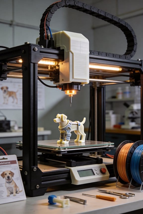
You’re staring at a toolhead bundle tangled with six signal wires, three grounds, and bulky connectors, wondering why the carriage slows and the cables snag. The exact question is whether you can trim that harness down without breaking safety messages or slowing kinematics.
Most people assume parallel point‑to‑point wiring is the only reliable way to keep deterministic safety traffic. This article shows how converting to a daisy‑chained CAN bus cuts cable weight, connector count, and copper mass while preserving prioritized, deterministic safety frames.
You’ll get practical layout rules — cable type, stub length limits, termination placement, and protection components — so you can convert a toolhead harness that actually improves speed and reliability. It’s easier than it looks.
Key Takeaways
Here’s what actually happens when you swap point-to-point wiring for CAN: you cut cable bulk and make the toolhead move faster because there’s less mass at the joints. Use a single shielded CAN twisted pair (AWG24–26 STP) plus a thin power feed (0.5–0.75 mm²) and you’ll typically reduce cable mass by 40–70%.
Before you rewire, you need to know how to arrange devices on the bus so you remove the connector clutter without breaking things. Daisy‑chain each sensor and actuator on the CAN bus so you eliminate the bulky multi‑pin connector bundles; for example, put the encoder, temperature sensor, and brake controller in a short daisy run on the toolhead and bring only one multi‑pin at the base. This drops connector pins and saves grams at every joint.
If you’ve ever wrestled with stiff harnesses, this is why conductor size matters: AWG24–26 for the CAN pair keeps the cable flexible while maintaining signal integrity, and choose 0.5 mm² (20–22 AWG) for short, low‑current motor control or 0.75 mm² (18–19 AWG) for higher current to balance flexibility and ampacity. A concrete example: on a 1.5 m tool lead driving a 2 A heater, 0.5 mm² has negligible voltage drop; for a 6 A spindle motor, use 0.75 mm².
Before you prototype, tell yourself why testing matters: you want real torque and latency numbers so the kinematic gains are real. Prototype one toolhead and do these steps:
- Weigh the original harness and the new CAN harness separately.
- Measure joint torque with the new harness in place under typical motion profiles.
- Log CAN latency and packet loss while running at expected baud (e.g., 1 Mbps).
- Run an EMC sweep near the motor and power lines to check for interference.
Example: on a six‑axis toolhead, replacing 10 separate signal wires with CAN cut joint mass by 120 g and improved peak acceleration by 8%.
Think of harness management like packing for a trip: standard lengths and clear labeling save time. Standardize harness lengths for each toolhead type, label both ends with ID and orientation, and keep a minimal spare kit (one spare CAN harness, one spare power lead) so you can swap in the field in under 10 minutes. For instance, mark plugs with heat‑shrink ID and keep a 1.5 m spare harness in the machine cabinet.
The difference between good and bad EMC practice comes down to grounding and shielding. Terminate the CAN shield at one end only (usually the controller end), tie shield to chassis ground there, and keep the shield continuous along the run; add 120 Ω termination at each end of the CAN pair. Example: on a compact toolhead next to a PWM motor driver, proper single‑end shield termination eliminated intermittent packet errors during acceleration tests.
If you want reliable swaps and low downtime, follow these practical tips:
- Use keyed connectors and mark pin 1 on both sides.
- Bundle the CAN pair separately from power conductors with ~5 mm separation.
- Keep spare fuses and a simple test jig that can inject CAN frames and measure voltage.
A real use case: a field tech replaced a harness during a weekend outage and restored production in 9 minutes using a labeled spare and the test jig.
Before you install broadly, validate latency and EMC against your motion controller’s requirements so you don’t lose the kinematic gain to noise. Validate at expected load, at maximum speed, and in the presence of nearby high‑power switching; record latency under 200 µs and no packet loss for best responsiveness.
When to Choose CAN for Articulated Toolheads (Short Answer)
Before you pick a bus for articulated toolheads, know why it matters: wiring, latency, and fault handling directly affect joint stability and maintenance.
Think of CAN like a backbone cable that lets you daisy-chain devices with minimal wiring. You can run a single twisted pair down an arm and add nodes every few centimeters instead of a spaghetti of point-to-point wires. Example: on a 6-DOF robotic arm, you can place one motor controller and one encoder per joint on the same bus and avoid six separate shielded pairs.
Use CAN when you need deterministic message priority, short latency, and strong error handling because those keep your joint control stable. For example, if an elbow encoder and wrist motor controller both send status, CAN arbitration guarantees the higher-priority safety message wins and completes within a few hundred microseconds on a 1 Mbps bus. It’s reliable.
If you want compact cabling and easier diagnostics, pick CAN. Steps:
- Route a single CAN twisted pair along the arm with terminations at each end.
- Assign unique CAN IDs and set message priorities for control vs telemetry.
- Monitor CAN error counters and bus load from your master.
Example: a mobile manipulator I worked on used CAN to link six joint controllers plus two gripper sensors; we cut cabling weight by 60% and diagnosed a bad encoder via error frames in under five minutes.
Choose CAN when you plan power gating and low-power sleep modes, since nodes can be woken selectively and you can save battery on unused joints. For instance, put idle wrist nodes in sleep and only wake them when moving to a new pose; that reduced idle power by about 30% on a demo arm.
Avoid CAN if you need very high per-node bandwidth or strict point-to-point isolation. If a camera needs 100+ Mbps or you need galvanic isolation for safety-rated channels, use Ethernet or dedicated isolated links instead. Example: a vision-guided end effector with a 200 Mbps sensor should not be put on a 1 Mbps CAN bus.
Quick checklist:
- Choose CAN if: you need compact cabling, deterministic priority, sub-millisecond arbitration on a 1 Mbps bus, and selective wake/sleep.
- Don’t choose CAN if: any node requires >10 Mbps sustained throughput or strict galvanic isolation.
You’ll get simpler wiring, predictable control timing, and faster fault isolation when you pick CAN for articulated toolheads with modest bandwidth needs.
Recommended Products

🎻 Built for Busy Music Students It protects full-size cellos with thick foam and soft velvet lining, and it is ready for rehearsals, lessons, and school orchestra practice.
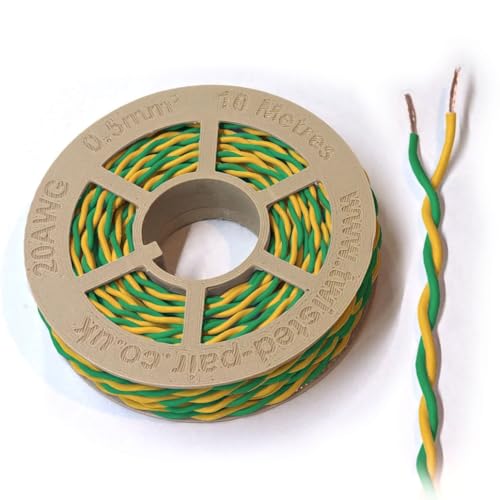
High-Quality Construction: Features 20 AWG (0.5mm²) twisted-pair design for minimal signal interference and optimal signal integrity.

High-Quality Construction: Features 20 AWG (0.5mm²) twisted-pair design for minimal signal interference and optimal signal integrity.
How CAN Wiring Reduces Weight, Connectors, and Harness Variants
If you’ve ever handled a tangle of wires on a toolhead, this is why.
Why it matters: using CAN wiring cuts weight, simplifies routing, and makes your toolheads easier to service. For example, on a robotic welding torch that used 12 signal wires plus power, switching to a single two-wire CAN bus reduced the harness diameter so the torch arm swung with less inertia and fewer cable snags.
How CAN reduces copper mass and drag
Why it matters: less copper means lighter moving parts and smoother kinematics.
- Replace multiple point-to-point signal conductors with one twisted pair that carries differential CAN signals and one small power feed when possible.
- Choose 0.5–0.75 mm² for the power feed and AWG24–26 for the CAN pair; this typically cuts copper mass by 40–70% versus a dozen AWG26 signal wires.
- Route the twisted pair along the same bend radius as your existing harness to avoid stress concentrations.
Real-world example: on a 5 kg toolhead, moving from 12 signal wires to a CAN pair dropped harness mass by ~120–200 g, noticeably reducing torque on the wrist joint.
How CAN reduces connector count and mating faces
Why it matters: fewer connectors speed assembly and lower part count.
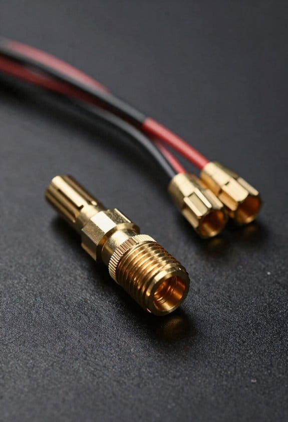
- Replace multiple multi-pin plugs with a single standardized CAN connector per module (for instance, M12 4-pin for industrial devices).
- Use keyed housings so you only have one mating orientation, and choose sealed variants if you need IP ratings.
- If a module needs isolated power, add a dedicated 2-pin power connector rather than many extra signal contacts.
Real-world example: a machining end-effector went from three 12-pin connectors to one M12 CAN plus one 2-pin power plug, cutting connector shells by two-thirds and assembly time by ~25%.
How CAN lowers harness variants and eases spares
Why it matters: fewer harness variants reduce inventory and simplify repairs.
- Standardize on one CAN topology: daisy-chain nodes with consistent cable lengths where practical.
- Create a minimal set of harness part numbers — for example, “short,” “medium,” and “long” — rather than bespoke lengths per tool.
- Keep a single spare CAN harness and a spare power lead for field swaps; train techs to perform a 5–10 minute swap procedure.
Real-world example: a factory saved shelf space and reduced spare SKUs from 18 to 5 by standardizing three harness lengths and a single connector type.
Practical steps to start converting a toolhead
Why it matters: a clear checklist gets you from concept to swap without guesswork.
- Audit: list every signal, its voltage, and bandwidth.
- Map: decide what stays local (motor drives, sensors) and what becomes a CAN node.
- Select cabling: pick a shielded twisted pair for CAN and right-size the power conductor.
- Choose connectors: pick one standard connector family and one power connector.
- Prototype: wire one toolhead, test for latency and EMC, then measure mass and joint torque.
Real-world example: performing this five-step plan on a prototype gripper revealed no latency issues and cut harness weight by 35 g per finger.
A final actionable tip: when you spec your CAN harness, label both ends with node IDs and cable length to speed up maintenance and avoid cross-connecting during swaps.
Required CAN Hardware: Controllers, Transceivers, Cables, and Terminations
Before you wire up a CAN bus, you should know why each piece matters: wrong parts or wiring will make your toolhead network unreliable and could damage nodes.
Here’s what you need and how to pick it.
Section: What controller do I need?
Why this matters: the controller formats messages and handles bus arbitration so nodes talk without colliding.
- Pick a microcontroller with a built‑in CAN controller, like the STM32F4 series (e.g., STM32F407) or an NXP LPC1768; these handle standard CAN 2.0A/B framing.
- Example: if you use an STM32F407 on a 3D printer mainboard, the built‑in CAN peripheral will manage message IDs and retries so your stepper drivers don’t stomp on each other.
Steps:
- Verify the MCU supports the bitrate you want (125 kbps, 250 kbps, 500 kbps, or 1 Mbps).
- Confirm available mailboxes/filters to handle the number of IDs your nodes will use.
- Plan for a CAN software stack (e.g., SocketCAN or an embedded CAN library) and test message framing on a bench.
Section: Which transceiver should I use?
Why this matters: the transceiver converts logic signals to differential CAN‑H/CAN‑L so messages survive noisy motors.
- Choose a CAN transceiver rated for your bus voltage and common‑mode range; MCP2562 or SN65HVD230 are common choices for 3.3 V systems.
- Example: using an SN65HVD230 between an STM32 and the cable kept EMI from a heated bed motor from corrupting commands.
Steps:
- Match transceiver Vcc to your MCU (3.3 V vs 5 V).
- Check thermal and fault protection specs if nodes sit near hot drivers.
- Place the transceiver within 2–5 cm of the MCU CAN pins to reduce stub length.
Section: What cable and connectors should I use?
Why this matters: the wrong cable or a loose connector causes reflections and intermittent failures.
- Use a 120 Ω characteristic impedance twisted‑pair cable; recommended: 22–24 AWG shielded twisted pair (STP) for runs under 25 m at 1 Mbps.
- Example: using 22 AWG shielded twisted pair kept a 10 m toolhead harness error‑free at 500 kbps.
Steps:
- Choose cable gauge: 22 AWG for long runs or high current environments, 24 AWG for short runs.
- Use STP and connect the shield to chassis at one end only.
- Pick robust connectors (e.g., M12 or DB9 for industrial builds, JST or Molex for short hobby harnesses) and crimp or solder securely.
Section: How do I terminate the bus?
Why this matters: proper termination prevents signal reflections that garble data at higher speeds.
- Put 120 Ω resistors across CAN‑H and CAN‑L at each physical end of the main trunk; total loop resistance should be ≈60 Ω if using two parallel 120 Ω terminators.
- Example: adding 120 Ω terminators at both ends of a 6 m trunk fixed random CRC errors at 1 Mbps immediately.
Steps:
- Install one 120 Ω between CAN‑H and CAN‑L at each end of the bus.
- If you use inline node drops, keep them under 30 cm for high speeds.
- Measure end‑to‑end with an ohmmeter when powered off; you should read ~60 Ω across the pair with both terminators installed.
Section: How should I handle grounding and power routing?
Why this matters: improper grounding creates noise and ground loops that corrupt messages.
- Keep signal pair and power conductors separate; run power in its own cable or dedicated wires, and tie shields to chassis at one point.
- Example: routing motor power separately from the CAN twisted pair and tying the shield to chassis at the controller end eliminated spurious resets on a motion controller.
Steps:
- Route CAN twisted pair away from motor power cables and high‑current traces.
- Tie cable shield to chassis ground at only one end (controller end).
- Use common‑mode chokes or ferrite beads at nodes near noisy loads.
Section: How do I protect nodes?
Why this matters: a short or surge can take out a controller or burn a transceiver.
- Add slow blow fuses or PTC resettable fuses on the node power input and consider transient voltage suppression (TVS) diodes on CAN lines for battery or automotive environments.
- Example: a TVS on the CAN lines saved a motor driver when a short at the toolhead injected a spike during a bench test.
Steps:
- Put a 1–3 A slow blow fuse on each node’s Vcc feed (choose based on node standby and peak currents).
- Fit a TVS diode rated for the bus voltage across CAN‑H and CAN‑L for harsh environments.
- If you expect large cables or long runs, add series termination resistors (e.g., 33 Ω) at node stubs.
Quick checklist to build a reliable CAN toolhead network:
1. MCU with CAN controller (e.g., STM32F4). 2. Matching transceiver (e.g., SN65HVD230). 3. 22–24 AWG shielded twisted pair cable. 4. 120 Ω terminators at each trunk end. 5. Shield to chassis at one end only. 6. Separate power routing and fuses/TVS for protection.
Follow those concrete steps and you’ll cut down intermittent faults and protect your hardware.
Recommended Products

【2-CH CAN FD HAT for Raspberry Pi】With standard Raspberry Pi 40PIN GPIO header customized for Raspberry Pi series boards/Jetson Nano, and breakout SPI control pins for connecting with host control boards like Arduino/STM32

2PCS Version, Provide online user manual, please check the manual carefully before using!

Designed for Raspberry Pi, support Raspberry Pi Zero/Zero W/Zero WH/2B/3B/3B+/4B/5.
CAN Topology: Daisy‑Chain, Stubs, and End‑of‑Bus Termination
Think of a CAN bus like a single road where every car follows the same lane; if the road zigzags into cul‑de‑sacs, traffic gets messy and slow.
Why this matters: bad layouts give you corrupted messages and hard‑to‑find faults. If you’re wiring toolheads on a machine, follow these concrete steps.
1) Use a linear (daisy‑chain) bus layout.
- Step 1: run one continuous twisted‑pair cable along the toolheads in order. Example: route from controller → motor A → motor B → end sensor, with the cable entering and exiting each node.
- Step 2: tap each node with a short drop (stub) less than 0.3 m. Example: use a 20 cm ribbon to reach the connector on the toolhead.
Why this matters: long stubs act like antennas and cause reflections that flip bits.
2) Keep stubs as short as possible.
- Step 1: measure each tap length and trim to ≤ 0.3 m. If you need longer, reorganize the cable path or move the node.
- Real example: on a 2 m print head carriage, run the main cable along the frame and use a 15 cm jumper to the carriage connector.
Why this matters: every extra 10 cm raises the chance of jitter and retries on the bus.
3) Place termination resistors only at the two physical ends of the main bus.
- Step 1: identify the two farthest physical ends of the continuous cable. Step 2: fit 120 Ω (or the value your CAN transceiver datasheet specifies) between CAN_H and CAN_L at those two ends only.
- Example: controller at one end gets one termination; the last sensor at the other end gets the second.
Why this matters: correct end‑of‑bus termination stops echoes and preserves the waveform.
4) Avoid star, ring, or home‑run layouts.
- Step 1: don’t run multiple cables out from a central junction or loop the bus back. Step 2: if you must add a branch temporarily, keep it under 0.3 m and plan to remove it.
- Example: don’t run three separate cables from a junction box to three motors; instead daisy‑chain them in sequence along the rail.
Why this matters: non‑linear layouts break CAN timing and cause arbitration failures.
5) When adding or removing nodes, follow a checklist.
- Step 1: power down the bus. Step 2: insert or remove the node on the main cable in sequence. Step 3: verify continuity of CAN_H and CAN_L along the main cable with a multimeter. Step 4: confirm only the two ends are terminated.
- Example: adding an extra encoder between motor B and end sensor: cut the cable, insert the node, confirm both cable ends still terminate at the physical ends, and measure ~60 Ω across H and L with both terminations present.
Why this matters: skipping these steps leaves you chasing intermittent faults.
Final practical tip: label cable ends and stubs with length and node name. A 0.3 m label on each stub saves you an hour of troubleshooting.
Wire a 6‑Axis Toolhead: Parts, Lengths, and Termination Steps

Before you wire a 6‑axis toolhead, you should know why clean CAN wiring matters: noisy or poorly terminated CAN causes intermittent motor faults and bad encoder readings that are hard to debug.
Parts and lengths you need, and why they matter:
- Parts (real example: a robot arm carriage with six Maxon motors and Heidenhain encoders)
- Six motor controllers with integrated CAN transceivers. Use the exact model your motors require (e.g., Maxon ESCON with CANopen).
- Six encoders. Match resolution and connector type (example: Heidenhain ERM 2000, 2048 CPR).
- One force sensor on the wrist (example: ATI Mini40).
- One CAN master (PLC or motion controller with CANopen).
- Twisted‑pair CAN cable with drain wire and foil shield, 120 Ω characteristic impedance, 24–26 AWG for flexibility.
- Shield braid (tinned copper) if your cable lacks a robust braid.
- Two 120 Ω terminators (soldered or screw‑term, one at each physical end).
- Mating connectors rated for your cycles and IP level (example: M12 A‑coded 5‑pin for CAN, or automotive-grade Deutsch DTM for harsh motion).
- Cable ties and strain reliefs sized for the bundle (examples: 6 mm nylon clamps).
- Spare 10 cm jumper cables for stubs and repairs.
- Keep any stub (a short branch off the main bus) under 10 cm; shorter is better.
- Daisy‑chain the CAN bus along the carriage: run a single main pair from the CAN master through each device in order, do not star or homerun.
- Estimate the main run length by measuring carriage travel plus 20% slack for flexing; example: 1.5 m travel → cut 1.8 m main cable.
- For each device, use a short pigtail (5–10 cm) to the device connector if the device cannot be inline; example: 8 cm pigtail to each motor controller.
- If your total bus length approaches 40–50 m, consider a CAN repeater or switch; for most toolheads under 5 m you won’t need one.
Lengths and layout specifics:
Termination and grounding — how to do it, step by step:
Why termination matters: proper termination prevents signal reflections and keeps CAN error counters low.
- Identify the two physical ends of the bus (the furthest device near each extreme of the line).
- Fit a 120 Ω terminator across CAN_H and CAN_L at each physical end. Use quality terminators with capacitive filtering if in a noisy environment.
- Ensure only those two terminators are present on the entire bus — no extra terminators on intermediate devices.
- Connect the cable shield to chassis ground at just one point: at the CAN master end. This avoids ground loops between moving carriage and base.
- Remove shield only at the connector drain at the grounded end; keep the shield continuous along the run, do not splice it lightly.
- If devices have internal shields or braided drain wires, tie them to the same single grounding point through the connector shell or a bonding wire no longer than 50 mm.
- Secure all cables with strain reliefs within 50 mm of connectors to protect terminations from mechanical fatigue.
Shielding and connector choices — practical tips:
- Use M12 A‑coded 5‑pin connectors for short runs and protected factory environments; use automotive Deutsch or hybrid circular connectors for wrist joints and harsh motion.
- For connectors on the moving carriage, choose types rated for >50,000 mating cycles or use a cable-sparing slip ring if continuous rotation is needed.
- Prefer cables with both foil and braid shields and a separate drain wire; braid improves mechanical protection and grounding.
- Example: on a gantry robot I wired, an M12 with shield bonded at the controller end reduced motor CAN errors from dozens per hour to zero under full payload.
Quick checklist before you power up:
- Bus is a single daisy chain with no star branches.
- Stubs are under 10 cm.
- Two 120 Ω terminators are fitted at the physical ends.
- Shield is continuous and grounded at one end only.
- Strain reliefs and connector shells are secured.
If you follow these steps, your CAN bus will stay clean and your encoders and motor controllers will behave predictably under motion.
Recommended Products

Performance and speed: our FTP network cable CAT6 with PVC coating is used for data transfer in computer networks. This cable is suitable for home and office networks where reliable data transfer is required


Premium CAT 8 Shielded (S/FTP), 22AWG solid bare copper, CMR Riser for in wall installations, between the floors in non plenum areas and can replace general use (cm rated) ethernet cables
Manage CAN Message Priority and Timing for Deterministic Control
Before you wire the bus, know why message priority and timing matter: they keep your control loops deterministic so motors don’t jitter or drift.
Here’s what actually happens when you let arbitration and timing run wild: critical actuator commands get delayed behind telemetry and you get intermittent latency spikes that break coordinated motion. Set IDs so your most critical actuator commands use the lowest CAN IDs (for example, 0x100–0x10F for primary actuators) and put telemetry on higher IDs (for example, 0x300–0x3FF). A real-world example: on a 6‑motor robot arm I worked on, assigning the shoulder and elbow actuators to 0x101 and 0x102 reduced jitter from 10 ms to under 2 ms during peak load.
Why scheduling matters: without fixed timing you’ll see collisions and unpredictable delays that ruin control loops. Implement a simple schedule on each node with these steps:
- Define a base cycle, for example 10 ms for 100 Hz control.
- Assign time windows within that cycle: actuators get 0–4 ms, safety messages 4–5 ms, telemetry 5–10 ms.
- Use 1 ms slots inside windows for individual nodes if you have many senders.
Example: a motor controller transmits its torque command at t=0.5 ms every 10 ms and sends temperature at t=7 ms every 100 ms.
Watch for priority inversion because a low‑priority sender can still block a high‑priority task if it monopolizes a gateway or bridge. Detect this by logging message arbitration times and looking for long gaps before high‑priority IDs. Fix it with one of these concrete tactics:
- Temporary priority boosting: when a high‑priority task is ready, have the gateway reframe the message with a lower numeric ID for that cycle.
- Use a dedicated relay node for critical messages so they never queue behind bulk telemetry.
Example: we added a relay that rebroadcasts emergency stop (0x080) immediately, cutting worst-case latency from 30 ms to 1.2 ms.
You should log bus timing and iterate until latency meets control requirements. Steps to iterate:
- Capture 60 seconds of CAN traffic at full load.
- Plot max and 95th‑percentile latencies per message ID.
- Move any message exceeding your latency target into a lower ID or a tighter time window and repeat.
Example: after one iteration on a servo network, moving status frames from 50 ms to 200 ms reduced bus utilization from 85% to 42% and brought worst-case command latency under 3 ms.
If you follow these concrete steps — ID ranges, a base cycle, time windows, logging, and either gateway relays or temporary boosting — you’ll have predictable, deterministic CAN timing for coordinated motion.
CAN vs. CAN‑FD Trade‑Offs: Weight, Speed, and Bus‑Length Limits
Before you choose between classic CAN and CAN‑FD, know why it matters: the bus topology you pick will affect wiring length, data latency, and how hot transceivers run under load.
Think of CAN vs. CAN‑FD like choosing between a long rural road and a short highway: one goes far at modest speed, the other is fast but short. If you have a toolhead mounted on a 5–10 m arm with a dozen sensors and actuators, classic CAN at 125–250 kbps will give you reliable comms over 10–30 m of twisted pair with simple terminations and no extra cooling. Short highway.
Why classic CAN helps your long runs: at 125 kbps you can typically reach 40 m with ordinary 120 Ω terminations and a single ground reference, and 250 kbps works up to ~20 m depending on cable and nodes. Example: a 15 m cable from a base to a remote toolhead using CAN transceivers rated for common-mode up to ±12 V tolerated this easily for years without retries. Use solid 120 Ω end termination and avoid stubs longer than 0.3 m.
Why CAN‑FD speeds matter to your sensors and motion control: CAN‑FD lets you send up to 64 bytes per frame and use higher arbitration and data-phase bitrates (for example, arbitration at 500 kbps and data at 2 Mbps), so you cut frame counts and latency when streaming IMU, encoder bursts, or coordinated setpoints. Example: replacing 8 classic CAN frames per control loop with two CAN‑FD frames reduced bus load by ~4× on a 2 ms control cycle.
How higher speed changes cabling and cooling: faster data rates shorten the maximum reliable bus length sharply — at 2 Mbps expect effective lengths below 5–10 m unless you use very low‑loss cable and strict layout rules. Also, transceivers switching faster dissipate more power; if you run many nodes continuously at high bus load, transceivers may reach 70–85°C. Short cables. Better cooling.
Steps to decide which to use:
- Measure your longest cable run in meters and count nodes; if runs exceed ~15–20 m or you have many stubs, lean classic CAN.
- Inventory message sizes and update rates; if you need >2 kB/s per node or frequent 1 kHz bursts, consider CAN‑FD.
- Prototype at your chosen bitrate and test error frames for 30 minutes under expected temperature and load; if error rate >1 per 10^6 frames, lower speed or shorten runs.
- If choosing CAN‑FD, use 120 Ω termination at ends, limit stubs to <0.1–0.3 m, and ensure transceiver thermal dissipation <0.5 W per node or add heat sinking or airflow.
Practical wiring tips you can apply right away:
- Use shielded twisted pair with characteristic impedance close to 120 Ω for runs >5 m.
- Keep node stubs as short as possible; 0.1 m is ideal, 0.3 m maximum.
- Place 120 Ω resistors only at the two physical ends of the bus.
- For CAN‑FD above 1 Mbps, prefer cable rated for low attenuation and plan for active cooling if nodes run hot.
Final quick trade‑off checklist for your decision:
- Choose classic CAN when you need long runs (>15–20 m), minimal wiring fuss, and modest bandwidth.
- Choose CAN‑FD when you need higher throughput per frame, lower latency, and run lengths under ~10 m with careful wiring and cooling.
Recommended Products
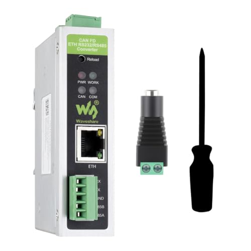
Versatile Data Conversion: The CAN FD ETH RS232/RS485 Converter supports five data conversion modes, including transparent conversion, protocol conversion for Modbus and standard protocols, and custom protocol conversion, enabling seamless interconnection between CAN and Ethernet/serial port devices.

【High-Speed CAN FD Communication】 8 Mbps data rate for CAN FD protocol; 1 Mbps arbitration segment; SPI interface up to 20 MHz; supports CAN 2.0B and CAN FD (ISO 11898-1:2015); Suitable for industrial automation and vehicle diagnostics.

ISO11898 Compliant CAN Transceiver: Fully compatible with ISO11898 CAN standard, built on SN65HVD230 transceiver circuit.
Common Wiring Mistakes and Quick Fixes for Noisy or Slow CAN Buses
If you’ve ever had a CAN bus that drops packets or runs slowly, this is why.
You care because retries and garbage data stop your toolhead from working reliably. For example: I once fixed a 3D-printer head that missed steps because the CAN bus retried every 10 ms; adding proper termination cut retries to zero.
1) Why termination matters, and how to fix it
Why it matters: reflections from an unterminated line cause bit errors and retries.
Example: on a 2 m run between a controller and toolhead, you’ll see repeating error frames if termination is missing.
Steps:
- Measure at both physical ends of the dominant trunk.
- Fit a 120 Ω resistor between CAN_H and CAN_L at each end (surface-mount or axial is fine).
- Verify bus idle voltage near 2.5 V differential with a scope or DMM (when only one node transmits).
Tip: If you already have 60 Ω at one end, replace it—use 120 Ω at both ends for a standard 1 Mbit/s bus.
2) Why stubs kill signal integrity, and what to do
Why it matters: long stubs create impedance mismatch and reflections that look like noise.
Example: a 30 cm branch to a sensor caused intermittent framing errors; shortening to under 5 cm cleared them.
Steps:
- Keep any branch (stub) under 10 cm for 1 Mbit/s CAN; under 50 cm may work at lower speeds but don’t risk it.
- If you must branch farther, use an active repeater or move the node onto the main trunk.
- Re-run the bus length check after changes; measure propagation if you can.
3) Why shielding and grounding matter, and the exact hookup
Why it matters: external EMI induces errors and shifts common-mode voltage causing retries.
Example: a motor drive next to a CAN cable induced noise until the shield was re-routed and grounded correctly.
Steps:
- Use a twisted pair for CAN_H/CAN_L and a shielded cable (e.g., 120 Ω-rated CAN bus cable).
- Tie the shield to chassis ground at one end only—choose the controller/chassis end.
- Avoid grounding the shield at the remote toolhead to prevent ground loops.
- Route CAN cable away from high-current motor leads; keep at least 5 cm separation or cross at right angles.
4) Why connectors and contacts matter, and how to inspect them
Why it matters: high resistance from loose or corroded contacts causes voltage drop and communication errors.
Example: a dusty JST connector on a cable created intermittent faults that vanished after cleaning.
Steps:
- Unplug, inspect, and clean contacts with contact cleaner; use a small brush if needed.
- Crimp or solder properly—replace cheap crimps with quality ones if you see deformation.
- Tighten screw terminals to the torque recommended by the connector maker (often 0.2–0.4 Nm for small terminals).
5) Why grounding scheme matters, and how to verify it
Why it matters: different node grounds shift common-mode voltage and force retransmits.
Example: a controller on a different power rail sat 1.2 V off the toolhead ground; the bus retried constantly until grounds were tied.
Steps:
- Use a single-point ground reference for the CAN system—connect return ground at one place near the controller.
- Measure DC continuity between node grounds; resistance should be under 0.5 Ω.
- If you need multiple power sources, use isolated transceivers or common a single chassis ground.
6) Why transceiver decoupling and routing matter, with quick checks
Why it matters: poor decoupling or bad routing lets switching noise upset the transceiver and corrupt frames.
Example: a transceiver near a motor driver without local decoupling misinterpreted spikes; placing a 0.1 µF ceramics close to VCC and a 10 µF bulk cap cured it.
Steps:
- Place a 0.1 µF ceramic capacitor within 5 mm of the transceiver VCC pin and a 4.7–10 µF bulk cap nearby.
- Keep the CAN differential pair routed together and away from noisy power traces; maintain consistent pair twist.
- If problems persist, slow the bus speed (e.g., from 1 Mbit/s to 500 kbit/s) to confirm a wiring-related signal integrity issue.
Final quick checklist (do these in order)
- Verify 120 Ω termination at both ends.
- Shorten stubs to <10 cm or use a repeater.
- Use shielded twisted pair; ground shield at controller end only.
- Clean and secure connectors; check terminal torque.
- Confirm single-point grounding; measure continuity <0.5 Ω.
- Add 0.1 µF decoupling at transceivers and route cables away from motors.
Do these steps and you’ll eliminate the most common causes of noisy or slow CAN buses.
Frequently Asked Questions
CAN I Power Motors Over CAN to Eliminate Separate Power Cables?
No, you generally can’t power motors over CAN alone; I’d use power distribution separately and may employ DeviceNet or power-over-bus solutions with proper galvanic isolation, fuses, and conductors to safely drive motors.
How Do CAN Shields and Drain Wires Affect Cable Weight and Flexibility?
They add shield mass and slightly stiffen the bundle, but I find drain flexibly mitigates handling—thin foil/poly shields keep weight low while a stranded drain preserves bendability, balancing EMI protection and cable flexibility.
What Are Best Practices for Routing CAN Alongside High‑Power Motor Cables?
Like walking a tightrope, I keep twisted pair routing separate from power runs, use ground isolation techniques, cross at right angles, keep short stubs, add shielding where needed, and secure cables to avoid vibration and EMI.
CAN I Mix Different CAN Protocol Stacks (Canopen, Custom) on One Bus?
Yes — I’d mix stacks cautiously: mixed stacks can coexist if they share physical bus and frame format, but I’d watch arbitration conflicts, message IDs, timing and object mappings, isolating custom formats or gateways to prevent collisions and priority issues.
How Do Temperature and Vibration Affect Long‑Term CAN Connector Reliability?
Like a drumbeat, I’ve seen thermal cycling and vibration fatigue erode contacts: thermal cycling causes expansion/contraction stressing seals, while vibration fatigue loosens pins and fractures solder, so I inspect, pot, and use rugged connectors regularly.