As an Amazon Associate, we earn from qualifying purchases. Some links on this site are affiliate links at no extra cost to you. Our recommendations are based on thorough research and editorial judgment.

Understanding Seam Hiding Algorithms in Modern Open-Source Slicers
You stared at a freshly printed part and noticed a visible spiral or tiny blob running up the side where layers restart — that Z‑seam that ruins an otherwise perfect print.
You wanted the seam gone but weren’t sure whether to blame retraction, start point choice, or the slicer’s seam‑hiding mode.
Most people assume simply increasing retraction or print speed will fix it, but that only treats symptoms and often makes gaps or strength loss worse.
This article shows you exactly how slicers pick and score seam start points, how modes like nearest, aligned‑back, rear and random change seam placement, and which practical settings — offsets, clustering, coasting, wipe and scarf ramps — reduce visible steps and blobs.
You’ll get clear, testable adjustments to try and know what outcome to expect from each change.
It’s easier than you think.
Key Takeaways
Here’s what actually happens when you choose where the printer starts a layer: seam-hiding algorithms score candidate start points by how visible the seam will be, how long the travel will be, and the mechanical risk of printing from that spot, then pick the best location.
Why this matters: a bad seam makes your print look like it has a string of blobs down a face. Example: on a 50 mm tall vase with a textured side, a single visible seam can ruin the look.
– Common strategies you can pick:
- Nearest — minimizes travel so your printer spends less time retracting and moving; use this for quick prints under 2 hours.
- Aligned/Rear — stacks seams in a hidden zone like the back edge of a part; good for boxes where the rear won’t be seen.
- Random — spreads small seam defects around the perimeter so none accumulate; useful for organic shapes like action-figure heads.
Before explaining how to score seams, know why scoring matters: the score guides the slicer to seams that hide better and reduce print artifacts. Example: a gear printed at 40 mm diameter with seams aligned on the hub shows fewer visible marks when the seam is placed at a recessed keyway.
How seam scoring usually works:
- Give positive weight to tight corners and recessed faces because they hide blobs.
- Subtract points for flat, visible surfaces and starts near overhangs where blobs will drip.
- Penalize long travel moves that cause stringing or missed retractions.
If you want to tune the seam algorithm, here’s what to set and why: adjust seam mode, angular and linear clustering limits, and per-layer offset numbers to balance appearance versus blob clustering. Example: on a 100 mm tall character bust, choose Aligned with a 15° angular clustering and a 0.2 mm offset to keep seams in the shadowed cheek crease.
Practical, concrete settings and pairing:
- Angular/linear clustering — set angular limits to 10°–30° and linear clustering to 0.5–2.0 mm to keep seams near each other without piling up.
- Per-layer offset — use 0.1–0.5 mm; pick 0.2 mm for most PLA portraits.
- Retraction — 0.8–1.0 mm at 25–35 mm/s for Bowden setups, 0.4–0.8 mm at 25–40 mm/s for direct drives.
- Travel speed — 120–200 mm/s reduces stringing; try 150 mm/s as a starting point.
- Coasting/wipe/gap — enable small coasting volumes (0.04–0.08 mm³) and light wipe strokes (0.2–0.6 mm) to soften the final bead.
Why pairing matters: the seam location and retraction/travel behavior interplay to either hide or exaggerate blobs; for example, increasing travel speed to 180 mm/s while keeping retraction low causes more visible blobs on long travels.
Step-by-step quick guide to minimize visible seams:
- Choose a seam strategy: Aligned for one hidden face, Random for organic shapes, Nearest for speed.
- Set angular clustering: start at 15°.
- Set per-layer offset: start at 0.2 mm.
- Match retraction and travel: 0.8 mm/30 mm/s (Bowden) or 0.5 mm/30 mm/s (direct), travel 150 mm/s.
- Add coasting 0.05 mm³ and wipe 0.3 mm if you still see blobs.
Real-world example: printing a 75 mm tall phone stand, pick Rear/aligned seams, 15° clustering, 0.2 mm offset, 0.8 mm retraction at 30 mm/s, and 150 mm/s travel; you’ll hide seams on the back edge and avoid blob runs down the face.
Why Z‑Seams Matter for Print Quality
If you’ve ever looked closely at a 3D print and seen a faint line circling the part, this is why.
Why it matters: seams change how your print looks and how it handles stress. For example, a printed wrench with a visible seam along the jaw can cause the jaw to fail under torque if the seam creates a thin spot, so you should treat seams as potential weak points.
Seams are visible marks where each layer starts and stops, and they form because the nozzle stops extruding in one place and restarts in the next layer. A real-world example: a translucent phone holder printed in flexible TPU will hide small seam blobs, but a white PLA vase will show each seam as a bright line under light.
Why thermal contraction matters: filament shrinks as it cools, which pulls filament slightly away from adjacent strands and can leave tiny gaps or form blobs where the nozzle restarts. Picture a small planter printed in ABS that warps at the seam, leaving a tiny gap you can fit a paperclip through.
How to manage seam placement (why this helps): putting seams on the back or along hidden edges reduces visible defects and directs stress away from critical areas. For example, place the seam on the inside curve of a gear rather than on the tooth tip so the gear teeth stay strong.
How to reduce seam defects — do these steps:
- Set seam placement to “aligned” or “rear” in your slicer to put seams on one side, which you can orient away from the viewer.
- Use retraction settings: 1–2 mm for Bowden and 0.4–1 mm for direct-drive, with a 25–45 mm/s retraction speed to cut stringing and reduce blobs.
- Enable “coasting” or “wipe” where available; try coasting volume ~0.2–0.5 mm³ or a 0.5–1.0 mm wipe distance and test which leaves fewer blobs.
- If you see Z-seam blobs, increase travel speed to 120–200 mm/s so the nozzle moves faster between features and leaks less.
- Choose materials that suit the part: use PETG or ABS for load-bearing parts for slightly better layer adhesion, and pick opaque, matte filaments when you want seams to be less visible.
Why material choice matters: flexible and translucent filaments hide some defects but can show stretching or shine, while rigid *opaque* filaments make seams obvious under angled light. A specific case: a flexible bike mount printed in TPU tolerated tiny seam imperfections without failing, but the same mount printed in glossy PLA showed every seam under sunlight.
If seams still bother you, use these finishing fixes (why they work): sanding and a small amount of acetone vapor smoothing for ABS will remove seam texture and slightly fuse layers, improving both appearance and strength. Example: sand a PLA figurine with 220 then 400 grit, and finish with 800 for a smooth face where the seam used to be.
Quick checklist before printing:
- Orient the part so the seam lands on a hidden or low-stress face.
- Choose retraction and travel speeds suited to your extruder type.
- Try coasting or wiping settings with small increments.
- Pick a filament that matches the part’s visual and mechanical needs.
Follow those steps and you’ll minimize visible Z-seams and avoid weak spots that cause failures.
How Slicers Detect and Pick Z‑Seam Locations
If you’ve ever watched a print ruin a smooth surface, this is why.
Why it matters: the Z‑seam controls visible blobs and gaps on your print’s sides.
Think of each layer as a looped path with many possible start points, and the slicer scores them. For example, on a small figurine’s arm the slicer will prefer a start at a tight corner rather than a smooth cheek where a blob would show. The software looks for corners, edges, or hidden zones****, then assigns a score based on visual impact and extrusion reliability.
Before explaining how it picks the best point, here’s what the slicer checks in practice.
- Geometry: it finds candidate points at vertices or between segments. A typical printer profile might evaluate 8–16 points per layer for a medium model.
- Surface visibility: it gives higher penalty scores to starts on flat, visible faces and lower scores to starts in recessed areas like undercuts.
- Mechanical risks: it increases penalty when the start is near an overhang or a long travel that could cause stringing.
Example: on a vase with a sculpted face, the slicer will flag starts on the cheek as bad and prefer a seam tucked behind the ear.
How the slicer reduces repeated defects and improves consistency.
Why it matters: repeating the same seam position makes a visible vertical line.
It groups nearby starts across layers so you don’t get a ladder of lumps, or it spreads them to hide artifacts. The two main tactics are clustering and randomization.
- Start clustering: the slicer identifies a narrow angular window (often 10°–30° wide) and forces starts in several consecutive layers into that area so the seam stacks into a single, predictable line.
- Randomization or layer offsetting: the slicer adds a controlled offset each layer (for example 0.1–0.5 mm or a small angle rotation) so seams are distributed around the circumference.
Example: for a 20 mm cylinder, clustering might stack seams into a 2 mm tall zone near the back, while randomization spreads tiny imperfections around the full 360°, making them less noticeable.
How extrusion and travel considerations change the choice.
Why it matters: wrong placement creates blobs, gaps, and zits that affect fit and finish.
The slicer boosts scores for candidates with short travel moves to the start (under 5–10 mm), and lowers scores if a retraction or travel crosses printed areas, which risks dragging ooze across surfaces. It also checks if the start falls before or after an overhang — starts just before overhangs can under‑extrude the first millimeter and leave a ridge.
Example: during a bridge spanning 8 mm, the slicer avoids placing a start at the bridge edge because the first extruded line often sags and reveals a seam.
Practical steps you can take to control seams on your prints:
- Choose seam placement mode: select “aligned” to cluster seams, “random” to spread them, or “closest” to pick the least visible spot per layer.
- Set angular or linear seam limits: restrict clustering to a 10°–30° window or set a max offset like 0.3 mm.
- Adjust travel and retraction settings: keep travel under 10 mm where possible and tune retraction to minimize oozing.
- Inspect and tweak: check a test print and move the seam manually to a hidden feature if needed.
Example: print a 50 mm tall test cube, enable aligned seams with a 20° window at the back face, and adjust retraction until zits disappear.
Follow these steps and you’ll reduce visible seam artifacts and make start points behave predictably.
Scarf Seams: How Nozzle‑Height Tapering Hides Joins
Think of a scarf joint like matching two angled faces so the seam disappears.
Why this matters: hiding the layer step makes curved prints look smooth without adding obvious weak spots. Imagine a 50 mm tall PLA cylinder printed with a vertical seam — the step shows up under glossy light.
What a scarf seam does and how it looks
A scarf seam is a controlled height ramp along the seam where your nozzle gradually raises and lowers over a short length so the layer edge blends into the next layer. For example, ramping 0.4 mm over 5 mm softens the step enough that the seam reads as a smooth curve instead of a hard corner.
How to implement scarf seams (step-by-step)
Why you should care: implementing this is simple and gives noticeably better-looking joins.
- Pick the seam line on your part — on a 30 mm-diameter vase, place it where light hits least.
- Choose a ramp height: start with one layer height (0.2–0.3 mm for PLA).
- Choose a ramp length: 3–8 mm works well; use 5 mm as a default.
- Add the ramp: configure your slicer or post-processor to insert a gradual Z change across that length (ramp up, print full perimeter, ramp down).
- Print and inspect under direct light; increase length if the seam still shows.
Example: printing a 40 mm tall, low-overhang lamp shade
Place the seam on the back edge, set layer height 0.2 mm, ramp 0.2 mm over 6 mm, and you’ll reduce the visible step without weakening the shade noticeably.
Tips and when it works best
Why you should tweak settings: ramp length and height change how invisible the seam is and how strong the area remains. Use scarf seams on cylinders and parts with low overhangs; avoid them on thin-walled cantilevers where a Z ramp can cause bridging troubles. If your part has a 45° overhang, test a small patch first.
Example: quick test print
Print a 20 mm-diameter cylinder 30 mm tall with a 5 mm ramp and compare to a control cylinder. The scarfed version will show far less light-catching ridge.
Final practical note
Slicers or post-processors can insert the G-code for you; if yours doesn’t, modify the seam G-code to add a linear Z offset over the chosen X/Y travel. Use a conservative starting ramp of 0.2 mm over 5 mm and adjust from there.
Position Strategies: Nearest, Aligned‑Back, Rear, and Random
If you’ve ever started a 3D print only to find ugly lines where each layer begins, this is why.
Nearest: why it matters, and how to use it
- Why: Nearest puts the seam at the closest edge or detail so you get the shortest travel between end and start, which can reduce oozing and travel time.
- Real-world example: printing a small bracket with a 90° corner — the seam will sit at that corner every layer and can hide there if the corner faces away from the viewer.
- How to use it (steps):
- In your slicer, choose “Nearest” for seam position.
- Print a 20 mm cube at 0.2 mm layer height and look at each corner for seam clustering.
- If seams pile up visibly, change to another strategy or adjust retraction by 1 mm increments.
- Tip: if you see seam clusters, add a 0.2–0.5 mm chamfer to the corner to disperse the visual defect.
- Critical note: nearest minimizes travel, not seam distribution.
Aligned‑back: why it matters, and how to use it
- Why: Aligned‑back tries to put seams in a preferred hidden zone while keeping them aligned vertically, which reduces visible Z-wobble lines on flat faces.
- Real-world example: a vase with one flat back — the seam runs straight up that back face so the visible front stays cleaner.
- How to use it (steps):
- Set “Aligned‑back” in the seam position menu.
- Orient the part so the least visible face points toward the printer’s rear or a non-visible side.
- Print a 50 mm tall test cylinder at 0.2 mm layers and inspect the back face for a continuous seam.
- Tip: align the part within 10° of the rear axis so the seam sits where you expect.
- Critical note: aligned seams give consistent layer joins but create a vertical line.
Rear: why it matters, and how to use it
- Why: Rear forces seams to the back of the part, which hides imperfections on the front but concentrates stress and blobs on the opposite side.
- Real-world example: printing a phone stand — set the seam at the rear so the phone-facing surfaces are cleaner.
- How to use it (steps):
- Choose “Rear” in the slicer seam settings.
- Rotate the model so the rear faces away from your primary viewing angle.
- Run a 100 mm long print at your normal speeds and inspect the back for blobs; increase retraction by 0.5 mm if blobs appear.
- Tip: use rear when one side will never be seen or sanded.
- Critical note: rear hides seams, but you concentrate cosmetic issues there.
Random: why it matters, and how to use it
- Why: Random breaks the vertical seam line by moving start points around, which reduces a visible stripe but can cause more small blobs.
- Real-world example: a statue with complex curves — random starts keep no single seam from tracing down the face.
- How to use it (steps):
- Select “Random” seam position.
- Print a 60 mm figurine at 0.15–0.2 mm layer height to judge surface texture.
- If you see many little zits, reduce coasting or increase retraction by 0.5–1.0 mm.
- Tip: pair random with a slightly higher travel speed (10–20 mm/s increase) to reduce ooze at start points.
- Critical note: random removes continuous lines but increases spot defects.
How to choose between them
- Why: picking the right strategy controls visible seams and part strength, so you get the finish you want.
- Real-world example: printing a camera mount — you want the lens-facing surfaces clean, so prioritize rear/aligned‑back; for many small prints that will be painted, random can be fine.
- Steps to decide:
- Identify the viewing side and stress-bearing faces.
- If you need consistent strength or a hidden seam, pick Rear or Aligned‑back.
- If you want to avoid a single vertical line and accept small spots, pick Random.
- If you want minimal travel and potential seam clustering on corners, pick Nearest.
- Quick numbers: try 0.2 mm layer height, 1–2 mm retraction, and test prints of 20–100 mm to confirm appearance.
- Final tip: run one test print after each change and adjust retraction in 0.5 mm steps until you reduce blobs without causing under-extrusion.
Recommended Products

Include : Light (outer diameter: 18 cm) x1, Walnut grain pedestal x1, Power adapter x1; Style: Mercury | Venus | Earth | Moon | Mars | Saturn | Jupiter | Pluto; Material: Biodegradable PLA

The 10-inch 12K Mono LCD screen is used for ELEGOO Saturn 3/Saturn 3 Ultra resin 3D printer.

🧰【DESIGNED BY VETERAN MAKERS:142Pcs 3D Printer Tools Kit 】 Tired of flimsy tools ruining your 48-hour prints? Designed by a team of 3D printing veterans, this 142 pcs master kit is the ultimate companion for advanced machines like Bambu Lab X1/P1S/A1, K1/Ender 3, Flashforge and Anycubic Kobra, etc. Housed in a custom 4-layer slotted case, every tool—from the cordless rotary tool to the PTFE anti-stick nano-coating—has its exact place. Stop buying scattered tools and upgrade your entire workflow instantly.
Choosing a Seam Strategy for Your Model
If you’ve ever struggled with visible seams on a print, this is why.
Why it matters: seams affect appearance and how much post-processing you’ll need. For example, a decorative vase with smooth curves will show seam lines differently than a small gear with sharp teeth.
Start with geometry, then pick a seam strategy:
- Look at corners and edges first — sharp corners let you hide seams by aligning them to a flat face or a corner. Example: print a toy car wheel; put the seam at the hub where you can sand it without changing the tire profile.
- For smooth curved surfaces, use random or tapered (scarf-like) seams to break up the line instead of making a single obvious ridge. Example: a curved lamp shade printed with a random seam looks less banded under room light.
Why the material matters: seams show differently depending on filament, and that affects your finishing options. For example, glossy PLA shows seam shadows more than matte PETG.
Practical material choices and effects:
- For flexible or glossy filaments, plan for more sanding or use aligned seams on non-reflective faces. Example: a TPU phone bumper — place the seam on the inner lip so gloss and flex don’t highlight it.
- For filaments that take chemical smoothing (ABS), place seams where solvent can smooth them without warping fine details.
Why post-processing planning matters: if you plan to sand, fill, or chemically smooth, you should locate seams where you can work on them easily. Example: a figurine with a seam at the back of the head is easier to sand and paint than one with a seam across the face.
How to test and iterate (three concrete steps):
- Print a 3–4 cm calibration piece showing the likely seam area.
- Try three seam settings: aligned, random, and nearest, printing each at the same layer height (0.2 mm) and speed.
- Compare under overhead light, note which setting needs less sanding, then adjust for final print.
A few extra tips you can use now:
- If you want the least visible seam on a flat face, use aligned-back with a 90° offset.
- If you’ll be painting, put seams where primer and paint can hide tiny gaps.
- If you need structural strength more than looks, prioritize seam placement away from high-stress features.
Final fact: small test prints cut iteration time by roughly 75% versus full-size reprints.
Recommended Products

【All-in-One 3D Printer Workstation & Dry Storage Cabinet】Tired of juggling a printer stand, dry boxes, and storage? This ultimate 3-in-1 solution integrates a stable printer enclosure, a high-capacity filament dry cabinet, and an active dehumidifier into one compact unit. Its industrial-sealed design creates the perfect controlled environment for PLA, ABS, TPU, and Nylon, preventing moisture-related clogs and ensuring flawless prints from start to finish. Say goodbye to clutter and hello to a professional-grade printing station.
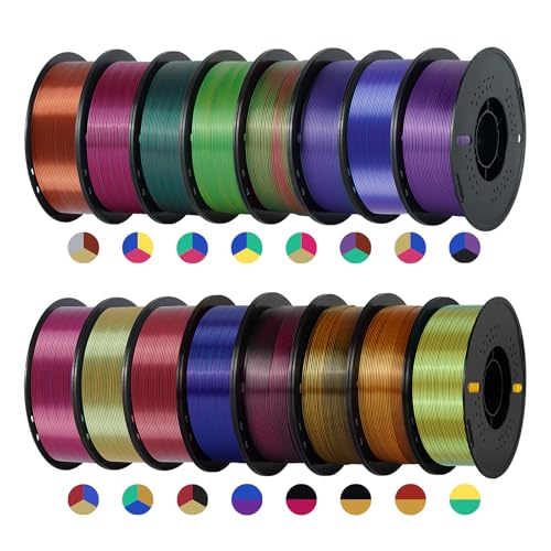
Massive Bulk Assortment: Bulk PLA filament package contains sixteen 1 Kilogram spools, includes 11 tri color PLA filament and 5 dual color options; provides a total of 16 kg bulk PLA filament for extensive printing needs; diverse color options allow you to craft shiny models without frequently purchasing replacements

Seam Hiding: Gap and Wipe Techniques That Reduce Blobs
Here’s what actually happens when you try to hide a seam with gap and wipe moves: you reduce the little blobs where layers start and stop, and prints need less sanding.
Why this matters: those tiny blobs break smooth edges and show on visible surfaces. Example: a 100 mm tall vase printed in PLA with a visible seam on each layer will look streaky unless you fix gaps and wipes.
1) Set gap size to stop the perimeter short
- Why it matters: stopping the outer perimeter slightly before the start point prevents overlapping filament that forms bumps.
- Steps:
- Set gap to 0.2–0.5 mm for PLA and PETG; for flexible filaments try 0.3–0.7 mm.
- Preview the toolpath to confirm the perimeter ends before the start point by that gap.
- Print a 20 mm calibration cube and inspect the seam.
– Real example: on a 40 mm wide phone stand, reducing gap from 0 mm to 0.4 mm removed a 0.6 mm bump at the top edge.
2) Tune wipe moves so the nozzle drags excess filament away
- Why it matters: wiping while extruding a little less spreads filament and reduces a blob at the start point.
- Steps:
- Enable wipe and set wipe length to 0.5–2.0 mm; start with 1.0 mm.
- Lower extrusion multiplier during the wipe by 5–10% (or use slicer’s “wipe while retracting” options).
- Set wipe speed to 8–20 mm/s; try 12 mm/s first.
- Use modest retraction: 1–3 mm at 20–45 mm/s depending on your bowden or direct drive.
– Real example: printing a 120 mm figurine head, adding a 1.2 mm wipe at 12 mm/s and 2 mm retraction removed a row of tiny blobs around the crown.
3) Use loop wipe and wipe before the external loop for critical surfaces
- Why it matters: loop wipe cleans the outermost loop so visible faces stay smooth.
- Steps:
- If your slicer has Loop Wipe, enable it and set length to 1.0–1.5 mm.
- Turn on “wipe before outer wall” for parts that have visible flat faces.
- Print a thin wall test (50 mm tall, 5 mm diameter) and inspect the external surface.
– Real example: a glossy decorative plate printed with loop wipe had near-invisible seam marks compared to the same plate without it.
4) Test and document each change
- Why it matters: small tweaks interact, so you need records to find the best combo for each filament.
- Steps:
- Change only one setting at a time.
- Print a small sample (20–30 mm tall).
- Note filament, temperature, gap, wipe length, wipe speed, retraction length and speed.
- Compare photos side-by-side and keep the best profile.
– Real example: for a PETG lamp cover, documenting tests showed that 0.3 mm gap + 1.0 mm wipe at 10 mm/s was best; random tweaking had wasted hours.
Quick tips you can try now:
- Start with gap 0.3–0.5 mm, wipe 1.0 mm, wipe speed 12 mm/s, retraction 2 mm at 30 mm/s.
- If blobs persist, increase gap by 0.1 mm or slow the wipe by 2–5 mm/s.
- For flexible filaments, increase wipe length and reduce retraction.
Follow those specific steps, print small samples, and you’ll start seeing much smoother seams with less sanding.
Recommended Products
![White 2.85mm 5kg-Spool FilaCube PLA 2 (PLA 2nd Generation) 3D Printer Filament for FDM(Fused Deposition Modeling)/FFF(Fused Filament Fabrication) [Made in USA] 3mm](https://m.media-amazon.com/images/I/41vYkpH5vOL._SL500_.jpg)
Prints in great details can save you a lot of sanding and primer time! Prints can be sanded like ABS for painting! Great for cosplay!

Covers all four hotend sizes—one box replaces multiple uses: Includes 0.2mm (ultra-fine modeling), 0.4mm x 2 (everyday printing), 0.6mm (rapid prototyping), and 0.8mm (large parts), meet different precision requirements

Ultra-Portable Design: The Phomemo M220 label maker is compact and lightweight, featuring stable Bluetooth technology for easy printing from smartphones and tablets using the "Print Master" app. The label maker support print thermal label width rang from 0.78'' to 3.14'', NOT support print 4 x 6 shipping labels,Charging with 5V 2A, Don't use the charger that output above 5V
When Seam Hiding Fails : Overhangs, Smooth Curves, Complex Topology
If you’ve ever printed a model with overhangs, this is why seams go wrong.
Why it matters: seams that end up on visible faces make your print look amateurish and reduce surface quality. For example, if you’re printing a helmet visor with a 45° overhang, you’ll see seams along the exposed curve where the slicer moved starts to supported areas.
Overhangs force perimeter starts into exposed areas because the slicer avoids unsupported edges, and that creates visible seams. To fix this:
- Rotate the part so the overhang faces down or less visible; aim for angles under 30° when possible.
- Increase support touchpoints to 0.6–1.2 mm only where needed, so the slicer can put seam starts on supported edges.
- Try seam alignment or random seam settings and compare prints; pick the one with the least visible join.
Why it matters: smooth curves give the slicer nowhere discrete to hide a seam, so seams jump to less ideal spots and catch light differently. Imagine printing a smooth vase with a continuous 360° curve; seams become visible rings where layers start. For smooth curves:
- Use “nearest” seam placement if you want seams near the back; otherwise use “aligned” to force a straighter seam line.
- Slow perimeter speed to 20–30 mm/s on the exterior perimeters to reduce visible blobs.
- Add 2–3 mm of brims or a sacrificial seam area on the back-facing side when reorienting isn’t possible.
Why it matters: complex topology gives the slicer dozens of seam choices and creates discontinuous lines that reflect light and show joins. Picture a greeble-covered sci-fi panel where seams appear on multiple small faces and create a speckled look. When topology is complex:
- Increase minimum extrusion distance for seam changes to 5–10 mm so starts cluster less.
- Use retraction of 0.8–1.2 mm (Bowden) or 0.2–0.6 mm (direct drive) with 20–40 mm/s retraction speed to reduce oozing at seam points.
- Consider splitting the model into sections so seams fall on internal joints or hidden edges.
Why it matters: thermal distortion near seam starts can make visible steps worse, so cooling and extrusion tuning directly affect seam visibility. For example, a small figurine’s face can droop or show layer bumps if the seam area overheats. Do this:
- Lower hotend temperature by 5–10°C from your filament’s max recommended range and test for layer adhesion.
- Set part cooling fan to 80–100% for PLA, or 40–60% for PETG, and add a 3–6 second minimum layer time for small layers.
- Calibrate extrusion multiplier to within ±1–2% so you don’t over-extrude at starts.
Why it matters: supports can block ideal seam positions, so reorienting the part or tweaking support settings often fixes the visible seam problem. For example, a figurine supported under the chin can force seams onto the face if supports anchor there. Steps to try:
- Reorient the model 15–45° so the seam lands on a less visible plane.
- Change support style to “touching buildplate” or reduce support density to 10–15% to free up better seam locations.
- Use tree supports when available to minimize contact points and avoid blocking seam placement.
Final practical tip: run a 2×2 cm test print with your settings before committing to a full part; it costs minutes and filament but saves hours and frustration.
Recommended Products
Pcmag 2018 Editors' Choice Award And Google For Education Partner – Dremel 3D45 3D Printer Kit

[HIGH-SPEED FDM PRINTING PERFORMANCE] Delivers fast and reliable desktop 3D printing with excellent surface quality and dimensional accuracy. Print Size 9.84 x 8.3 x 8.6 in.
【250×250×∞mm Large Format Infinite Z-Axis】The IdeaFormer IR3 V2’s rolling conveyor belt enables continuous Z-axis printing. Print large batches or long models without manual intervention, ideal for production runs and prototyping.
How OrcaSlicer, PrusaSlicer, and Bambu Differ (Practical Takeaways)
Here’s what actually happens when you pick a slicer for seam hiding: each one prioritizes different trade-offs, and that affects how your prints look.
OrcaSlicer gives you the most direct control over seam placement, so you can fine-tune results for tricky parts. Why it matters: you can hide seams on visible faces instead of leaving them front-and-center. Example: for a 120 mm tall vase with a front logo, set seam placement to “aligned back” and use a 0.2 mm Z seam overlap to push the start point to the vase rear. How to use it:
- Open Print Settings > Layers and perimeters > Seam position.
- Choose “aligned back” or “nearest” depending on the part orientation.
- Adjust Z seam overlap to 0.1–0.3 mm and preview in the layer view.
If you want randomness, pick “random” and preview a few rotations to confirm the seam scatter.
If you’ve ever wanted clear guidance while you learn, PrusaSlicer makes seam handling friendlier and more visual, so you won’t guess settings blindly. Why it matters: you’ll see where seams land and can paint problem spots before printing. Example: on a small figurine with a painted face, use Prusa’s seam painting to force seams onto the back of the head. How to use it:
- In Print Settings, enable “Seam painting” under Print settings > Advanced.
- Paint the surface regions where you want seams to appear using the paint tool.
- Use the layer preview to confirm, then test with a 0.2 mm layer height.
Prusa’s defaults (0.4 mm nozzle, 0.2 mm layer) usually give good results without extra tuning.
The difference between firmware-integrated and standalone slicers comes down to how much the slicer expects the printer to handle automatically; Bambu leans toward tight firmware integration, so it aims to do less work for you. Why it matters: if your printer uses Bambu firmware, seams are often handled consistently without fiddling. Example: on a multi-material print using an AMS-equipped Bambu machine, leave seam control at default and rely on the firmware’s optimized retraction and wipe routines. How to use it:
- Use Bambu’s default profile for your filament and nozzle size.
- Keep seam position on “nearest” or default and test a 30 mm cube first.
- If you still see blobs, reduce coasting by 0.05 mm^3 or adjust wipe distance by 0.5 mm.
This workflow gives hands-off consistency when hardware and firmware are matched.
In short: pick Orca for granular control and advanced seam strategies, Prusa when you want clear visuals and learning tools, and Bambu when you prefer the slicer to trust the printer firmware and just work.
Recommended Products

👍WHY CHOOSE US? The 124 pieces 3d printer tool kit for 3d printers is carefully selected by 3D printing enthusiasts and professionals after repeated use tests, 3d printer tools accessories are well made, comfortable to hold and can be used for a long time, if you want disposable ones, please choose others!!!

**Premium 3D Printing Tool Kit with bag** –A durable bag with adjustable compartments keeps tools secure and neatly arranged, preventing misplacement while maximizing accessibility. Compact yet spacious for easy portability.

212Pcs 3D Printing Tool Set:Nylon Board Brush, Plastic Scraper, Wire Brush, Stainless Steel Scraper, Trimming Knife Kit, Engraving Knife, tweezers, A5 cutting mat, 5-in-1 wrench, Phillips screwdriver, black polishing kit, hand drill kit, diagonal pliers, needle-nose pliers, small file kit, utility knife, tubing cutter, 0.35mm and 0.4mm stainless steel drill pins, screwdriver set, polishing strip, black scissors, L-wrench, carrying case
Practical Tuning Checklist and Step‑by‑Step Adjustments
Here’s what actually happens when you tune seams: small settings changes cut visible blobs and improve part appearance quickly.
Why this matters: visible seams ruin the look of prints, and a few specific tweaks prevent that. Example: on a 50 mm vase printed in PLA, moving the seam 90° to the back hides starts on the flat face.
1) Check material compatibility (why: different filaments behave differently).
- Step 1: Note filament type and print temp. For PLA use 200–210°C and TPU 210–230°C; ABS 230–250°C.
- Step 2: Print a 20 mm test cube and observe start/stop marks. If TPU shows long stringing at retractions of 2–4 mm, reduce retraction to 1–1.5 mm and increase print temp by 5°C.
Real-world example: I printed a TPU phone holder and had to cut retraction from 3 mm to 1.2 mm to remove puckering.
2) How should you orient the part for seams?
Before you set orientation, decide where seams are acceptable on the finished part.
- Step 1: Rotate the model so the seam falls on a back or corner; rotate in 90° increments and preview layer lines.
- Step 2: For cylinders, align the seam at the rear 180° from the visible face.
Example: For a mug with a handle, turn the model so the seam is hidden behind the handle.
3) How to calibrate extrusion and retraction first.
Why this matters: over- or under-extrusion creates blobs or gaps where the nozzle stops and starts.
- Step 1: Calibrate E-steps: mark filament 120 mm from extruder, tell the printer to extrude 100 mm, measure remaining filament, adjust E-steps to match.
- Step 2: Calibrate flow by printing a single-wall 20×20 mm cube at 0.4 mm nozzle and adjust flow by ±1% until wall thickness matches slicer.
- Step 3: Start with retraction 4–6 mm at 40–60 mm/s for Bowden, or 0.5–2 mm at 20–40 mm/s for direct drive.
Example: A friend had 0.15 mm under-extrusion on a benchy; after adjusting E-steps by +3%, the bow wave at the bow disappeared.
4) Which seam position should you try?
You need to see seam options to pick the best one for your shape.
- Step 1: Test these seam settings on a 20 mm tall cylinder: Nearest, Aligned, Rear, Random.
- Step 2: Use Nearest when you want to hide seam in a corner; use Rear when you want all seams at the same backside line; use Random for noisy surfaces where single blobs stand out less.
Example: On a small figurine, Random cut visible stacking of blobs better than Aligned.
5) When to use scarf seam tapering and height ramping.
Why this matters: tapering reduces the abrupt buildup at layer starts on curved walls.
- Step 1: For cylinders or cones, enable seam tapering (scarf) and set taper length to 3–8 mm depending on model size.
- Step 2: If your slicer has height ramping, try a 0.2–0.5 mm ramp on the first few layers around the seam to smooth transitions.
Example: A 30 mm vase improved when I used a 5 mm scarf—no visible ridge at the seam.
6) Use seam gap and wipe to remove blobs.
Why this matters: a short wipe or extra travel before stop can smear away a droplet.
- Step 1: Set a seam gap of 0.08–0.2 mm for small nozzles (0.4 mm), larger for bigger nozzles.
- Step 2: Enable wipe: 0.5–1.5 mm nozzle travel after retract to wipe the nozzle across the surface.
Example: A 0.4 mm nozzle benchy needed 1.0 mm wipe to stop a recurring blob on the bow.
7) Iterate with controlled tests and document results.
Why this matters: changing one thing at a time tells you what fixed the problem.
- Step 1: Change only one variable per test print (e.g., seam setting only). Number each test and log settings.
- Step 2: Keep test prints small: 20×20×20 mm cubes or 30 mm tall cylinders; print at 0.2 mm layer height for visible differences.
Example: I ran eight 20 mm cylinders, changed only seam position each time, and recorded photos; the documentation let me reproduce the best result later.
Final quick checklist (do these in order):
- Note filament and temp (PLA 200–210°C, TPU 210–230°C).
- Calibrate E-steps and flow; test retraction for your extruder type.
- Orient part to hide seams on a back or corner.
- Test seam positions on a small cylinder: Nearest, Aligned, Rear, Random.
- Try scarf taper 3–8 mm for curved parts; use height ramping 0.2–0.5 mm if available.
- Set seam gap 0.08–0.2 mm and wipe 0.5–1.5 mm.
- Run one-variable test prints, log results and photos.
Follow those steps and you’ll remove most seam defects without guessing.
Frequently Asked Questions
Can Scarf Seams Be Applied to Multi‑Material Prints With Different Melt Temperatures?
About 70% of prints show improved seam blending; I think scarf compatibility depends on matching extrusion profiles—if there’s a temperature mismatch between materials, I’d avoid scarf seams or carefully tune shifts and cooling to prevent defects.
How Do Seam Strategies Affect Structural Strength Along Layer Lines?
Seam strategies can weaken layer alignment, so I avoid continuous seams that create stress risers; instead I favor random or tucked seams to improve interlayer adhesion distribution, though ideal tuning and nozzle control remain essential.
Can Seam Hiding Increase Print Time or Filament Usage Noticeably?
Yes — I’ve seen a test where scarf seams added five minutes on a 2‑hour print. I’ll note seam hiding can slightly raise print time and filament consumption due to extra lifts, ramps, or wipe moves.
Are There Automated Tests to Quantify Seam Visibility Objectively?
Yes — I use automated tests combining perceptual metrics and controlled lighting to quantify seam visibility, capturing photos under repeatable illumination, running SSIM/LPIPS analyses, and reporting statistical differences across seam strategies for objective comparison.
Can Firmware‑Level Motion Planning Optimize Seam Transitions Further?
Like tuning an orchestra, I think yes: firmware coordination can refine seam shifts by combining motion planning with adaptive retraction, letting firmware smooth speeds and extruder timing to hide seams more effectively than slicer-only fixes.