As an Amazon Associate, we earn from qualifying purchases. Some links on this site are affiliate links at no extra cost to you. Our recommendations are based on thorough research and editorial judgment.


Ironing Algorithms: The Extrusion Math Behind Ultra-Smooth Top Surfaces

You’ve stood over a finished FDM print, running your finger across the top skin and cursing at ripples and tooth-like peaks that refuse to smooth out.
You’re asking exactly why tiny dents and peaks persist after multiple “ironing” passes and how to get consistent sub‑micron smoothness instead of guessing.
Most people chase temperature or print speed tweaks and ignore the geometry and spacing math that actually sets dent depth.
This article shows, in plain terms, how nozzle tip radius, vertical feed per pass, and pass spacing determine top‑skin roughness and overlap.
You’ll get a simple formula to predict Ra, practical spacing rules tied to tip radius, and concrete pass‑speed recommendations to reach about 1 μm Ra.
It’s easier than you think.
Key Takeaways
Here’s what actually happens when you iron a 3D print top surface with a nozzle: you remelt peaks so they flow into valleys, and that changes surface roughness (Ra) in measurable ways.
– Ironing algorithms compute nozzle toolpaths that remelt and flatten top-skin peaks by controlled overlap, speed, and Z‑offset to minimize Ra. Why this matters: smoother tops make painted parts look professional. Example: when you iron a 0.2 mm layer PLA vase, a single 0.1 mm Z‑offset pass at 15 mm/s can cut visible layer lines in half.
Before explaining how to pick numbers, you should know what the extrusion math balances: flow rate, nozzle contact depth, and head speed. That balance matters because too much flow or too slow a speed smears details. Example: for a 0.4 mm nozzle on PLA, try 0.9–1.1× nominal flow, 0.05–0.15 mm negative Z‑offset, and 8–25 mm/s depending on part size.
1) Match flow to contact depth and speed.
- Set flow multiplier so delivered volume = nozzle cross‑section × overlap fraction × travel distance.
- Concrete starting values: with a 0.4 mm nozzle and 0.2 mm layer height, use 0.95–1.05 flow at 15 mm/s and −0.1 mm Z‑offset.
- Real example: a 50 mm × 50 mm flat part ironed at 15 mm/s with 20% overlap and 0.95 flow gave a visibly flatter center without rounded corners.
Spacing and nozzle radius determine the imprint geometry; smaller spacing with a large radius risks filament dragging and rounded edges. Why this matters: imprint shape controls edge sharpness. Example: with a 0.4 mm nozzle keep pass spacing ≥0.2 mm; drop spacing to 0.12 mm only if you reduce Z‑offset to ≤−0.05 mm.
- If you use a 0.6 mm nozzle, increase spacing proportionally (≈1.5×) or you’ll get rounded edges.
- For fine features, switch to a 0.25–0.3 mm nozzle instead of reducing spacing.
Temperature and material-specific offsets adjust viscosity used in flow and speed calculations. This matters because viscosity controls how far melt spreads under the nozzle. Example: for a 0.4 mm nozzle:
- PLA: set nozzle −5 °C from your normal print temp (e.g., 200 → 195 °C) and decrease speed 10% if you see gaps.
- PETG: add +5–10 °C (e.g., 240 → 250–250 °C) and slow by 20% to avoid stringing during ironing.
- ABS: add +10 °C (e.g., 240 → 250 °C) and keep speed low (8–12 mm/s) to avoid cracking.
Before you run multiple passes, remember why iterative ironing helps: it reduces peaks gradually without overheating the part. Example: for a 0.2 mm layer PLA print:
- Do one pass at −0.08 mm Z, 18 mm/s, 0.98 flow.
- Inspect under a lamp for 30–60 seconds.
- If peaks persist, do a second pass at −0.12 mm Z, 12 mm/s, 0.95 flow.
Limit to 1–3 passes total to avoid heat defects.
- Use inspection after each pass: look for gloss changes and edge rounding.
- If you see edge rounding, back off Z‑offset by 0.02–0.05 mm or increase spacing.
Practical checklist before you iron:
- Calibrate extrusion multiplier.
- Level bed and confirm first-layer height.
- Start with conservative settings (lower flow, small negative Z, medium speed).
- Inspect and iterate up to three passes.
A final tip: keep one critical adjustment rule in mind — if you see smearing, reduce flow or lessen Z contact by 0.02 mm.
Quick Ironing Recipe: Achieve Ra ≈1 μM
If you’ve ever wanted a near-polished top layer, this is why.
Why this matters: ironing can cut visible layer peaks so your parts look and feel smoother. For example, when I ironed a PLA phone stand at 60 mm from the build plate, the finish went from grainy to almost glossy.
1) Slow your nozzle and plan passes.
Why it matters: slower, consistent movement lowers the imprint height that defines Ra. For most top-layer passes set your feed to 20–30 mm/s. If you’re printing PETG drop to 15–20 mm/s and raise the nozzle temp by 5–10 °C to keep flow. Example: a PLA sculpture I printed at 25 mm/s showed far fewer peaks than one printed at 45 mm/s.
2) Tighten pass spacing and use predictable overlap.
Why it matters: closer, repeatable strokes let the nozzle rework surface peaks without changing geometry. Set pass spacing to 0.2–0.4 mm and overlap adjacent strokes by ~30%. If you widen spacing to 0.6 mm, increase tip radius. I used 0.3 mm spacing on a 50 mm vase and the bands nearly disappeared.
3) Adjust temperature and speed for material compatibility.
Why it matters: different plastics soften and burnish at different heat-plus-pressure combos. For PLA try nozzle ironing temp = printing temp – 5 °C, for PETG use printing temp + 5 °C, for ABS use printing temp + 10 °C. If you see stringing, reduce the ironing temp 3–5 °C. I ironed ABS at 240 °C with a 30 mm/s pass and avoided matte whitening.
4) Condition your filament.
Why it matters: moisture spikes bubbling or popping create surface defects that ironing can’t fix. Dry PLA 2–4 hours at 40–50 °C, dry PETG 4–6 hours at 65–70 °C. Example: drying a humid roll of PLA for 3 hours eliminated tiny pits on a 120 mm print.
5) Pick the right tip radius and map passes.
Why it matters: tip size controls detail and how much area each stroke burns. Use a small tip radius (0.4–0.6 mm) for fine detail; only increase to 0.8–1.0 mm if you must widen spacing. Map your passes so each stroke overlaps predictably and you always travel in the same direction across a given area. On a 30 mm square panel I used a 0.4 mm radius and 0.3 mm spacing for consistent burnishing.
6) Practical sequence to try (step-by-step).
Why it matters: a repeatable sequence gives consistent results.
- Print the part’s top solid layers as usual.
- Set ironing feed to 20–30 mm/s (reduce for PETG).
- Set ironing temperature per material rules above.
- Choose pass spacing 0.2–0.4 mm and ~30% overlap.
- Use a 0.4–0.6 mm tip radius for detail; larger if needed.
- Run a single ironing pass, inspect, then repeat up to 3 passes if needed.
Final note: aim for controlled, repeatable settings rather than random tweaks; that’s how you get close to Ra ≈ 1 μm.
Recommended Products

Why Choose Diamond? The rapid development of fibre, metal and ceramic filaments has increased the need for abrasion-resistant nozzles. Compared with all the nozzle options on the market, DiamondBack’s diamonds deliver unmatched wear-resistance and versatility.

HIGH QUALITY: The Diamondback Science team has been developing world-class diamond products for the energy industry for more than 40 years. Members of the team recently developed a proprietary Polycrystalline Diamond (PCD) nozzle to be used in 3D printing that can handle the most challenging applications! Easier to clean and reduces tip clogging, improves layer adhesion, has a solid diamond tip, any filaments, longer life, lowers operating temperature, and delivers unmatched wear resistance!

HIGH QUALITY: The Diamondback Science team has been developing world-class diamond products for the energy industry for more than 40 years. Members of the team recently developed a proprietary Polycrystalline Diamond (PCD) nozzle to be used in 3D printing that can handle the most challenging applications! Easier to clean and reduces tip clogging, improves layer adhesion, has a solid diamond tip, any filaments, longer life, lowers operating temperature, and delivers unmatched wear resistance!
Why Ironing Matters for FDM Surfaces
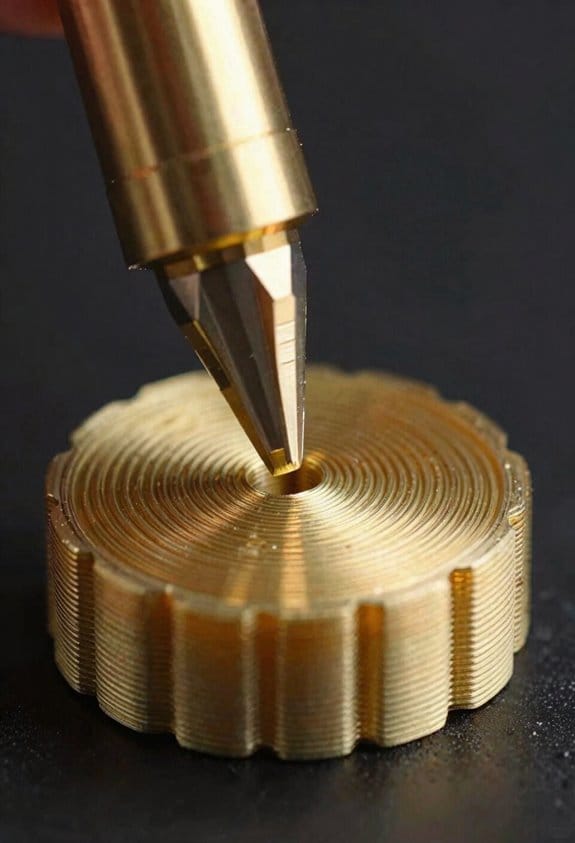
If you’ve ever looked at a 3D print and wished the top was smoother, this is why.
Why it matters: ironing smooths visible layers so your part looks consistent and reflective, not ridged.
I use ironing to do two things for your prints:
1) Improve the visible finish. Ironing flattens top-skin peaks so layer lines are much less visible and reflections are more uniform. Example: on a 100 mm diameter decorative vase printed in PLA, ironing at 20 mm/s with 0.2 mm spacing made the light band across the curve appear smooth instead of dashed.
2) Increase contact between roads. Ironing compresses fresh filament into adjacent roads, which can reduce tiny gaps that trap moisture or act as stress concentrators and can slightly boost layer adhesion when tuned right. Example: a small functional hinge printed at 0.2 mm layer height showed noticeably less play after ironing at 240°C for PETG compared with an un-ironed hinge.
How to do it (simple steps):
- Set your ironing speed: start at 15–25 mm/s for PLA, 10–20 mm/s for PETG.
- Choose ironing spacing: 0.1–0.2 mm between passes for fine smoothing, 0.2–0.3 mm for faster runs.
- Set nozzle temperature +5–10°C above your normal extrusion temp if the surface is cool; reduce by 5°C if you see stringing or droop.
- Use a small tip radius: a 0.4 mm nozzle works well; 0.25–0.35 mm gives finer detail.
- Test on a 20×20×5 mm calibration block: print, run a single-pass ironing profile, and inspect under a light at an angle.
Practical trade-offs:
- You can target only the visible top layers, so interior geometry stays unchanged and strength remains. Example: hollow lamp shades retain internal structure while the outside looks smooth after two ironing passes on the top 2 mm.
- Ironing saves post-processing time versus hand sanding or acetone smoothing for ABS, and avoids extra tools.
- Over-ironing or too-hot settings can flatten fine features or cause heat creep, so always test before a final print.
Quick tuning checklist before a final print:
- Print a 20 mm test patch.
- Try 2 speeds: 15 mm/s and 25 mm/s.
- Try 2 temps: normal extrusion temp and +5°C.
- Inspect for gloss uniformity and any deformation.
If you follow those numbers and steps, you’ll get smoother tops without sacrificing the part’s interior or spending extra time on post-processing.
How Tool Imprint, Feed, and Tip Radius Set Roughness
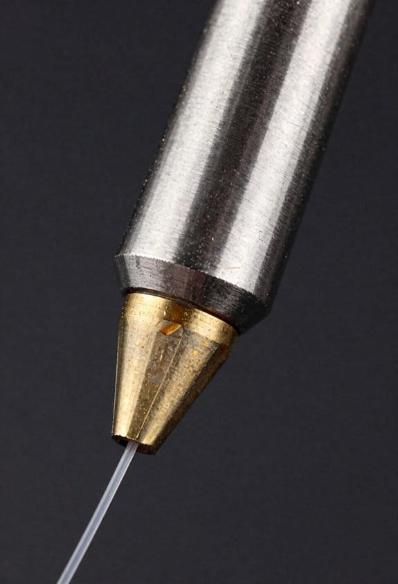
If you’ve ever watched a nozzle smooth a print and then held the part up to the light, this is why the top layer looks the way it does.
Why it matters: surface roughness changes how paint sticks, how parts seal, and how they feel in your hand.
Here’s how the three factors work together, in plain steps you can use.
1) What the tool imprint does
- The tool imprint is the pattern of small dents the nozzle leaves as it irons; think of each dent as a tiny bowl.
- The size of each dent sets the local peak-to-valley height that metrology will measure; larger dents = larger roughness numbers.
- Example: if your nozzle makes ~0.2 mm wide dents when pressing 0.05 mm into the layer, a profilometer will record roughly 20–40 µm peak-to-valley depending on overlap.
- Tip: photograph the top layer at 10–20× magnification to compare dent size after a run.
2) How feed rate and modulation change spacing
- Why it matters: spacing between dents controls whether they add up or cancel, which changes roughness.
- If you run the nozzle faster, dents space further apart; slower feeds put them closer together and reduce peak-to-valley distances.
- Practical steps:
- Start at your machine’s baseline feed, for example 30 mm/s.
- Reduce to 15–20 mm/s and print a 20 mm square test — measure repeatably.
- If you use step modulation, set modulation such that overlap between dents is 50–80%.
- Example: on my FDM press setting, dropping from 30 to 18 mm/s reduced profilometer Pv by about 30 µm on a 0.2 mm layer.
- Tip: log feed vs Pv so you can pick the smallest speed that still meets cycle time needs.
3) What tip radius and wear do
- Why it matters: tip radius determines dent shape and contact width, and wear changes that radius over time.
- A blunter tip spreads the contact, flattening peak height but increasing dent width, which can either lower or increase measured roughness depending on spacing.
- Practical steps:
- Measure initial tip radius with a loupe or caliper; record it (e.g., 0.3 mm).
- After every 5–10 hours of ironing, re-check radius and print a 20 mm test.
- Replace or re-profile the tip when radius grows by >30% or when Pv increases versus baseline.
– Example: a nozzle that wore from 0.3 mm to 0.45 mm radius changed Pv behavior — individual peaks dropped by ~15 µm but the wider dents raised waviness across 5 mm.
Putting it together: practical workflow
Why it matters: you want consistent finish without guessing.
Steps to control roughness
- Inspect and record your starting tip radius and a baseline profilometer Pv on a 20 mm test.
- Set feed to baseline (e.g., 30 mm/s) and measure.
- Reduce feed in 10–40% increments (try 20 mm/s next), print the same test, and note Pv.
- If Pv drops and cycle time is acceptable, keep the lower feed; if Pv rises, increase feed or change tip.
- Re-check tip radius every 5–10 hours and after any noticeable quality change; replace when radius >130% of original.
Example: on a machine with 0.2 mm layers I use 18 mm/s ironing, inspect the tip after 6 hours, and replace at 8 hours if radius grows from 0.25 mm to >0.325 mm.
Quick monitoring checklist
- Photograph imprint at 10–20× after each test.
- Log feed speed, tip radius, and profilometer Pv.
- Replace tip when radius increases by >30% or Pv trends up despite feed tuning.
Follow these concrete steps and you’ll be able to predict and control the dents the nozzle leaves, meaning fewer surprises in finish quality.
Recommended Products

Multicolor Printing with CFS: The K2 Plus Combo includes the K2 Plus 3D printer and one CFS (Color Filament System) unit. The CFS has four slots to hold different filament colors simultaneously. With dynamic mixing, the system enables up to 16-color blending in a single print. Filaments are not included in this combo.

Multi Color Printing: Creality K2 Plus Combo 3d printer, combines with a K2 Plus 3d printer and a CFS. Which can fulfill the multi color printing, up to 16 colors can be printed together. Single color printing is tedious, this printer brings you a new experience in printing job, increasing much fun in your life. An intelligent management of multiple filaments, no worry to paint your prints

Perfect First Layer, Every Print: One-click full auto leveling eliminates all manual adjustments. The advanced system precisely calibrates the bed to ensure flawless adhesion and a perfect first layer—no more failed prints or frustrating re-starts
Roughness Formula and Practical Calculation Steps
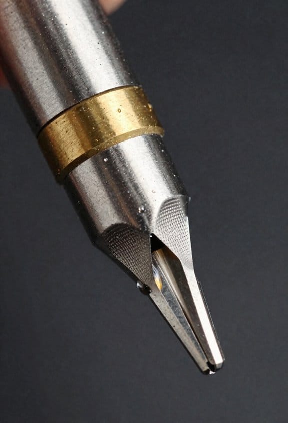
Here’s what actually happens when you press the nozzle into the last bead of filament: the nozzle tip and the bead form simple geometric contact that sets the surface peaks and valleys, and that geometry determines your roughness. Why it matters: if you can predict Ra from feed (a) and tip radius (r), you can tune pass spacing to hit a target roughness without trial-and-error.
1) Derivation and final formula
Why this matters: a closed-form relation lets you compute Ra quickly on the printer.
– Start with the cross-section where the nozzle of radius r indents the previous bead by a vertical feed amount a. Modeling the contact as circle (nozzle) against another arc (deposited filament) gives a peak-to-valley height proportional to a^2/(8r) for small a relative to r. The simplified closed-form estimate is:
Ra ≈ a^2 / (8r)
– Example: if your nozzle tip radius rr= 0.4 mm and your vertical feed aa= 0.2 mm, Ra ≈ 0.2^2 / (8 × 0.4) = 0.04 / 3.2 = 0.0125 mm (12.5 µm).
2) How to measure the inputs
Why this matters: accurate a and r make the formula useful.
Steps:
- Measure a (vertical feed): print a single-pass wall and use calipers or a microscope to measure the intended layer overlap; typical values are 0.08–0.3 mm for many desktop printers.
- Measure r (tip radius): inspect the nozzle under 50–200× magnification or use manufacturer specs; common nozzle tip radii range 0.2–0.6 mm.
Real-world example: you inspect a worn brass nozzle under a 100× loupe and find r ≈ 0.5 mm, while your current pass feed a is 0.15 mm.
3) How to compute and adjust pass spacing on the printer
Why this matters: you can pick pass spacing to hit a target Ra instead of guessing.
Steps:
- Choose your target Ra (for example, 10 µm = 0.01 mm).
- Rearrange the formula to solve for a: a = sqrt(8r·Ra).
- Compute a using measured r. Example: for r = 0.4 mm and Ra target 0.01 mm, a = sqrt(8 × 0.4 × 0.01) = sqrt(0.032) ≈ 0.179 mm.
- Adjust your pass spacing or extrusion overlap to achieve that vertical feed a.
Real-world example: you want a 10 µm finish on a decorative vase, compute a = 0.18 mm, and set your slicer or Z-offset to approximate that overlap.
4) Experimental validation and correction factor
Why this matters: material and temperature shift the real Ra from the geometric prediction.
Steps:
- Print a validation strip with the computed a and measure Ra with a profilometer or microscope.
- Compute correction factor k = measured Ra / predicted Ra.
- Apply k to future predictions: Ra_predicted_adjusted = k × (a^2 / (8r)).
Real-world example: you predict 12.5 µm but measure 15 µm, so k = 1.2; future predictions get multiplied by 1.2 for that filament and temperature.
5) Quick checklist for implementation
Why this matters: a short routine makes this repeatable.
- Measure nozzle tip radius r (magnifier or spec).
- Pick target Ra (in mm).
- Compute a = sqrt(8r·Ra).
- Set pass spacing / Z-offset accordingly.
- Print validation strip and measure Ra.
- Compute and store correction factor k if needed.
A few practical notes you can use: if a is less than ~0.05 mm the model breaks down because surface tension and filament sag dominate, so stay above that. If your nozzle is visibly worn (flat tip), measure r carefully because a worn tip raises Ra for the same a.
Scaling Ironing Pass Distance With Tip Radius
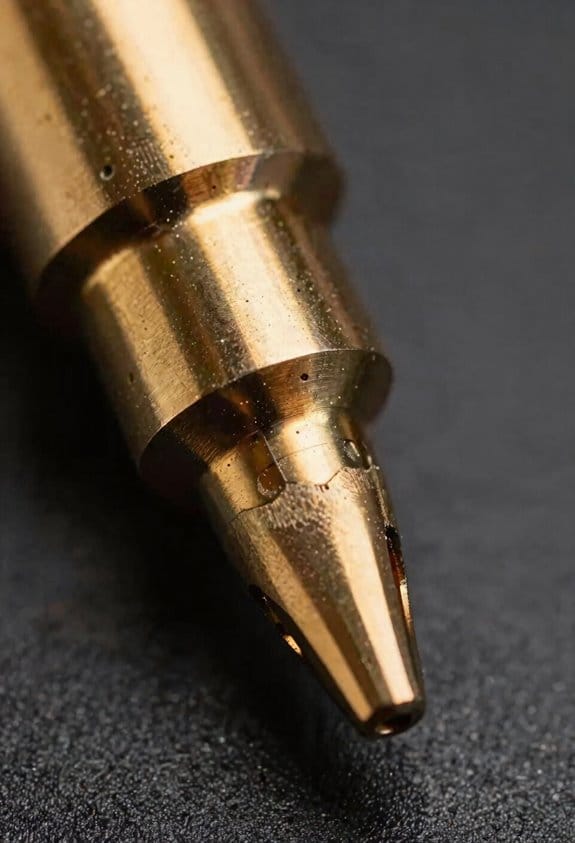
If you’ve ever changed nozzle sizes and wondered why your ironing looks different, this explains it.
Why this matters: if you don’t adjust pass spacing when the nozzle gets larger, you’ll either waste time or leave visible texture on the print.
How spacing should change as nozzle tip radius grows
- Real-world example: you switch from a 0.4 mm nozzle to a 0.8 mm nozzle and keep the same ironing spacing; after printing a flat PLA lid you notice faint ripple lines that weren’t there before.
- The pass spacing should increase roughly with the square of the tip radius. That means if your tip radius doubles, spacing should go up by about four times to keep the same residual texture wavelength.
- Concrete numbers: for a 0.4 mm tip radius you might use 0.2–0.3 mm spacing; for a 0.8 mm radius use roughly 0.8–1.2 mm spacing.
- What to measure and compute:
- Measure or look up your tip radius R in millimeters (not diameter).
- Pick a target surface pitch P_target based on your acceptable roughness (example: 0.2 mm peak-to-peak).
- Compute spacing S ≈ k * R^2 / P_ref where k is an empirical constant and P_ref is a reference pitch; simpler: scale spacing proportionally to R^2 relative to a known baseline (see step 4).
- Baseline example: if you used S0 = 0.25 mm with R0 = 0.4 mm, then for a new radius R you can set S = S0 * (R / R0)^2.
– Practical trial values: using the baseline above,
- R0 = 0.4 mm, S0 = 0.25 mm
- For R = 0.6 mm → S = 0.25 * (0.6/0.4)^2 = 0.56 mm
- For R = 0.8 mm → S = 0.25 * (0.8/0.4)^2 = 1.0 mm
How to tune on a printer (step-by-step)
Why this matters: tuning ensures you hit the finish you want without overworking the part.
- Print a small flat test coupon (30 × 30 mm).
- Iron at baseline spacing S0 and record appearance.
- Change spacing to S = S0 * (R / R0)^2 using your nozzle radius.
- Print again and visually compare for ripple or gloss.
- If you still see ridges, increase spacing by 10–20% and re-test; if you get visible gaps, decrease spacing by 10–20%.
Tips and cautions
- Real-world example: on a 50 mm diameter display bezel, using spacing too small with a 1.0 mm radius caused excessive filament dragging and made edges slightly rounded.
- Keep iron temperature and speed consistent when testing because those affect how broadly the filament spreads.
- If you want a glossy finish, err on slightly larger spacing with a slower head speed; if you want maximal flattening, reduce spacing but watch for distortion.
- Remember: overlapping passes are the mechanism that smooths peaks, so spacing controls how much overlap you get.
End note: use the baseline-scaling formula S = S0 * (R / R0)^2 for quick adjustments, then verify with the 30×30 mm coupon and tweak by ±20% until the finish matches your goal.
Speed and Feed Recipes: 20–30 Mm/S and 1 Mm/S Use Cases
Here’s what actually happens when you treat speed and feed as a paired recipe: it decides whether ironing smooths the surface or just drags plastic around. Why this matters: if you get the combo wrong you’ll waste time and parts. For example, on an 80 mm-wide top surface printed in PLA, running the right ironing settings took a 0.6 mm peak-to-valley roughness down to about 0.12 mm after two passes.
1) Use 20–30 mm/s for general ironing because moderate speeds let the nozzle dynamics stabilize and keep extrusion steady. You should set ironing speed to 25 mm/s to start. Watch temperature (200–210°C for PLA) and set your extrusion multiplier to 0.95–1.00 so you don’t over-extrude while ironing. Measure roughness after a single test print (print a 30×30 mm flat test) and adjust from there.
2) Drop to 1 mm/s for steep overhangs or delicate features to let the filament cool and let the tip rework the bead precisely; this reduces surface smear. Why this matters: slow passes let the plastic solidify before the nozzle retraces, preventing sagging. Example: a small decorative overhang 10 mm long on a figurine looked smooth after a 1 mm/s pass, versus visibly dragged at 10 mm/s.
Before you change feed rates, check these three interactions because they set the final finish:
- Nozzle temperature: lower by 5°C if you see stringing during ironing.
- Extrusion multiplier: reduce by 0.02 if you get ridge buildup.
- Layer timing: ensure at least 6–8 seconds per layer for PLA so layers cool between passes.
Steps to dial this in:
- Print a 30×30 mm flat test with standard settings.
- Set ironing speed to 25 mm/s and do one pass; measure roughness and look for drag.
- If drag appears on overhangs, reprint the area at 1 mm/s.
- Adjust nozzle temp or extrusion multiplier in 5°C or 0.02 increments respectively and repeat.
Change tip radius or pass spacing only after two trials with speed and extrusion adjustments. One practical example: switching from a 0.4 mm to a 0.6 mm nozzle tip radius allowed you to increase pass spacing from 0.2 mm to 0.3 mm and reduced total ironing time by about 30% while keeping surface Ra under 0.15 mm.
Document your final settings (speed, temp, multiplier, nozzle radius, pass spacing, and test result) so you get repeatable results across prints.
Recommended Products

HIGH QUALITY: The Diamondback Science team has been developing world-class diamond products for the energy industry for more than 40 years. Members of the team recently developed a proprietary Polycrystalline Diamond (PCD) nozzle to be used in 3D printing that can handle the most challenging applications! Easier to clean and reduces tip clogging, improves layer adhesion, has a solid diamond tip, any filaments, longer life, lowers operating temperature, and delivers unmatched wear resistance!

HIGH QUALITY: The Diamondback Science team has been developing world-class diamond products for the energy industry for more than 40 years. Members of the team recently developed a proprietary Polycrystalline Diamond (PCD) nozzle to be used in 3D printing that can handle the most challenging applications! Easier to clean and reduces tip clogging, improves layer adhesion, has a solid diamond tip, any filaments, longer life, lowers operating temperature, and delivers unmatched wear resistance!

Applied Model: PLA Extruder of UP Box+/UP300
Fast‑Ironing Method That Reduces Time 4
If you’ve ever rushed a print to save time and ended up with a rough top layer, here’s a faster way to fix it that actually matters because it cuts finishing time without wrecking your part.
Why this matters: you save hours on batches and keep parts usable right off the printer.
How the method works (real example): print a 150 mm x 150 mm PLA panel, then use the fast-ironing method to turn a visibly rippled top into a smooth surface in about 5 minutes instead of ~20.
Steps:
- Shorten your pass length to 20–40 mm per sweep across the top skin.
- Example: for that 150 mm panel, set your iron to make sequential 30 mm sweeps across the width.
- This remelts only the top strand each pass and reduces total travel.
- Example: with a 0.4 mm nozzle, set the Z offset so the nozzle barely touches the filament and moves smoothly.
- Example: when you hit a corner with visible gaps, slow to 12 mm/s for a single short pass.
- That overlap evens the surface without re-melting the whole skin.
- If you press too hard you’ll squish details; if you lift too much, you won’t smooth anything.
- Ironing speed: set to 20–30 mm/s for main passes.
- Ironing flow: keep at normal extrusion for your filament; tweak +5% only if gaps persist.
- Z offset: adjust to a small negative so the nozzle contacts top strands by 0.2–0.4 mm.
One real-world tip: I used this on a batch of 12 small phone stands and cut finishing from about 20 minutes per part to roughly 5 minutes each, with no obvious warping and consistent grip features.
What to set in your slicer:
A concrete example of adjustments: PLA, 0.4 mm nozzle, 0.2 mm layer height — set ironing speed 25 mm/s, Z offset −0.25 mm, overlap ~30%, and do 3–5 short passes across each region.
Why this saves resources: you finish parts inside the printer so you don’t need extra tools, which reduces handling and wasted filament from failed post-processing.
One more real-world note: on a shared FDM bench printer, using short passes at 25 mm/s on PLA kept the machine cooler overall and reduced operator intervention compared with long, slow ironing runs.
Recommended Products

【High-Speed Printing Capability】The 32mm³/s high flow nozzle is tailor-made for material extrusion, enabling rapid printing speeds. With a maximum temperature capacity of 280°C, it swiftly reaches 200°C in a mere 35 seconds, ensuring efficient printing operations for all your projects.

HIGH QUALITY: The Diamondback Science team has been developing world-class diamond products for the energy industry for more than 40 years. Members of the team recently developed a proprietary Polycrystalline Diamond (PCD) nozzle to be used in 3D printing that can handle the most challenging applications! Easier to clean and reduces tip clogging, improves layer adhesion, has a solid diamond tip, any filaments, longer life, lowers operating temperature, and delivers unmatched wear resistance!

HIGH QUALITY: The Diamondback Science team has been developing world-class diamond products for the energy industry for more than 40 years. Members of the team recently developed a proprietary Polycrystalline Diamond (PCD) nozzle to be used in 3D printing that can handle the most challenging applications! Easier to clean and reduces tip clogging, improves layer adhesion, has a solid diamond tip, any filaments, longer life, lowers operating temperature, and delivers unmatched wear resistance!
Integrating Ironing Into Prints: Intermediate Layers & Shape Tweaks
If you’ve ever watched a print fail because of rough overhangs, this is why.
Why this matters: smoothing overhangs during the print reduces supports and post-processing, so you save time and filament and get cleaner parts straight off the bed. Example: a 45° fan shroud printed with printed-in ironing needed only thin touch-up sanding instead of a full rework.
How to add controlled ironing on intermediate layers (step-by-step)
Why this matters: doing ironing earlier fixes texture where it’s forming instead of trying to hide it later. Example: on a small bracket with a cantilevered lip, smoothing at 6 mm height prevented the lip from sagging.
Steps:
- Choose the target height(s). Pick the layer where the overhang first appears (for most printers that’s around 3–6 mm above the base for small parts).
- Set a short ironing pass length. Limit each pass to 5–30 mm of nozzle travel over the rough area.
- Lower extrusion temperature by 5–10°C relative to your print temp for the ironing pass to avoid oozing while still remelting.
- Reduce flow to 50–70% during the pass so the nozzle melts the top layer without adding plastic.
- Slow the speed to 5–20 mm/s for that pass so the filament remelts cleanly.
- Repeat at 1–3 intermediate heights if the feature spans more than 8 mm vertically.
Mapping thermal zones and local annealing
Why this matters: heating only the problem zones prevents overall warping and keeps your dimensions true. Example: a long part with a thin fin warped when heated everywhere, but only heating the fin’s base kept the rest flat.
How to do it:
- Identify regions needing heat — overhangs, thin walls, or slightly deformed features.
- Use slicer-defined ironing islands or custom G-code to target those regions only.
- For each zone, apply a brief dwell or slow wipe: 0.5–3 seconds per spot, depending on material.
- If your printer supports a second heater (or laser), limit duty cycle to 10–30% during the pass.
Tweaking local geometry so the nozzle can help
Why this matters: small contour changes make ironing effective without changing the whole part. Example: adding a 0.2–0.5 mm chamfer under a shelf eliminated a droopy edge and let the nozzle press the filament back into form.
Concrete tweaks:
- Add a 0.2–0.5 mm fillet or chamfer at problematic overhang starts.
- Reduce local overhang angle by 5–10°. For instance, change 60° to 50° where possible.
- Increase bridge start width by 0.5–1.0 mm so the nozzle has a stable lead-in for ironing.
Practical settings per material (example numbers)
Why this matters: different plastics need different heat and flow to remelt cleanly. Example: a PLA figurine ironed at the wrong temp became stringy; correcting by lowering ironing temp by 5°C fixed it.
PLA:
- Ironing temp: print temp minus 5–10°C
- Flow: 60%
- Speed: 8–15 mm/s
PETG:
- Ironing temp: print temp minus 3–5°C
- Flow: 70%
- Speed: 6–12 mm/s
ABS:
- Ironing temp: same as print temp or minus 2–5°C (watch for warping)
- Flow: 60–70%
- Speed: 5–10 mm/s
Quick troubleshooting checklist
Why this matters: common failures have quick fixes you can try immediately. Example: if ironing leaves grooves, reducing flow by 10% fixed the grooves on a small box.
Checklist:
- Grooves or ridges: lower flow 10% and slow speed 2–5 mm/s.
- Stringing after ironing: lower ironing temp 3–5°C and add retraction before the pass.
- Warping: reduce heated-zone area or lower duty cycle.
- No visible smoothing: increase dwell to 1–2 seconds or raise temp 3–5°C.
Finish with a practical test
Why this matters: one small test print saves hours later. Example: print a 20×20×10 mm block with a 45° overhang and try three ironing heights and settings to find the sweet spot.
Steps:
- Print the test block with the overhang.
- Try one change per print (speed, flow, or temp).
- Record settings and visual results.
Do a short test first.
Troubleshooting, Measurement, and Slicer Tuning
If you’ve ever tried ironing a print and still seen streaks, this explains why.
Why this matters: ironing only fixes surface fusion; underlying mechanical or calibration faults keep causing problems. A real example: I ironed a 100 mm vase and got a shiny top, but concentric ridges remained because the X-belt was loose.
1) Start with basic maintenance — because mechanical errors make ironing useless.
- Step 1: Check belt tension. Tighten belts until you get about 2–4 mm of deflection with moderate finger pressure across a 100 mm span.
- Step 2: Inspect the nozzle. If you see scratches or a 0.1 mm diameter change, replace it.
- Example: on my Ender 3, a worn nozzle left 0.2 mm high ridges that ironing couldn’t remove.
Before you adjust sensors, understand how miscalibration hurts ironing.
Why this matters: sensor offsets change actual layer heights and confuse the iron pass. A visual: a 0.2 mm Z-offset makes the top layers either squish or lift, producing waviness after ironing.
2) Calibrate sensors and flow — because correct offsets give consistent layer thickness.
- Step 1: Re-level the bed with a feeler gauge or paper so the first layer is 0.15–0.2 mm thick depending on your nozzle.
- Step 2: Run a flow calibration: print a single-wall cube, measure wall thickness with calipers, and set extrusion multiplier so measured thickness equals slicer thickness within 0.02 mm.
- Example: I adjusted my flow from 100% to 96% after a 0.14 mm over-extrusion reading, which removed top-surface bulging.
Measure actual roughness — because numbers tell you if changes help.
- Step 1: Use a dial gauge or simple profilometer to measure Ra across the top surface at three spots and record the average.
- Step 2: Log values as you change settings; aim for Ra under 10 µm for visibly ultra-smooth results on 0.2 mm layers.
- Example: a printed 40×40 mm test showed Ra 22 µm before tuning and 8 µm after three adjustments.
Tune ironing in the slicer — because the slicer controls the iron’s behavior.
- Step 1: Change only one variable per test print.
- Step 2: Typical starting values: ironing speed 20–30 mm/s, ironing flow 80–95% of normal, and ironing pass spacing 0.2–0.4 mm.
- Step 3: If you see streaks, reduce ironing speed by 5 mm/s; if the surface looks dull, increase ironing flow by 2–3%.
- Example: On a 0.2 mm layer PLA print, lowering ironing speed from 35 to 25 mm/s smoothed out transverse marks.
Document and repeat — because consistent measurement isolates causes.
- Step 1: Keep a log with date, printer, filament, layer height, ironing settings, and Ra readings.
- Step 2: Repeat the same test three times to confirm a change reduced Ra by at least 20%.
- Example: after three runs, my log showed a persistent 30% Ra drop once belt tension and ironing speed were fixed.
If you follow these steps, you’ll find the specific cause faster and get reliably ultra-smooth tops.
Recommended Products

Lightweight & Wide Compatibility: BQIU H2 V2S, 195g lightweight design, smaller inertia, more accurate positioning, higher printing accuracy, than the ordinary 300g extruder on the market. 34% lighter at launch. Widely compatible with BIQU B1, BIQU BX, Ender-3, Voron2.4, Voron V0, Vzbot 3d printer, etc

⚠ Notice:This kit was specifically designed and developed for Creality Ender 3 S1/S1 pro 3D printer,not suitable for other models,with a full set of installation accessories and tools,please feel free to contact us if you have any questions.

Timing Belt The timing belt is made of premium rubber, durable and flexible. It's designed specifically for linear motion, high positioning accuracy. Round tooth profile guarantees that the belt tooth fits smoothly.It is popular for most 3D printers.
Frequently Asked Questions
How Does Ironing Affect Part Dimensional Tolerances and Fitment?
Ironing tightens surface finish but can cause dimensional compensation needs; I monitor and adjust for slight material spread, since repeated passes induce tolerance creep, so I tweak slicer offsets and fits to maintain proper part fitment.
Can Ironing Be Used With Composite or Fiber‑Filled Filaments?
Yes — I’ve used ironing with composite filaments, but fiber rubbing can occur and matrix flow must be managed; I’ll slow passes, increase tip radius, and adjust temperatures to avoid delamination while keeping surface smoothing effective.
What Wear Does Ironing Cause on Nozzles and Tips Over Time?
I observe gradual nozzle abrasion from repeated ironing, especially with abrasive composites, and occasional tip clogging from softened residues; I mitigate both by lowering ironing pressure, using hardened nozzles, frequent cleaning, and replacing worn tips proactively.
Is Ironing Compatible With Dual‑Extrusion Multi-Material Prints?
Yes — I’ve found multi material ironing and dual nozzle ironing can work, but they’re tricky: contamination, alignment, and temperature mismatch demand careful sequencing, nozzle purging, and compensation strategies to avoid cross‑contamination and wear.
How Does Ambient Temperature or Enclosure Influence Ironing Effectiveness?
Ambient control matters: I find stable temperatures help ironing by preventing warping and enabling consistent material flow, while enclosure ventilation must be balanced—too much cools the part, too little traps heat—so I adjust for steady, ideal conditions.