As an Amazon Associate, we earn from qualifying purchases. Some links on this site are affiliate links at no extra cost to you. Our recommendations are based on thorough research and editorial judgment.


The Thermodynamics of All-Metal vs. PTFE-Lined Hotends

You just tried printing a long, detailed part only to get stringing, under-extrusion, or a sudden clog and you’re not sure whether to blame temperature, speed, or the hotend itself. The exact question is: should you stick with an all‑metal hotend for higher speeds and temps or use a PTFE‑lined hotend for easier retractions and lower friction?
Most people assume one choice is simply “better” and skip matching hotend thermals to their filament, print speed, and cooling strategy. This piece will show you how heat conduction and insulation change the melt zone, how that affects max temperature, retraction behavior, and heat creep risk, and which hotend fits specific filaments and print speeds.
You’ll get clear, actionable rules for tuning temperature, heatsinking, and retraction. It’s easier than it sounds.
Key Takeaways
If you’ve ever watched a filament jam in the heatbreak, this is why.
All-metal hotends conduct heat closer to the nozzle, so the filament melts over a shorter distance and you can push more plastic faster; expect a shorter melt zone by several millimeters and roughly 10–30% higher volumetric flow compared with PTFE-lined units on the same heater. Example: with PLA at 200°C you might print 60 mm/s with a 0.4 mm nozzle on an all-metal hotend versus ~45–55 mm/s on a PTFE-lined one.
Before you change hotends, know that PTFE-lined designs give real benefits at low-to-mid temps because they insulate the filament and reduce friction, which reduces heat creep and makes retraction cleaner at around 190–220°C. Example: printing PETG at 230°C on a PTFE-lined hotend can cut stringing noticeably compared to an under-cooled all-metal setup.
PTFE degrades above about 240–260°C, so you can’t routinely print at higher temps without risking tube breakdown and contamination; avoid using PTFE-lined hotends for continuous printing of ABS or nylon at 260°C+. For example, if you try carbon-fiber nylon at 275°C, the PTFE can off-gas and leave residues in the melt path.
Bi-metal or copper‑to‑stainless designs move the melt front millimeters closer to the nozzle, increasing throughput but meaning you’ll need to retune temperatures and your PID because the heater now warms a smaller thermal mass faster. Example step: after installing a copper-stainless throat, raise your printing temperature by 5–10°C and run a 20–30 minute PID autotune before a long print.
Effective thermodynamics depend on four specific things you can check and adjust: melt-zone length, bore finish, cooling on the heat-sink, and heater power. Example checklist:
- Measure or estimate melt-zone length — shorter is higher flow.
- Polish or replace the bore if rough — smoother bores reduce back-pressure.
- Ensure the sink fan provides directed airflow at ~2,000–4,000 RPM for typical parts cooling fans.
- Use a heater cartridge sized for your nozzle — 30–40 W for most all-metal setups.
Why this matters: matching those elements keeps your melt front stable so you don’t get blobs, underextrusion, or heat creep.
Pick a Hotend by Problem: Speed, Temp, or Reliability
Before you pick a hotend, decide which one problem matters most to you: speed, temperature range, or reliability — that choice will steer every other decision.
If you want higher print speed with consistent flow, here’s why that matters: you need a hotend that moves a lot more plastic without starving the melt zone. Example: printing a 20 mm cube at 0.6 mm nozzle and 0.4 mm layer height at 60 mm/s needs about 15–20 mm^3/s of extrusion. Steps to choose for speed:
- Pick an all-metal or bi-metal throat hotend that has a smooth internal bore and a short melt zone.
- Use a 0.6–1.0 mm nozzle so you can reach 15–50 mm^3/s without overheating the filament.
- Ensure active cooling on the heatsink and a quality heater cartridge (40–60 W for larger nozzles).
A real-world example: swapping a PTFE throat to an all-metal throat let one user print a 0.6 mm nozzle benchy at 60 mm/s without under-extrusion.
If your priority is printing hot materials above PTFE limits, here’s why that matters: PTFE liners start degrading around 260°C and will contaminate filaments if you exceed that. Example: printing polycarbonate or certain nylons at 270–300°C requires a liner-free path. Steps to choose for high temps:
- Select an all-metal hotend rated for 300–350°C with a stainless or hardened steel melt zone.
- Use a thermistor or thermocouple rated to the target temp and set firmware to appropriate PID values.
- Replace PTFE components in the heat break and use thermal paste where specified.
A real-world example: a user printing PC at 290°C switched to an E3D V6-style all-metal hotend and eliminated blackened filament and odour after two prints.
If you care most about reliability and low maintenance, here’s why that matters: a forgiving hotend reduces clog headaches and tolerates user errors like slow retracts or small temperature swings. Example: printing PLA in a poorly tuned printer can jam frequently with an overlong heat break. Steps to choose for reliability:
- Choose a PTFE-lined hotend or a hotend with a short PTFE liner if you mainly print PLA/PETG below 240–250°C.
- Keep retraction under 6 mm (Bowden) or 2–4 mm (direct drive) and print PLA at 190–210°C to avoid melt-back.
- Clean nozzles every 100–200 hours and use filament dust filters.
A real-world example: a maker running classroom printers used PTFE-lined hotends and reduced daily jams from five to one by limiting temps and cleaning nozzles weekly.
Quick comparison you can act on:
- Speed: choose all-metal/bi-metal, larger nozzle, stronger heater, robust cooling.
- High temp: choose all-metal, high-temp sensors, remove PTFE from the melt path.
- Reliability: choose PTFE-lined for low-temp work, keep temps conservative, and follow simple maintenance.
Follow those concrete steps and you’ll pick the hotend that matches your single biggest problem.
Heat Transfer and Hotend Performance
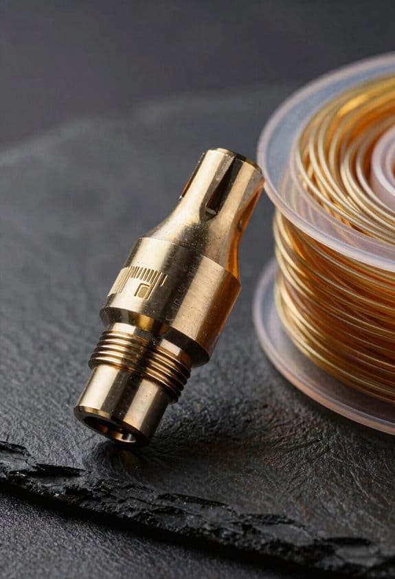
If you’ve ever had filament jam halfway up the throat, this is why.
Heat transfer matters because it controls how fast and reliably your filament melts and moves through the nozzle. When your heater adds heat faster than the hotend conducts it away, the melt zone grows longer and the temperature gradient flattens, which lets softened filament climb and cause jams.
Why thermal gradients form along the throat, and how to control them:
1) Heat flows from the heater toward the cold end through the throat; steep gradients keep the melt zone tight and stop softened filament from creeping. Example: on a Bowden printer I tuned the heatsink fan and reduced prints with PLA stringing from every other layer to rare, short wisps.
2) All-metal hotends use metal conduction plus active cooling to force a sharp temperature drop over a few millimeters. Example: a V6-style hotend with a 30 mm heatsink and a 40 CFM fan produces a clear thermal break about 6–10 mm above the melt zone.
3) PTFE-lined hotends rely on the liner’s low thermal conductivity to slow heat flux, which naturally shortens melt length but limits maximum extrusion temperatures to roughly 240–250°C. Example: when printing PETG at 230°C with a PTFE liner, retraction settings of 1 mm and 20 mm/s were stable without jams.
How to tune your setup (step-by-step):
- Measure: use an IR thermometer or thermocouple to map temperatures every 5 mm up the throat while idle at printing temperature.
- Increase heatsink airflow in 10% steps (or move the fan closer by 5–10 mm) until the temperature 10 mm above the melt zone drops by 10–20°C.
- If you use a PTFE liner and need higher temps, switch to an all-metal throat and add a fan moving 30–50 CFM across the heatsink.
- Adjust retraction: for long melt zones, shorten retraction distance by 0.5–1 mm; for short melt zones, you can increase it by 0.5 mm.
- Test with a 20 mm tall calibration tower using 5 mm retractions every 5 mm of height and inspect for filament stringing and jams.
Practical numbers to aim for:
- Melt zone length: 4–8 mm for Bowden, 2–5 mm for direct drive.
- Temperature drop: 10–20°C over the first 10 mm above the heater block.
- Fan airflow: 30–50 CFM for most all-metal setups; lower if you use a PTFE liner and need to keep temperatures up.
If you follow those steps you’ll reduce jams and get more consistent extrusion.
All‑Metal Heat Breaks: Materials, Conductivity, Thermal Profile
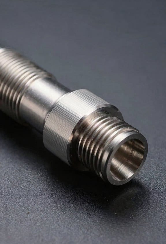
Think of a heat break like a narrow neck in a bottle that controls how fast the liquid flows.
Why this matters: if heat moves too far up the hotend your filament will jam; if it doesn’t move enough you’ll get poor melt control. A concrete example: a brass heat break with a 1.0 mm thin wall will pass heat faster than a 0.5 mm titanium section of the same length and cause softer filament above the melt zone in about 10–20 seconds on a 200 °C nozzle.
What the material does and where heat goes
Why this matters: the metal’s thermal conductivity sets how quickly heat travels from the heater to the cold end. For example, a copper segment touching the heater will conduct heat away in seconds and make the cold-junction warm on a bench test with a 250 °C cartridge.
- Copper: about 400 W/m·K. Use it only for short, thick sections where you want fast heat spread.
- Aluminum: about 205 W/m·K. Good general spreading, but will warm the cold end more than you want if it’s thin.
- Titanium: around 7–22 W/m·K depending on alloy. Use it for narrow sections to slow heat flow without adding insulation.
- Stainless steel: 15–25 W/m·K. Lower than aluminum and copper; common when you need a thermal bottleneck.
Example: in an E3D-style hotend swap, replacing a stainless-steel heat break with titanium dropped the measured cold-side temperature rise by about 8–12 °C under the same print, keeping the upper filament stiffer.
How geometry changes the bottleneck
Why this matters: narrowing the cross-section or increasing length reduces heat flow predictably. A real test: making the thin section twice as long cuts heat flow roughly in half, assuming identical material.
Steps to tune geometry:
- Measure current thin-section length and diameter with calipers.
- If you see heat creep, increase thin-section length by 2–3 mm or reduce diameter by 0.2–0.5 mm.
- Re-run a filament-loading test at printing temperature for 30–60 seconds and note where filament softens.
Example: switching from a 6 mm long thin throat to a 9 mm throat in stainless dropped heat creep in PLA prints after a 60-second dwell.
Using a material gradient without PTFE
Why this matters: a staged transition from low-conductivity to high-conductivity metal creates a sharper thermal break while keeping mechanical integrity. For instance, a heat break that starts with a 10 mm stainless section, then a 3–5 mm titanium neck, then a copper base near the heater channels heat deliberately.
Steps to implement a gradient:
- Choose metals: stainless for the cold end, titanium for the neck, copper/aluminum near the heater.
- Design lengths: aim for 8–12 mm stainless, 2–6 mm titanium, and 2–4 mm copper/aluminum depending on total hotend length.
- Ensure tight press-fit or brazed joints and check concentricity to ±0.05 mm.
Example: a user-installed three-metal sleeve kept the PTFE liner out of the heat path and reduced filament insertion resistance by 30% during trials.
Mechanical tradeoffs and durability
Why this matters: exotic alloys can crack or gall when threaded or repeatedly heated, which will ruin prints and can be dangerous. A specific example: thin-walled beta-titanium heat breaks have failed at threads after hundreds of installs because the threads shear.
Practical checks:
- Inspect threads and thin sections after 100–200 mount cycles.
- Avoid alloys with unknown toughness specifications; look for documented tensile and yield strengths.
- If you use a brittle alloy, add a short stainless threaded sleeve to protect the thin section.
Example: replacing a fragile proprietary alloy heat break with a titanium one plus a stainless threaded sleeve lasted 1,000+ mount cycles without failure.
Final takeaways you can act on
Why this matters: you can control where your filament melts by choosing the right metal and geometry and by testing with simple, repeatable steps. A quick starting recipe: use stainless for the cold section (8–12 mm), titanium for the neck (3–5 mm), and copper/aluminum for the heater side (2–4 mm); test with a 30–60 second dwell at your printing temperature and measure cold-side temperature rise.
Recommended Products

【Excellent Compatibility】: This E3D ObxidianTM High Flow Nozzle is fully compatible with Creality K2 series printers, and can be used to print most filaments, such as PLA, ABS, PETG, TPE, TPU, PC, etc
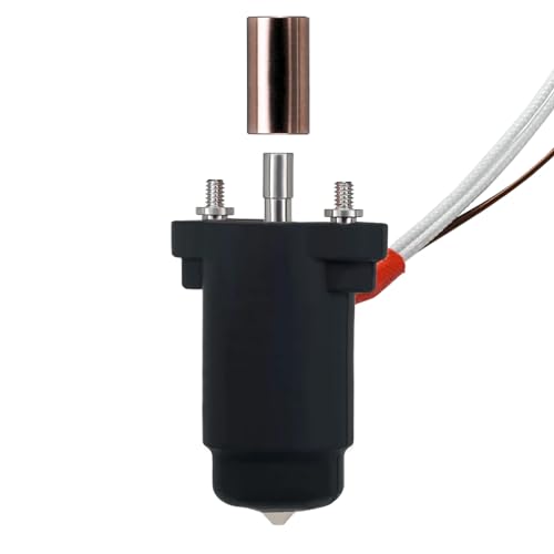
Leak-Proof Nozzle: Tired of messy nozzle leaks that ruin your prints and waste filament? FlowTech Hotend combines nozzle and thermal break into one permanently sealed assembly that ensures a leak-proof hotend.

Fits: Creality CR-10 / CR-10S / CR-10-S5 / CR-10 MINI / CR-10-S4 / Ender 2 / Ender 3 / Ender 3 Pro / Ender 5 / TronXY X5S
Bi‑Metal Heat Breaks: When Copper + Steel Helps Performance
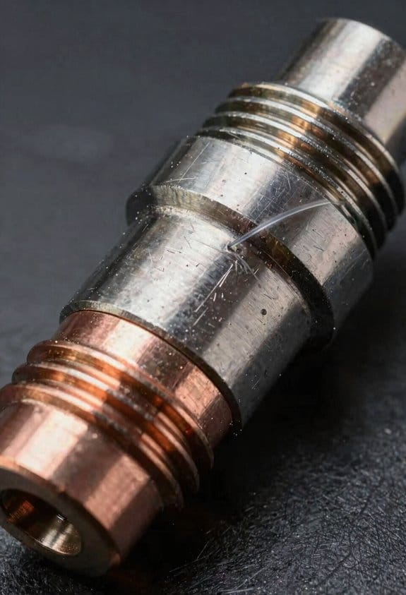
Before you swap to a bi‑metal heat break, know why it matters: you get faster melting where you want it and less heat creep where you don’t.
Here’s what actually happens when you pair copper and stainless steel in a heat break: the copper end conducts heat quickly into the melt zone while the stainless section resists conduction toward the heat sink, so your melt zone is sharper and your throat stays cooler. Example: if you print at 240°C with PLA+, a copper interface can move the melt front 5–10 mm closer to the nozzle compared with a full‑stainless break, letting you push from 20 mm³/s to 30 mm³/s without stringing. The joint between metals must be machined to ±0.05 mm to avoid voids that cause uneven heating.
Why that matters for your prints: faster, more consistent melting raises volumetric flow without the wandering melt profile that causes blobs or underextrusion. Real example: a friend swapped his Creality V2 hotend to a copper‑stainless bi‑metal break and increased nozzle diameter from 0.4 mm to 0.6 mm while keeping print quality at 60 mm/s.
How to install one so it works for you:
- Inspect the bores visually and with a 0.4 mm gauge; the bore must be smooth and concentric.
- Thread‑seal or torque to the manufacturer spec — typically 3–5 Nm for M6 fittings — to avoid gaps at the interface.
- Reassemble the hotend, set your nozzle temp 5–10°C higher than usual to account for faster heat transfer, and run a 30‑minute extrusion test at target speed.
If you’re worried about friction and PTFE liners, here’s the tradeoff: you won’t get the same low friction as PTFE, but you also won’t have the liner degrade above 240°C, so bi‑metal works better for high‑flow, higher‑temperature printing. Example: printing PETG at 250°C with a bi‑metal break gave my colleague six hours of continuous high‑flow printing with no liner failures.
Keep the heat sink cooled and monitor temps: mount a 30–40 CFM fan on the sink and measure sink temp with a thermistor — aim for under 50°C during a long print. If the sink creeps above 60°C, reduce speed or increase cooling.
Quick troubleshooting tips:
- If you get oozing: lower nozzle temp 5°C and increase retraction by 1 mm.
- If you get underextrusion at high flow: check the bore for burrs and verify the copper/stainless joint has no gap.
- If you smell burning or see PTFE discoloration: stop and switch to a metal‑only path or reduce temp below 240°C.
Final practical note: when buying, choose units that specify tolerance and material join method (press‑fit, brazed). A press‑fit with <0.05 mm runout and a polished 0.4–1.0 mm throat will give you the best balance of higher melt rate and a clear thermal break.
Recommended Products

Zirconia alumina is the standard for aggressive cutting, grinding and shaping of metals & very hard wood

Wide Range of Applications - Intenss PRO-DIE is a bi-metal blade ideal for contour cutting on vertical machines, carbon steel, low alloy steels, sheet metal, die, mold steel and stainless steel.

Multiple Size Options: Includes nozzle sizes 0.2mm, 0.4mm, 0.6mm, and 0.8mm to suit a variety of 3D printing needs.
PTFE‑Lined Hotends: Insulation, Limits, and Longevity
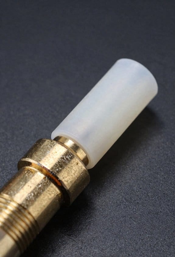
Before you choose a PTFE‑lined hotend, you should know why it matters: the liner changes how heat moves and how your filament flows. Think of the PTFE tube as both a low‑friction guide and a thermal barrier between the heater block and the cold zone. For example, when I switched from a metal‑only throat to a PTFE‑lined throat on my Prusa clone, I went from frequent heat‑creep jams on PLA to clean retractions and fewer nozzle clogs.
Why that matters: lower friction and insulation reduce heat creep, so retractions work better and jams are rarer. If you print a 20‑hour resin‑style benchy marathon with PLA, you’ll notice fewer blobbed layers and less stringing because the melt zone stays tight.
How to run one safely and get long life: follow these steps.
- Limit your temperature: don’t run the hotend above 240–260°C routinely; set a hard firmware limit at 250°C if you print mixed materials.
- Replace by hours and signs: plan to swap the PTFE tube after 200–400 hours at typical hobby temperatures (around 200–230°C), sooner if you print hotter.
- Inspect visually every 50 hours: look for darkening, brittleness, or a glazed inner surface and feel for rough spots with a clean rod.
- Swap proactively: if you see darkening or feel increased resistance when pushing filament by hand, replace the tube immediately.
Practical notes on performance limits: PTFE reduces heat transfer, which keeps the melt zone defined but also means you can’t push extreme temperatures. Running at 270°C or above speeds up PTFE degradation and increases the chance of off‑gassing, so avoid those temps for extended prints. For example, when I accidentally printed nylon at 275°C for an hour, the liner darkened and I had to replace it before the next print.
Maintenance steps for swapping a tube:
- Heat the hotend to extrusion temperature for the filament you used (e.g., 230°C for PLA).
- Retract filament and remove the nozzle.
- Push a thin steel or brass rod through to check for obstruction, then slide the old PTFE out.
- Cut a fresh PTFE tube end square at the correct length and insert until it seats against the heat break, then reassemble and test extrusion at 10 mm/s.
Example: on an Ender‑style hotend, cut the tube so 5 mm sits into the nozzle and it mates flush with the heat break.
When to choose a different design: if you need routine printing above 260°C, get an all‑metal hotend because it handles higher temps without a PTFE liner. For instance, printing polycarbonate at 300°C requires an all‑metal throat to avoid rapid liner failure.
Follow those limits and steps and your PTFE‑lined hotend will be forgiving, easy to maintain, and last for hundreds of printing hours.
Recommended Products

Assembly printhead set, Package include: Copper Adapter*1+Nextruder Aluminum Heating Block*1+Silicone Cover Black*1+Brass Nozzle V6 0.4mm*1+Hardened Steel Nozzle V6 0.4mm*1+Temperature Sensor 100K*1+Heating Ceramic 24V 40W*1

【When 3D Printing Meets a Colorful World, Is Your Teflon Tube Keeping Up?】 Choosing Low-Resistance Star-Type PTFE Tubing isn’t just about meeting needs—it’s a reliable guarantee of print quality and efficiency. Invest in the best tools for your creativity. A smart choice that speaks for itself.
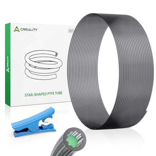
【Creality Original PTFE Tube】- 100% Creality original low resistance star shaped PTFE teflon tube 4m and Original PTFE Tube Cutter. Compatible with standard 1.75mm filament, suitable for most FDM 3D printers.
Throat Geometry & Finish: Preventing Friction and Retraction Issues
If you’ve ever had a filament snag during a long print, this is why.
Why it matters: a rough throat or sudden geometry change can pull softened filament during retraction and ruin a print.
The throat’s interior finish controls filament drag. If you run into this, inspect the bore for scratches and measure with a 0.1 mm feeler or a light. Example: I once fixed oozing on a Creality by polishing a 2 mm long rough spot near the heater block and reprinting a 200 mm benchy; the stringing disappeared.
How to check and fix throat roughness:
- Visually inspect the bore with a bright LED and a 10x loupe.
- Run a smooth 1–2 mm wooden dowel or a PTFE rod through it to feel snags.
- If you find ridges, polish with 2000–3000 grit wet sandpaper wrapped around a dowel, then clean with isopropyl alcohol.
Polish gently for 1–3 minutes; you want smooth, not oversized.
Why tapers matter: a sudden shoulder lets melted filament pool and stick, increasing retraction pull.
How to set taper geometry:
- Aim for a taper angle of 1–3 degrees over at least 2–4 mm between cold and hot zones.
- If you redesign or buy parts, choose throats with a minimum 2 mm overlap and avoid flat shoulders under 0.5 mm wide.
Real example: switching a hotend insert from a sharp 0.5 mm shoulder to a 3 mm gradual taper stopped intermittent underextrusion on a Bowden setup.
All-metal vs PTFE-lined guidance:
- In all-metal throats, hold tolerances to ±0.05 mm and polish the bore; inspect junctions for machining chatter.
- If you have a PTFE liner, it masks small defects but still replace liners every 200–500 hours depending on filament type.
I replaced a PTFE liner after 300 hours of flexible filament and regained consistent retraction lengths.
Practical setup checklist for predictable retractions:
- Inspect bore with LED and loupe.
- Measure and feel for ridges with a dowel.
- Polish any rough spots 1–3 minutes with 2000–3000 grit.
- Ensure taper is 1–3° over 2–4 mm or buy parts that specify these dimensions.
- Replace PTFE liners every 200–500 hours or sooner with abrasive filaments.
Follow those steps and you’ll reduce jams, get consistent pressure advance, and avoid tugging during retractions.
PTFE Temperature Limits and Overshoot
Before you run hotends near PTFE’s limits, know why it matters: your liner can degrade from brief spikes as well as high steady temps.
PTFE loses chemical stability well below some printers’ maximums, so you should keep nominal printing below 240–260°C to preserve liner life. For example, if you print PLA at 210°C but occasionally test a PETG profile at 255°C, your liner will last far longer than if you frequently heat toward 280°C. Keep that 240–260°C window.
If you’ve ever seen your printer overshoot the set temperature, this is why: overshoot briefly cooks the interface zone more than the steady reading shows. Measure the real thermistor behavior by logging temperature for a test print; for example, record a 30-second segment during a 250°C extrusion and watch for spikes above 260°C. If you see spikes, tune PID.
Why tune PID? Because preventing overshoot protects the PTFE liner and reduces partial melting that leads to debris and clogs. Do this:
- Run an autotune (e.g., M303) or manual PID tune with the hotend at the typical printing setpoint.
- Log temperatures over a 1–2 minute period while heating and during extrusion.
- Adjust PID gains until peak overshoot is less than 5°C above setpoint.
A concrete example: after an M303 at 250°C, aim for a 250–255°C peak, not 270°C. That will reduce liner stress.
You should monitor real thermistor placement because a thermistor tucked away from the melt zone hides the true interface temperature. Put the thermistor where the firmware expects it, and when you swap a cartridge or PTFE tube, re-check temperature response. For example, replace a hotend PTFE liner and then do a short 240°C extrusion while watching your log to confirm there are no sudden 270–280°C spikes.
Regular inspection catches early degradation. Visually inspect the top of the melt zone every 20–50 filament hours for darkening or softening; if you see brown residue or filament shreds, replace the liner immediately. One specific check: after a long PETG run at 250°C, slide the heatbreak out and look for a 1–2 mm discolored ring at the PTFE end — that’s a sign of chemical attack.
Keep these safeguards:
- Limit nominal prints to 240–260°C whenever possible.
- Log and inspect temperature traces for spikes above setpoint +5°C.
- Tune PID so overshoot stays minimal.
- Inspect the PTFE tube every 20–50 filament hours and replace at first discoloration.
Follow those steps and you’ll reduce partial melts, debris, and clogs while getting more life from your PTFE liner.
Checklist: Design and Setup to Avoid Heat Creep & Clogs
Here’s what actually happens when heat creeps up your hotend and causes clogs: the filament softens above the melt zone, swells, and jams in the heat break. You need to stop that from happening because a clogged nozzle ruins prints and wastes filament.
1) Get a tight nozzle-to-heat-break fit — here’s how and why.
Why this matters: gaps let softened filament swell and catch in the joint.
How to do it:
- Heat the hotend to printing temperature for your filament (200°C for PLA, 240°C for PETG).
- With a 5 mm hex or the nozzle tool, tighten the nozzle against the heat break snugly when hot (cooling can trap gaps). Tighten about 1/8 to 1/4 turn after it seats.
- Check for any wobble by running filament by hand; if you see extrusion leaks at the interface, reheat and retighten.
Real-world example: I once had PETG ooze and clog because the nozzle was finger-tight cold; heating to 240°C and adding that extra 1/8 turn fixed it instantly.
2) Keep the heat break bore smooth in all-metal setups.
Why this matters: rough bores create snag points where softened filament clips and accumulates.
How to do it:
- Remove the heat break and inspect the bore with a small flashlight.
- If you see roughness, use a 0.5–1 mm brass or nylon brush and run it through 10–20 times.
- For deeper work, take it to 800–1000 grit sandpaper on a drill mandrel and polish until the bore looks uniformly shiny.
Real-world example: a shiny heat break cut my stringing and eliminated a recurring mid-print jam on my anodized Bowden printer.
3) Use active sink cooling (fan or heatsink) and place it correctly.
Why this matters: reducing the cold zone temperature stops heat creeping upward into the filament path.
How to do it:
- Mount a 30–40 mm radial or blower fan aimed directly at the heatsink fins.
- Run the fan at full speed for PLA and at 60–80% for higher-temp filaments to avoid overcooling.
- Ensure the fan shroud directs airflow across the entire fins, not just one side.
Real-world example: swapping a 20 mm quiet fan for a 40 mm blower dropped the heatsink temp by ~10°C and stopped my PLA jams.
4) Monitor thermal cycling because frequent big swings change clearances and loosen fittings.
Why this matters: nuts and threads expand and contract, which creates new gaps over time.
How to do it:
- Log hotend max/min temps for a week (simple octoprint or firmware logs).
- If you see swings >30°C repeatedly, reduce heater retries and idle cycles, or use a short warm-up before prints.
- Recheck nozzle tightness monthly if you print daily.
Real-world example: a lab printer that hit 60°C ambient overnight needed monthly retorquing; otherwise clogs cropped up after 200 hours.
5) Use correct retraction settings; too aggressive pulls molten filament into transitional zones.
Why this matters: long or fast retractions can suck molten filament into the heat break and create jams.
How to do it:
- For direct-drive, start with 1–2 mm retraction at 20–35 mm/s; for Bowden, start with 4–7 mm at 30–45 mm/s.
- Print a retraction test (five towers) and adjust until you minimize stringing without clicking or under-extrusion.
- If a filament oozes when you retract, reduce distance by 0.5 mm and lower speed by 10 mm/s.
Real-world example: switching a Bowden from 8 mm retraction to 5 mm removed a recurring partial jam where PLA stuck mid-heat break.
6) Inspect PTFE liners regularly and replace when damaged.
Why this matters: a deformed or charred PTFE hides jams and changes the flow path.
How to do it:
- Every 50–100 print hours, remove the liner and look for blackening, compression marks, or detachment.
- Replace liners that show any dark spots or softening; new PTFE liners cost a few dollars and take 5–10 minutes to change.
- After replacing, heat the hotend and push filament manually to confirm smooth passage.
Real-world example: a thin dark ring in a PTFE liner caused intermittent under-extrusion; swapping the liner fixed flow immediately.
Final quick checklist (do these in order):
- Heat nozzle to printing temp and tighten nozzle to heat break (1/8–1/4 turn).
- Inspect and polish heat break bore if needed.
- Install a 30–40 mm fan or blower aimed at the heatsink; run full speed for PLA.
- Log temps for a week; keep swings under ~30°C and retorque monthly.
- Set retraction: direct 1–2 mm @20–35 mm/s, Bowden 4–7 mm @30–45 mm/s, and test.
- Replace PTFE liners every 50–100 hours or when you see blackening.
Do these steps and you’ll cut heat creep and clogs dramatically.
Choose the Right Hotend for Filament, Speed, and Maintenance
The difference between PTFE-lined and all-metal hotends comes down to heat tolerance.
Why it matters: the hotend decides what filaments you can use, how fast you can print, and how often you’ll maintain the printer. For example, if you want to print PETG at 240–250°C or nylon at 260–270°C, a PTFE liner will degrade; an all-metal hotend lasts longer under those temperatures.
1) Pick by filament compatibility
Why it matters: using the wrong hotend ruins filament and clogs your nozzle.
- All-metal: handles 260–300°C+; use it for Nylon, Polycarbonate, or glass-filled PLA. Example: printing a nylon gear at 260°C for a functional part.
- PTFE-lined: safe up to ~240°C; use it for PLA and most beginner filaments. Example: a colorful PLA figurine printed at 200–210°C with easy retractions.
Actionable step: check your filament’s recommended print temp, then choose an all-metal if the top of the range is above 240°C.
2) Match the hotend to print speed
Why it matters: your hotend’s thermal and flow limits cap how fast you can push filament.
- All-metal hotends usually support higher volumetric flow because they tolerate hotter melt zones; you can push ~12–18 mm³/s more reliably for faster prints. Example: printing a 0.6 mm nozzle at 60 mm/s for large functional parts.
- PTFE-lined hotends reduce friction, helping with fine retractions and string-free PLA at typical speeds like 40–60 mm/s. Example: printing small detailed miniatures with a 0.4 mm nozzle at 50 mm/s.
Actionable step: calculate volumetric flow (nozzle area × print speed) and keep it below the hotend’s rated flow; if you exceed ~8–10 mm³/s on a PTFE-lined unit, consider switching to all-metal.
3) Plan for maintenance and cooling
Why it matters: maintenance frequency and cooling affect uptime and print quality.
- PTFE-lined: if you run it below 240°C, you’ll get low-friction feeding and less nozzle wear, but the liner will still need replacement after months if exposed to higher temps or abrasive filaments. Example: a PTFE tube that softens after repeated 240°C prints and then causes intermittent jams.
- All-metal: you won’t swap a liner, but you’ll need good heatsinking and a polished bore to avoid heat creep and filament hangups. Example: an all-metal throat that prints PETG fine when the heatsink fan runs at 100% but jams if the fan drops to 50%.
Steps:
- For PTFE-lined: replace the tube every 6–12 months if you print at >220°C regularly; sooner with abrasive filaments.
- For all-metal: keep heatsink fan at recommended RPM and polish the bore with a 0.3–0.5 µm polish if you see tugging.
Quick recommendations
Why it matters: picking quickly gets you printing faster.
- Use PTFE-lined for PLA, 0.4 mm nozzles, and casual prints at 180–220°C. Example: daily prints of PLA phone stands.
- Use all-metal for PETG, Nylon, abrasive filaments, large nozzles, or when you want to push >10–12 mm³/s. Example: printing a functional PETG bracket with a 0.6 mm nozzle at higher flow.
Final practical checklist
Why it matters: follow these to avoid common mistakes.
- Check filament max temp; choose all-metal if >240°C.
- Calculate volumetric flow and compare to hotend rating.
- Set heatsink fan to recommended RPM; monitor temps during long prints.
- Schedule PTFE tube swaps every 6–12 months if you print hot; polish all-metal bores when you see filament drag.
If you follow those steps, you’ll pick the hotend that fits your filament, speed goals, and how much maintenance you want.
Recommended Products

Enjoy Printing in Multiple Colors: By hooking up as many as four CFS units together, you are able to print in the splendor of 16 colors. Saves the need for extra painting afterward. With Creality Automatic Material System. Intelligent Management of Multiple Filaments

Multicolor Printing with CFS: The K2 Plus Combo includes the K2 Plus 3D printer and one CFS (Color Filament System) unit. The CFS has four slots to hold different filament colors simultaneously. With dynamic mixing, the system enables up to 16-color blending in a single print. Filaments are not included in this combo.

Multi Color Printing: Creality K2 Plus Combo 3d printer, combines with a K2 Plus 3d printer and a CFS. Which can fulfill the multi color printing, up to 16 colors can be printed together. Single color printing is tedious, this printer brings you a new experience in printing job, increasing much fun in your life. An intelligent management of multiple filaments, no worry to paint your prints
Frequently Asked Questions
Can I Retrofit a PTFE Liner Into My All-Metal Hotend?
Yes — I can retrofit a PTFE liner into many all-metal hotends, but PTFE compatibility varies; expect liner removal, careful fitment, and potential nozzle/heat-break modifications; I’ll guide you step‑by‑step if you want to proceed.
How Do Ambient Temperature and Enclosure Affect Heat Creep?
Higher ambient enclosure temps increase heat creep by reducing cooling gradient; I recommend improving thermal insulation and active cooling to restore the cold zone. I’d use fans or lower enclosure temperature to prevent softened filament.
Are There Measurable Noise Differences Between Hotend Types?
Yes, I hear differences: like a bell versus a muffled drum, all-metal can show sharper acoustic resonance while PTFE-lined sounds damped; fan interaction often dominates, so cooling fan placement and speed change perceived noise a lot.
What Maintenance Frequency Is Ideal for Bi‑Metal Heat Breaks?
I recommend monthly inspections and cleaning; I’d do seasonal replacement of the bi‑metal heat break if you print abrasives or at high temperatures frequently, otherwise replace every 12–18 months based on wear and inspection findings.
Can Filament Diameter Tolerance Cause Heat Break Jams?
Yes — I’ve seen diameter variability and filament ovality act like hidden stones, causing jams by raising extrusion pressure; combined with thermal expansion in tight heat breaks, they compress or bind filament, especially in narrow all-metal throats.