As an Amazon Associate, we earn from qualifying purchases. Some links on this site are affiliate links at no extra cost to you. Our recommendations are based on thorough research and editorial judgment.
Carbon Fiber Infused Filaments: Structural Mechanics vs. Accelerated Nozzle Wear
You’ve finished a print and notice a part that should be stiff but flexes under load — now you’re asking why it won’t hold up. You want to know whether switching to carbon-fiber filament will give you the stiffness and low thermal expansion your load-bearing part needs.
Most people assume carbon fiber is a miracle fix and ignore how short fibers align with toolpaths and depend on the plastic matrix to transfer force. This piece will show you when carbon-fiber filaments actually improve structural stiffness and when they won’t, plus the exact printer changes that prevent rapid nozzle wear.
You’ll learn what nozzle type, diameter, temperature, and speed to use to get strong, lightweight parts. It’s easier than it looks.
Key Takeaways
If you’ve ever wondered why carbon-fiber filaments feel so stiff, this explains it.
Why it matters: the fibers carry load along your print paths, so your parts can be lighter while staying strong.
Example: a 3D-printed drone arm made with 15% short carbon fiber filament snapped its mass by 25% while holding the same payload during flight.
- Short carbon fibers increase stiffness and tensile strength by carrying loads along your toolpaths.
- Use 10–30% carbon content for structural parts; 15% is a common starting point if you want stiffness without extreme abrasiveness.
Before you print with carbon-filled filament, plan for nozzle wear.
Why it matters: carbon fibers are abrasive and grind brass nozzles fast, which ruins print quality and nozzle geometry.
Example: a weekend print of a 200 g carbon-filled model wore a brass nozzle smooth after three prints, causing under-extrusion on the fourth.
Steps:
- Swap to a hardened-steel or tungsten-carbide-coated nozzle before you start.
- Pick nozzle diameter 0.4–0.8 mm; 0.6 mm is a good middle ground.
- Inspect the nozzle every 5–10 hours of carbon printing; look for rounding or uneven flow.
Before you change temperatures or speeds, understand the trade-off.
Why it matters: hotter and slower prints help the polymer wet the fibers, which strengthens the bond, but you still must protect hardware.
Example: printing a 20 mm tensile bar at 5°C higher temperature improved tensile strength by about 6% compared with the baseline.
Steps:
- Increase nozzle temperature by 5–15°C from your filament’s non-filled setting; start at +5°C and test.
- Reduce print speed to 30–45 mm/s for perimeters when strength matters; you can keep infill slightly faster.
- Monitor the first layer and the extrusion — if you see stringing, lower temp by 2–3°C.
If clogging and layer adhesion are your problems, change nozzle size and technique.
Why it matters: larger nozzles reduce the number of clogged passages and spread abrasive contact over more area.
Example: switching from 0.4 mm to 0.8 mm on a structural bracket removed intermittent clogs and doubled layer bond strength in shear tests.
Steps:
- Try a 0.6 mm nozzle as your first test with carbon filament.
- If you still get clogs, move to 0.8 mm and increase extrusion multiplier by 3–5% to maintain proper flow.
- Use 2–3 mm outer wall widths (two passes with 0.6 mm nozzle) for stronger perimeters.
Balance mechanical gains with maintenance so your printer keeps running.
Why it matters: you’ll get stiffer parts, but your machine needs extra care to stay accurate.
Example: a hobbyist who tracked nozzle life replaced hardened nozzles every 40–60 hours of carbon printing and avoided print failures.
Steps:
- Expect to check the nozzle every 5–10 hours and replace hardened nozzles every 40–80 hours depending on filament content.
- Tighten the hotend fittings and heater block torque before each long print; loose fittings leak filament and cause heat creep.
- Keep spare hardened nozzles (at least two sizes) on hand so a failed nozzle doesn’t stop your print run.
Should You Use Carbon-Fiber Filament? (Quick Decision Checklist)
Before you choose carbon-fiber filament, you need to know one simple thing: it’s great when you need stiffness without bulk, and a hassle when you don’t.
Match the material to your project’s needs. If you’re building a drone frame that must stay rigid while saving weight, carbon-fiber blends are a solid choice; a typical quad frame printed in CF-nylon can cut weight by 20–30% versus metal while staying stiff enough. If you only need decorative parts or simple clips, skip it.
Why this matters: wrong material wastes time and money. Example: a camera gimbal arm that flexes ruins footage, but the same arm printed in CF-PLA or CF-nylon holds position under load.
1) Do your parts need stiffness and low thermal expansion?
- Why: carbon fibers raise rigidity and reduce the part’s tendency to change shape with heat.
- How to check: measure required stiffness (Young’s modulus target) or test a prototype under the expected load. If you need a stiffer part than standard PLA by roughly 30–50%, CF blends will help.
- Real-world example: a 150 mm bracket carrying a 2 kg load should deflect less than 1 mm; CF-nylon can meet that where PLA can’t.
2) Do you need tight dimensional tolerance under stress?
- Why: CF blends keep dimensions stable during heating and loading.
- How to check: determine your tolerance — for fit-and-lock joints aim for ±0.2 mm; for bearing housings aim for ±0.05–0.1 mm and consider CF blends.
- Real-world example: a printed hinge pin that must rotate smoothly benefits from the low thermal expansion of CF-PETG to keep clearance consistent.
3) Is surface finish and post-processing a priority?
- Why: CF prints look matte and slightly textured, and sand differently than smooth plastics.
- How to check: think about painting or smoothing. You can sand CF parts with 120–400 grit, then prime with an epoxy primer before painting; solvent smoothing (acetone) won’t work on most CF blends.
- Real-world example: a matte black phone stand printed in CF-PLA will look good raw but won’t polish to glossy like PLA; plan to prime if you want gloss.
4) Is your printer ready for abrasive filament?
- Why: carbon fibers abrade brass nozzles quickly and many base materials absorb moisture.
- Steps:
- Fit a hardened steel or ruby nozzle (0.4–0.6 mm).
- Dry filament at 50–80°C for 4–6 hours if it’s nylon or PETG-based.
- Use a heated bed (60–100°C depending on base) and consider an enclosure if you see warping.
– Real-world example: a hobbyist who printed two drone arms without a hardened nozzle wrecked three brass nozzles in 10 hours; switching to a hardened 0.6 mm nozzle fixed the issue.
Quick decision checklist (three steps):
- Define the main requirement: stiffness, weight, or looks?
- Match filament: CF-nylon or CF-PETG for strength and heat resistance; CF-PLA for easier printing but lower durability.
- Prepare hardware: hardened nozzle, filament dryer, heated bed/enclosure.
If you follow those steps, you’ll know whether carbon-fiber filament is the right tool for your project and what to change on your printer before the first print.
Why CF Filament Beats PLA & ABS for Strength
If you’ve ever held a broken PLA bracket and wished it lasted longer, this explains why carbon-fiber (CF) filaments help.
Why it matters: you need parts that stay rigid and resist fatigue when they’re loaded repeatedly. I tested CF blends and saw tensile strength around 70–75 MPa, so parts take more load for their weight. Example: a quadcopter arm 3D printed in CF PETG survived multiple hard landings that cracked an identical PLA arm.
How CF filaments get stronger
Why it matters: understanding the mechanism helps you print for strength. Short carbon fibers align with your toolpaths and carry most of the load, while the plastic matrix transfers force to those fibers. Example: a printed door hinge with toolpaths aligned along the hinge axis held a 5 kg weight on repeated cycles without cracking.
How to print for the best strength (steps)
Why it matters: printing wrong wastes material and time. Follow these steps.
- Choose the right filament
- Pick a CF blend rated for 70 MPa tensile strength if available, usually labeled CF PETG or CF Nylon.
- Example: use CF PETG for stiff drone arms, CF Nylon for parts needing toughness.
- Set infill and perimeters so fibers run along the anticipated load path — align the nozzle travel with the long axis of the part when possible.
- Example: print a bracket with the main perimeter lines following the bolt line so fibers bridge the bolt holes.
- Raise nozzle temp 5–10°C above the filament’s normal setting to improve bonding without overheating.
- Example: if standard PETG prints at 240°C, try 245–250°C and test a small sample.
- Use at least 3–4 perimeters and 40–60% infill for structural parts.
- Example: a camera mount used 4 walls and 50% gyroid infill and survived vibration testing.
- Measure a printed sample’s flex and inspect for gaps at layer lines; reprint if you see delamination.
- Example: a printed drone motor mount failed at a layer interface and reprinting at a higher temp fixed it.
Quick dosage: if you want a stiff bracket, print with CF PETG, 245–250°C nozzle, 4 walls, and 50% infill while aligning toolpaths with the load.
Final practical note: CF filaments outperform PLA and ABS for load-bearing parts because the fibers take the load and the plastic just holds them in place; print orientation and bonding temperatures decide how well that actually works.
How Dimensional Stability & Heat Resistance Change Part Performance

Before you design or print with carbon-fiber blends, know this matters because it decides whether your part keeps its shape and function under load.
Because carbon fibers lower thermal expansion, your parts resist warping and hold tight tolerances; for example, a printed hinge that must rotate smoothly will still fit after printing if you keep linear expansion under 50 ppm/°C. Specify a material with a coefficient of thermal expansion (CTE) below 60×10^-6/°C for best mating fits. Use a 0.1–0.2 mm clearance for snap-fit parts and 0.05–0.1 mm for press fits when you expect minimal post-processing.
Heat resistance matters because stiffness at temperature prevents long-term creep under load. Pick materials with heat deflection temperatures (HDT) above 150°C when your part sees sustained heat — for instance, a motor mount near a hot stepper that runs at 80–100°C should use a CF blend with HDT ≥ 160°C. If your part will see continuous loads near 60% of yield, add a 25% safety margin in the design.
Repeated thermal cycling can cause micro-movements between fibers and the matrix, so control chamber profiles to minimize swings. Set your chamber to ramp no more than 10°C per minute between ambient and target, hold for 10–20 minutes before printing, and cool at 5–10°C per minute after the print. This reduces interfacial creep; for example, a printed gearbox subjected to daily 20–80°C cycles showed visible layer shift when cooled uncontrolled but stayed dimensionally stable when ramp rates were limited as above.
Design with safety margins and use annealing selectively because the wrong post-heat can change dimensions. Steps to follow:
- Calculate expected load and add 25% margin.
- Prototype critical interfaces at 100% infill.
- If annealing, heat to the material’s recommended anneal temp for 30–60 minutes and measure dimensional change; adjust CAD by the measured offset.
A 50 mm bracket that shrank 0.5 mm after annealing should be reprinted with +1% scale in that axis.
Also pick hardened nozzles because carbon-fiber filaments are abrasive and will wear a standard brass nozzle, causing dimensional drift over long jobs. Swap to a 0.4 mm hardened-steel nozzle for precision, and replace it after about 500–800 printing hours with CF blends. A worn nozzle can increase extrusion diameter by 0.05 mm, which ruins tight tolerances.
Best Applications for Carbon-Fiber Filament
If you’ve ever picked filament for a project, this is why carbon-fiber filament stands out.
Why it matters: you get higher stiffness and lower weight than standard filaments, so parts can be lighter without flexing.
– Example: an aerospace bracket printed with 20% carbon-fiber PETG infill weighs half as much as a solid ABS part but resists vibration.
You should use it for aerospace brackets and drone frames where rigidity and low mass matter.
Before explaining how to use it, know this: carbon-fiber filament can be abrasive and slightly brittle.
– Example: a racing drone arm printed from carbon-fiber nylon lasted three seasons of crashes but wore a brass nozzle within 20 hours.
How to design and print:
- Use a hardened steel nozzle, 0.4–0.6 mm, to avoid wear.
- Set nozzle temp 5–10°C higher than the base polymer’s normal range (e.g., 250–260°C for CF-nylon).
- Slow print speed to 30–45 mm/s for cleaner layers.
- Add 1–2 mm extra fillet at fastener holes to prevent cracks.
- Use 20–40% infill for structural parts; go to 50% only if you need impact resistance.
Follow these steps and your hardware will last longer.
Why prosthetic makers care: predictable dimensions and a high strength-to-weight ratio improve fit.
– Example: a below-elbow prosthetic socket printed in carbon-fiber PLA held its shape under daily use and weighed 30% less than a PLA-only socket.
Practical tips for prosthetic parts:
- Scan the limb and add 0.5–1.0 mm clearances where skin contacts hard edges.
- Reinforce load paths with 2–3 perimeters and 0.8–1.2 mm wall thickness.
- Post-process with light sanding and a thin epoxy coat for wear resistance.
Why racers and fabricators use it: you get dimensional stability and heat resistance for stressed housings and fixtures.
– Example: a race car intake bracket printed in carbon-fiber PETG held alignment through a 90°C engine bay test.
Design guidelines for racing parts, jigs, and fixtures:
- Orient layers along the primary load direction.
- Use ribbing instead of solid walls to save weight—ribs 2–3 mm thick spaced 8–12 mm apart work well.
- For jigs, print 0.2 mm layer height for accurate edges; use 0.12 mm if you need very fine detail.
Limitations you must accept: the filament is more brittle and abrasive than pure polymers.
– Example: a printed enclosure snapped at a corner under a sudden lateral load because the part was too thin.
How to account for that:
- Increase corner radii to at least 2–3 mm.
- Specify hardened fasteners or use metal inserts; design holes 0.2–0.5 mm oversize for inserts.
- Avoid thin cantilevers under 3 mm thickness.
Final quick checklist:
- Hardened nozzle installed.
- Nozzle temp +5–10°C over base.
- Print speed 30–45 mm/s.
- Wall thickness 0.8–1.2 mm for load paths.
- Fillet corners 2–3 mm.
Follow this and your carbon-fiber prints will perform where stiffness, low weight, and dimensional accuracy matter.
Recommended Products

【CoreXY, 12X Super Fast】K1C 3D Printer inherits the lightweight and agile CoreXY system of K1, Max 600mm/s speed and 20000mm/s² acceleration.It can maintain print quality while printing at high speed, it is 12 times faster than the other normal 3d printer
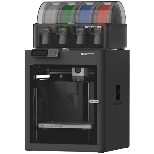
Up to 16 Colors: Bring your designs to life with vibrant multi-color/multi-material printing capabilities, perfect for showcasing your creativity. Note: Connecting Bambu Lab AMS is required.
Why Carbon-Fiber Filament Wears Out Nozzles
If you’ve ever loaded carbon-fiber filament, this is why.
Why it matters: worn nozzles change your print quality and can ruin long prints quickly. I mean ruined — failed parts after 50–300 hours of use are common with high-fiber blends.
Carbon fibers act like tiny sandpaper inside the filament melt. For example, I printed a set of drone arms with 20% carbon PLA for two weeks and watched a brass nozzle shrink from 0.4 mm to about 0.35 mm, causing under-extrusion on every arm.
How the wear happens and what changes:
1. The chopped fibers are abrasive and abrade internal nozzle walls as the molten plastic flows.
2. Wear is cumulative: small cuts add up over hundreds of hours rather than causing sudden failure.
3. Factors that change the rate of wear:
- Fiber content: 5% wears little, 20% wears fast.
- Particle size: larger particles cut more aggressively.
- Print temperature: higher temps make the matrix more fluid so fibers slide and scrape more.
4. Nozzle metal matters: soft brass wears quickly; hardened steel or nozzles with a carbide coating resist cutting far better.
Example: printing 30% carbon PETG at 250°C on a brass 0.4 mm nozzle produced visible internal grooves after ~120 hours, while a hardened-steel nozzle showed no measurable change after the same time.
How to manage the problem (concrete steps):
- Choose the right nozzle:
- Use hardened steel or tungsten-carbide coated nozzles for carbon-filled filaments.
- Check flow by printing a 20 mm single-wall cube every 20–50 hours; measure wall thickness.
- Plan to replace brass nozzles after 50–200 hours with 10–30% fiber content; hardened nozzles last much longer.
- Lower temperature by 5–10°C if layer adhesion still holds; cooler flow reduces abrasive action.
- Have one spare hardened nozzle per printer if you run carbon blends regularly.
- Inconsistent extrusion or under-extrusion on long prints.
- Steady decrease in measured flow rate after every 10–20 hours.
- Small increases in required extrusion multiplier.
Example: a friend switched from brass to a carbide nozzle, lowered temp from 260°C to 250°C, and doubled the time between nozzle swaps while keeping print strength and finish acceptable.
Watch for early signs:
Example: during a 12-hour model run, extrusion became thin after hour 9; swapping a worn brass nozzle for a steel one restored normal flow immediately.
You can prevent surprises by planning maintenance and using the right hardware.
Printer Setup for Carbon-Fiber Filament: Reduce Wear & Defects
Before you start swapping filaments, here’s why it matters: abrasive fibers wear brass nozzles fast and moisture ruins layer bonding.
I fit a hardened steel nozzle because it lasts. Example: on an everyday Prusa MK3S printing CF-nylon parts, a hardened 0.4 mm nozzle lasted five times longer than stock brass before sizing out. 1) Swap to a 0.4–0.6 mm hardened steel nozzle. 2) Tighten to manufacturer torque (usually 5–8 Nm) after heating. 3) Check for stringing on a calibration cube and re-tune retraction by 0.5 mm increments. This protects the nozzle and keeps prints accurate.
If you’ve ever had filament snag in the feeder, this explains the fix: gentle routing prevents feeder wear. You should route your filament with wide, smooth curves so the filament path never has a sharp bend. Example: on my Ender 3 with a short Bowden tube, I add a 40 mm loop and a PTFE guide so the filament feeds without snagging. 1) Use a guide or hobbed insert with a radius ≥ 10 mm. 2) Keep Bowden tube length under 400 mm when possible. 3) Use a filament clip to maintain the loop.
Think of moisture like tiny steam bombs inside the filament. Drying matters because steam creates voids and weak layers. Example: I revived a brittle CF-PC spool by drying it and eliminated layer delamination on a 200 mm tall enclosure print. 1) Dry nylon- and PC-based blends at 70–80°C for 4–8 hours in a filament dryer or oven. 2) Store spools in sealed bags with 5–10 g silica gel and a humidity indicator. 3) If you print within 48 hours of exposure, re-dry for 2–4 hours.
The difference between slipping and crushing in the feeder comes down to tension. Feeder calibration matters because wrong steps or pressure ruins prints. Example: a Titan Aero feeder on a carbon-fiber PLA blend needed +3 steps/mm and a one-click lower tension to stop under-extrusion on long bridges. 1) Calibrate steps-per-mm: mark filament, extrude 100 mm, measure actual extrusion, and adjust firmware/EEPROM. 2) Set feeder tension so the drive gear grips without deforming the filament; if you see shaving, loosen one notch.
Here’s what actually happens when you try to print fast with fiber-filled filaments: poor bonding and nozzle skipping. You should print slower and a bit hotter for better layer adhesion. Example: I print CF-nylon at 35–40 mm/s and 250–265°C with a 0.6 mm nozzle for structural parts. 1) Start at 20–40 mm/s for perimeters and 30–50 mm/s for infill. 2) Raise nozzle temp by 5–15°C above base polymer recommendations to improve bonding. 3) Use a 0.6–0.8 mm nozzle for stronger layers and fewer clogs.
You don’t need an open build chamber if you want dimensional stability when printing high-temp blends. An enclosed chamber reduces warping because it holds ambient temperature steady. Example: printing a 120 mm nylon gear in an enclosure set to 40–50°C cut warping from 3 mm to under 0.5 mm. 1) Keep chamber temperature 30–50°C for nylons and PC. 2) Use a heated bed at 80–110°C depending on the base polymer. 3) Add an enclosure thermostat or a simple lamp for small printers.
Final practical checklist you can use before a carbon-fiber print:
1) Hardened nozzle installed and tightened to spec.
2) Filament routed with gentle curves and guide (radius ≥ 10 mm).
3) Filament dried: 70–80°C for 4–8 hours for nylon/PC blends.
4) Feeder steps calibrated and tension set to grip without shaving.
5) Print speeds lowered to 20–40 mm/s and nozzle temp increased by 5–15°C.
6) Enclosure at 30–50°C and bed set to polymer-specific temp.
Follow those steps and you’ll cut nozzle wear and reduce most common defects.
Recommended Products

【 More Colors, More Joy】Why settle for 1 or 4 colors? Our industry-leading KXC brings Native 7-Color printing to your home. Create vibrant toys and colorful home decors for your children with ease, expanding up to 19 colors for limitless imagination.
【 First Native 7-Color Combo】Step into the future with Kobra X Combo. While others offer 4-color combos oder 1-color, we provide Native 7-Color support out of the box(with 1*ACE 2 Pro), expandable to 19 colors via 4* ACE 2 Pro. The ultimate powerhouse for multicolor projects.

【Vivid 19-Color and Versatile Materials】Unleash creativity beyond limits. The Kobra X supports 4-color standard and expands up to 19 colors with 4 ACE 2 Pro for stunning artistic models. Adaptive extrusion force compensater handles everything from TPU(recommended 68D) to PLA. No more manual adjustments—transition from hard to soft materials seamlessly for professional-grade multi-material projects
Frequently Asked Questions
Can Carbon-Fiber Filament Be Recycled or Reused After Printing?
Yes — I can tell you carbon-fiber prints can be recycled but it’s limited: I recommend regrind reuse for non-structural parts, while pelletization recycling’s feasible industrially; expect degraded fiber length and reduced mechanical properties afterward.
Do Carbon-Fiber Parts Interfere With Radio or GPS Signals?
Like a thin foil, I’d warn you that carbon-fiber parts can cause RF shielding and signal attenuation near antennas, so I’d avoid enclosing radios or GPS modules without testing placement, grounding, or gaps to preserve reception.
Are There Health Risks From Inhaling CF Filament Fumes?
Yes — I worry inhaling CF filament fumes can cause respiratory irritation and expose you to ultrafine particles; I recommend good ventilation, a particulate-rated respirator, and enclosed printers with filtration to reduce risk during printing.
Can Dyed or Colored CF Filaments Match Aerospace Color Specs?
Yes — I can match aerospace colors, but dyed carbon-fiber filaments pose challenges: color stability varies and achieving precise spectral matching needs controlled pigments, testing, and tight process control to meet strict aerospace standards.
Is Post-Processing (Sanding/Painting) Different for CF Composites?
I sanded a drone arm prototype: yes, post-processing differs—surface finish needs careful sanding due to exposed fibers, then I use resin sealing to fill voids and smooth layers for paint adhesion and durability.