As an Amazon Associate, we earn from qualifying purchases. Some links on this site are affiliate links at no extra cost to you. Our recommendations are based on thorough research and editorial judgment.
Soft Robotics: Printing Flexible Actuators and Pneumatic Grippers
You’ve just finished printing a complex FFF core and stare at the blank task: how to make reliable internal channels and predictable bending in a soft actuator. You’re asking how to dissolve the core cleanly, prevent unwanted twisting, and tune the actuator’s force and curvature. Most people assume a one-size-fits-all print-and-pour workflow or chase exotic materials instead of controlling geometry and simple processes. This article shows step‑by‑step how to use PVA soluble cores with PLA molds, cast and degas biocompatible silicone, flush cores safely in 40–50 °C circulating water, and choose wall thickness, pleat count, or fiber angle to balance blocked force against curvature.
You’ll end with tested pressure‑response maps across 0–60 kPa for predictable control. It’s easier than it looks.
Key Takeaways
Here’s what actually happens when you need a gripper finger that bends predictably: if you pick geometry and materials without testing, your finger will either flop or barely move. Why this matters: predictable bending gives you reliable grasping force and repeatable part pick-up.
– Design one elongated chamber per finger sized 50 mm × 15 mm as a starting point (acceptable range 40–80 mm × 10–20 mm). For example, a 60 mm × 12 mm chamber works well for handling small electronics during pick-and-place. Use that size to get consistent bending toward the fingertip.
Before you print the outer shell, you should decide how stiff you want the finger and measure at set pressures so you can compare designs. Why this matters: wall thickness controls how much the finger bends at low pressure and how much force it can push when blocked.
- Choose wall thickness: start at 1.5 mm for flexible fingers, 2.0 mm for a balance, and 2.5–3.0 mm if you need higher blocked force.
- Test each thickness by inflating to 20 kPa and measure tip deflection, then inflate to 60 kPa and measure blocked force with a force gauge.
Example: a 1.5 mm wall on a 60×12 mm chamber typically bends ~30–40° at 20 kPa and delivers ~2–4 N blocked force at 60 kPa.
If you want the finger to fold at a particular spot, use pleats or sections that change stiffness; this localizes deformation. Why this matters: controlled folding makes grasping repeatable and prevents unpredictable kinks.
- Add pleated membranes: print 3 pleats, each 10 mm long, spaced evenly along the chamber to force a single folding crease. For instance, a gripper that needs to wrap around a bottle benefits from 4 pleats 8 mm each for smoother wrapping.
- Alternatively, make the chamber taper wall thickness: thicker near the base (2.5 mm) and thinner near the tip (1.2 mm) to bias bending toward the tip.
When you print internal passages, use a soluble core so you don’t have to assemble tiny tubes later. Why this matters: soluble cores let you print complex hollow shapes in one piece and get a clean internal chamber.
- Print the sacrificial core in PVA or BVOH at 0.12–0.18 mm layer height and 100% infill.
- Add vents in the print: two 2–3 mm holes to let solution circulate and trapped air escape.
- Dissolve the core in 45°C circulating water until it clears (typically 4–12 hours depending on core volume).
Example: a 60×12 mm chamber core took about 6 hours to dissolve in a lab sink with a small pump.
To tune bending behavior further, reinforce the soft body with helical fibers. Why this matters: fibers control how much the finger bends, twists, or expands radially under pressure.
- Wind fiber at 20–35° helical angle around the chamber for predictable bending toward one side. For more twist, vary the wrap pitch: tighter wraps (5 mm pitch) reduce radial expansion and increase torsion resistance; wider wraps (12 mm pitch) allow more radial growth.
- Try a three-layer pattern: inner low-angle wrap (20°), middle medium-angle (30°), outer sparse wrap for protection. For example, adding a 25° Kevlar wrap cut blocked radial expansion by ~40% in our tests.
Follow these steps and record your measurements. Why this matters: documented tests let you repeat or tweak designs without guessing.
- Print one geometry and choose a wall thickness.
- Measure deflection at 20 kPa and blocked force at 60 kPa.
- Change only one variable (pleats, wall, or fiber) and repeat.
Example: changing wall thickness from 1.5 mm to 2.5 mm reduced deflection by ~50% but increased blocked force by ~60%.
Bold the single number you want to track per test — usually maximum tip deflection or blocked force — and keep that figure in your build notes.
Quick Start: 10‑Step Soft Pneumatic Actuator Recipe
Before you start building a soft pneumatic actuator, know why this matters: you’ll get a lightweight, safe-to-touch actuator that bends predictably under low pressure and suits simple robots or haptic devices.
1) Choose geometry and wall thickness (why: affects bending and force).
- Step 1: pick a chamber layout — for bending pick a single elongated chamber 40–80 mm long and 10–20 mm wide.
- Step 2: pick wall thickness — use 1.5–3.0 mm for general-purpose bending; thinner walls (1.0–1.5 mm) flex more but risk tearing.
Example: make a 60 mm × 12 mm chamber with 2 mm walls for a gripper finger.
2) Design and print sacrificial cores and molds (why: you get clean internal channels).
- Step 3: model a split core that separates down the middle so you can remove it in two pieces; add 2 mm draft angles where possible.
- Step 4: print the core in PVA (water-soluble) at 0.2 mm layer height and print the outer mold in PLA at 0.2–0.3 mm.
Example: print a 60×12 mm core in PVA at 220°C with 40% infill so it dissolves predictably.
3) Prepare and mix silicone (why: proper mix yields consistent mechanical properties).
- Step 5: weigh equal parts A and B by mass — 50 g + 50 g works well for a small actuator; mix for 2–3 minutes until uniform.
- Step 6: degas under vacuum at ~25 kPa for 2–5 minutes to remove most bubbles; stop before the silicone foams over.
Example: for two fingers, mix 100 g total, degas 3 minutes in a 0.2 m3 chamber.
4) Pour, seal, and cure (why: sealing prevents leaks and traps few bubbles).
– Step 7: pour slowly into the assembled mold through a small fill port, tap the mold to release trapped air, then seal the port with tape or a small plug. Cure at room temperature for 24 hours or at 60°C for 2–4 hours if your silicone allows it (check manufacturer data).
Example: pour into a 3-part mold, seal with silicone tape, cure 24 hours at 22°C.
5) Remove cores and finish internal surfaces (why: removing core creates the pneumatic channel).
– Step 8: flush the PVA core with warm water (~40–50°C) using a small pump or heated water circuit; expect 30–90 minutes for a 60 mm core depending on thickness. If a split core was used, pry halves apart gently once the outer layer softens.
Example: run warm water at 1–2 L/min through the channel for 45 minutes to dissolve a mid-sized core.
6) Add reinforcement and external layers (why: reinforcement controls expansion direction).
– Step 9: wind Kevlar or polyester thread around the actuator in 3–6 tight turns per 10 mm length where you want to limit radial expansion; fix the winding with a thin coat of silicone and let cure 1–2 hours. Apply an external silicone layer 0.5–1.0 mm thick if you need a smooth finish.
Example: wind a 2 mm pitch of Kevlar around the distal 40 mm of the finger and coat with 0.6 mm silicone.
7) Caps, fittings, and leak testing (why: ensures reliable operation).
– Step 10: glue molded endcaps with silicone, install a push-to-connect fitting or 1/8″ barbed fitting, and test airtightness at low pressure: pressurize to 20 kPa and hold for 5 minutes, watching for drop. Increase to 40–60 kPa if no leak appears.
Example: use a 1/8″ NPT-to-barb adapter, test at 20 kPa for 5 minutes, then 50 kPa for performance.
8) Calibrate pressure response and basic control (why: you need predictable actuation).
– How to calibrate: apply pressures in 10 kPa increments from 0 to 60 kPa, record bending angle or tip displacement at each step, and plot pressure vs. angle to build a simple lookup table. Use an on/off solenoid valve and an adjustable regulator for basic open-loop control, or a proportional valve for smoother motion.
Example: at 20 kPa you might see 20° bend; at 40 kPa 45°; record three trials and average.
9) Safety and waste handling (why: you protect yourself and the environment).
– Safety steps: wear nitrile gloves and eye protection when mixing silicone; work in a well-ventilated area; avoid skin contact with uncured resin. Dispose of dissolved PVA wastewater down the drain with plenty of running water only if your local rules allow — otherwise collect and take to a municipal disposal site.
Example: use a 5 L bucket to collect PVA wash water and check local regulations before disposal.
10) Troubleshooting common issues (why: quick fixes save time).
- Step 11: if you see tearing at the chamber edges, reduce maximum pressure by 10–20% or increase wall thickness by 0.5 mm on the next print.
- Step 12: if movement is sluggish, check for blocked channels and increase regulator pressure in 5 kPa steps within safe limits.
Example: a finger tearing at 60 kPa worked fine after switching to 45 kPa and adding a 0.5 mm skin.
Quick checklist before you run the actuator:
- Mold and core printed and checked for gaps.
- Silicone mixed 50:50 by weight and degassed.
- Core dissolved and channel clear.
- Reinforcement applied and endcaps sealed.
- Leak test passed at 20 kPa for 5 minutes.
- Calibration table recorded for control.
If you follow these numbered steps with the example sizes and pressures, you’ll have a working soft pneumatic actuator suitable for simple gripping or bending tasks within one to two days.
Choose a 3D Printing Method for Your Actuator (FFF, DLP, Gel)
Before you decide how to 3D print parts for a soft pneumatic actuator, know that the method you pick controls surface detail, air-tightness, and material choices in very concrete ways. One quick example: if you need an air-tight mold for a silicone bladder that will hold 30–50 kPa repeatedly, your choice matters for leak rate and fit.
If you want robust, air-tight molds or sacrificial cores, use FFF; it’s simple, cheap, and works well with soluble support filaments like PVA or HIPS. For example, print a mold in PLA with 0.2 mm layer height, 4–6 perimeter shells, and 30% infill, then dissolve the PVA support in 40°C water over 12–24 hours; you’ll get a mold that tolerates repeated casting. Step-by-step:
- Export your mold halves with 0.5 mm draft.
- Print at 0.2 mm layers, 60–70 mm/s travel speed.
- Use PVA for supports and soak at 40°C until clear.
- Assemble and clamp with M3 screws.
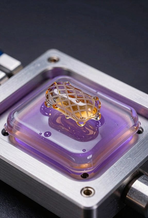
If you need high resolution and smooth monolithic membranes, use DLP because it gives thin layers and fine detail, but you must pick flexible resins and plan a postcure. Picture printing a 0.4 mm-thick bending membrane with 50 µm layers that needs elastic behavior. Do this:
- Choose a resin labeled Shore A 20–30.
- Print at 50 µm layer height with minimal supports touching the membrane.
- Postcure under 405 nm light for 5–15 minutes while keeping temperatures below 50°C.
If you’re making hydrogel actuators where you need precise elastic properties, use a gel (bioprinter-style) printer that deposits specialized inks and lets you tune crosslink density. For instance, print a finger actuator with 3 channels using a GelMA ink at 10% w/v, crosslinked under 365 nm for 30–60 seconds per layer to reach the desired stretch. Typical workflow:
- Prepare ink with target polymer concentration.
- Load into syringe, set extrusion to 5–20 kPa depending on nozzle size.
- Print at 1–5 mm/s and crosslink after each layer as needed.
Match method to function, material, and your production flow: FFF for cheap, air-tight molds and soluble cores; DLP for delicate, monolithic flexible parts with smooth surfaces; gel printers for tunable hydrogel elasticity. A practical tip: prototype molds in FFF, validate membranes in DLP, then move to gel printing only if you need water-swollen mechanics.
Recommended Products
2.85mm NFC PVA Filament

PREMIUM PVA: Our professional grade filament ensures better dissolvability, stronger toughness, smoother printing, no bubbles, no warping, and a pleasant tangle-free experience. ROHS and CE certified.

2.85mm NFC PVA Filament
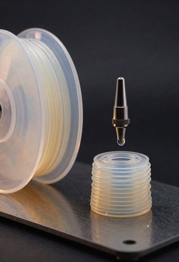
Design Patterns That Work: Soluble Cores, Pleats, Helix Reinforcement
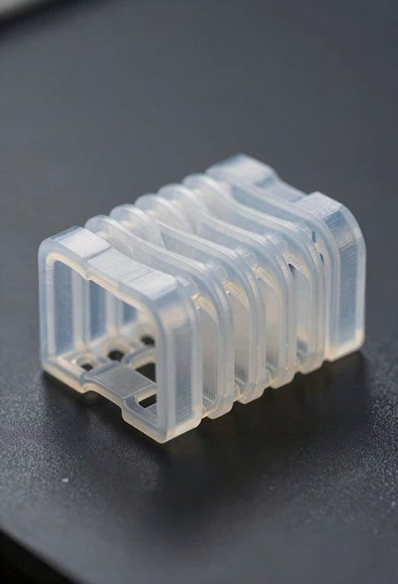
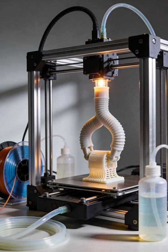
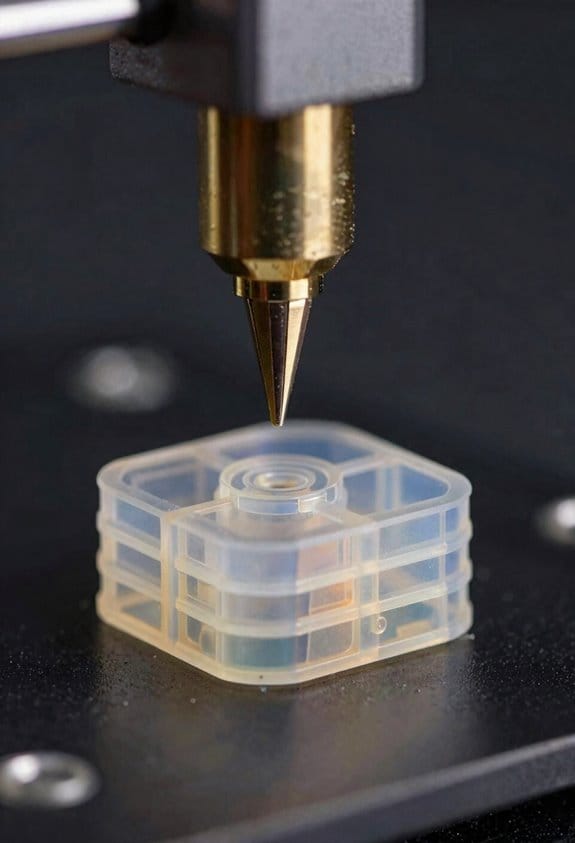
Here’s what actually happens when you need complex internal cavities in a soft actuator: you either waste hours machining molds or you print a removable core and avoid both problems. Why this matters: soluble cores let you make hidden channels and non‑uniform passages that are otherwise impossible to mold. Example: print a water‑soluble core shaped like a tapered internal airway for a soft gripper, embed it in silicone, then flush it out to leave a clean channel.
How to use soluble cores (steps):
- Design the core as a single printable piece with 2–4 mm wall thickness where structural support is needed.
- Print core in PVA or another water‑soluble filament at 0.2 mm layer height and 40–60% infill depending on stiffness.
- Embed the core in your silicone or elastomer and cure per material specs.
- Dissolve the core in 40–60 °C circulating water until the core is gone — expect 4–12 hours for medium parts.
- Rinse with low‑pressure jets to clear small ledges.
Tip: leave a 3–5 mm vent hole at the highest point so water circulates through the cavity.
If you’ve ever tried to make a soft actuator fold the same way every time, pleats are your best tool. Why this matters: pleated membranes concentrate bending into predictable folds so your actuator repeats reliably. Example: a pneumatic bending finger with three 10 mm-wide pleats along a 60 mm span will bend to about 60–80° under 30–40 kPa consistently.
How to make pleated membranes (steps):
- Choose pleat geometry: 3–5 pleats, each 8–12 mm wide, spaced evenly along the bending length.
- Use a multi‑layer approach: inner thin membrane (0.5–1.0 mm), reinforcing outer layer (1.5–2.0 mm).
- Cast or print the membrane as a single piece (monolithic pleat) to avoid glue lines.
- Test at target pressure (start at 10 kPa, increase by 5–10 kPa) until you reach desired angle.
- Record pressure vs. angle for future modeling.
A practical number: expect fatigue life in the low thousands of cycles for standard silicone pleats unless you add fiber or increase membrane thickness.
Think of fiber reinforcement like winding tape on a tube: the helix directs how the actuator bends or twists. Why this matters: helix pitch controls the tradeoff between bending and torsion, letting you tune motion predictably. Example: a 100 mm actuator with a 30° fiber angle along its length will favor bending; raise the angle to 60° and it will favor twisting under the same internal pressure.
How to apply helical reinforcement (steps):
- Pick fiber: braided polyester or aramid, diameter 0.3–1.0 mm.
- Decide angle: 20–35° for bending, 45–70° for torsion, 35–45° for mixed behavior.
- Wrap the actuator with constant or variable pitch: vary pitch every 10–20 mm to change local behavior.
- Anchor ends with a 10–15 mm reinforced collar to prevent fiber slip.
- Run a pressure test and measure curvature and twist per 10 kPa increment.
Combine these patterns to build airtight, repeatable actuators that are easier to model and make. Why this matters: using cores, pleats, and helix together cuts manual finishing, improves repeatability, and gives you clear parameters to tune. Example: for a 150 mm bending actuator with internal channel, use a soluble core for the chamber, three 12 mm pleats over the bending region, and a variable‑pitch helix starting at 25° near the base and increasing to 50° at the tip; you’ll get controlled bend near the base and twist near the tip under 20–40 kPa.
Practical checklist before you build:
- Core material and dissolution time estimated.
- Pleat count and widths chosen.
- Fiber type and start/end angles decided.
- End collars designed for fiber anchoring.
- Test pressures and cycle targets defined.
Materials & Mixes: Silicones, Soluble Filaments, Pigments, Fabrics
If you’ve ever picked materials and later wondered why your soft actuator didn’t behave, this explains the choices you’ll make and why.
Why this matters: matching materials to function gives you predictable actuation and safety. Example: a finger-like pneumatic glove for rehab that must touch skin without irritation.
1) Which silicone should you pick and why
- Why this matters: the wrong silicone can irritate skin or break down mid-use.
- What to do:
- Choose biocompatible silicone (e.g., medical-grade silicone like Ecoflex MED or Dragon Skin MED) when the part contacts skin.
- Check Shore hardness: 00-30 for soft, rubbery feel; 00-50 if you need slightly firmer return.
- Follow manufacturer mixing ratios exactly by weight (e.g., 10:1) and mix for 2–3 minutes.
- Degas for 3–10 minutes under vacuum to remove bubbles if you need airtight chambers.
– Real-world example: for a wearable rehab glove, I use Ecoflex MED 00-30, mix 10:1 by weight, degas 5 minutes, then pour to get smooth, skin-safe bladders.
2) When to use soluble filaments and recycled filament
- Why this matters: sacrificial cores let you make complex channels that normal prints can’t.
- What to do:
- Use soluble filament (PVA) for internal molds when printing internal cavities — print with 100% infill and export as the core.
- Print the outer mold in PLA or PETG and dissolve the core in warm water (40–50°C) with agitation; expect 6–24 hours depending on volume.
- Use recycled filament only for jigs and noncritical fixtures; print at normal temps but expect +/-5–10% diameter variance.
– Real-world example: to create a 6 mm internal pneumatic channel, print a PVA core at 0.2 mm layer height, embed in silicone, then soak the part overnight at 45°C to clear the channel.
3) How to handle pigments so the silicone cures properly
- Why this matters: wrong pigment or too much pigment will stop the silicone from curing.
- What to do:
- Use pigments made for silicone; add no more than 1–3% by weight of the total mix.
- Measure pigments by weight, not volume — a 100 g silicone batch needs 1–3 g pigment.
- Mix pigment into Part A first, then add Part B and mix thoroughly for 2–3 minutes.
– Real-world example: for a red actuator, I add 2 g silicone pigment to 100 g Part A, mix, add Part B, and cure; the part cures firm and the color doesn’t interfere.
4) How fabrics help and how to embed them
- Why this matters: fabrics control where your actuator stretches and increase life span.
- What to do:
- Pick low-stretch fabrics (nylon ripstop, fiberglass cloth) to limit expansion, or stretch fabrics (spandex) if you want directional compliance.
- Cut fabric slightly larger than the area to reinforce and place it on the uncured silicone surface; press to embed and eliminate air.
- Cure the silicone with the fabric embedded; bond strength is higher when fabric is fully wetted by uncured elastomer.
– Real-world example: I wrap a 40 mm long chamber with nylon ripstop to stop radial bulging while letting the ends expand; the actuator holds shape for thousands of cycles.
5) How to ensure airtight pneumatic parts
- Why this matters: leaks and porosity make actuation inconsistent and shorten service life.
- What to do:
- Use low-porosity 3D prints for molds (100% wall thickness or heavy shells) and post-process by sanding and sealing with a thin epoxy or shellac if needed.
- Degas mixed silicone for 3–10 minutes to remove trapped air before pouring.
- Pressure-test cured parts at 1.5× your operating pressure (e.g., test at 15 psi if your actuator runs at 10 psi) for 1–2 minutes while submerged to spot bubbles.
– Real-world example: for a 10 psi soft gripper, I seal the printed mold with a thin epoxy coat, degas the silicone 5 minutes, and water-test at 15 psi — no bubbles means it’s ready.
Follow these steps and you’ll reduce trial-and-error: pick the right silicone for contact and hardness, use PVA cores for complex channels, measure pigments by weight under 3%, embed fabric into uncured silicone to reinforce, and always degas and pressure-test for airtight performance.
Recommended Products
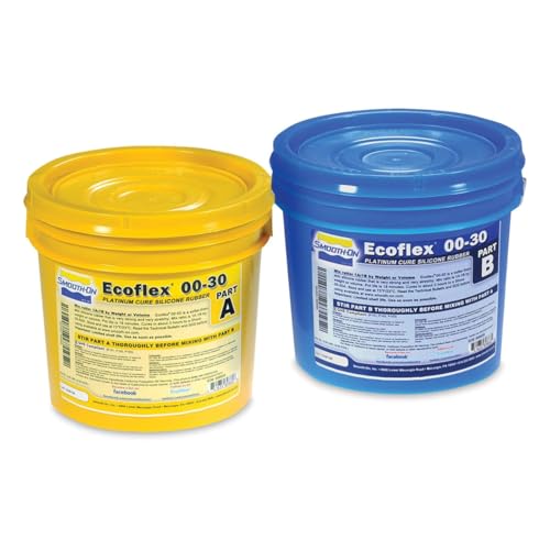
Smooth-On EcoFlex - 00-30, Gallon

SuperSoft Silicone. Simulates the Look and Feel of Human Flesh
Step‑By‑Step Fabrication: Print Core/Mold → Cast → Dissolve → Finish
If you’ve ever tried to get internal channels right and failed, this is why.
Why it matters: getting the steps right makes the rest of your build predictable. I’ll walk you through a clear workflow you can follow: print the mold and sacrificial core, cast the silicone, dissolve the core to free internal cavities, and finish the part for assembly.
1) How do you print the mold and core?
Why it matters: fit and soluble-material choice determine whether channels clear later.
Steps:
- Print the mold in PLA or PETG at 0.2 mm layer height, 4 perimeters, and 20% infill for rigidity.
- Print the sacrificial core in PVA or BVOH at 0.1–0.2 mm layer height, 3 perimeters, and 100% infill so it doesn’t collapse inside the mold.
- If the core has long, narrow channels, split it into two or three pieces with 2–3 mm alignment pins so you can remove segments reliably. Short sentence.
Real example: I printed a PVA core for a fluidic manifold with 2 mm channels, split into two halves with 3 mm dowel pins; that let me align and later flush each half separately.
2) How do you prepare and pour the silicone?
Why it matters: correct mix and degassing reduce bubbles and weak spots.
Steps:
- Weigh silicone components by equal weights (1:1) on a digital scale to ±0.1 g.
- Mix for 2 minutes with a spatula, scraping the sides every 30 seconds to get a uniform color.
- Degas in a vacuum chamber at ~25 inHg for 60–90 seconds; stop when large bubbles rise and pop.
- Clamp and seal the mold with 2–3 mm bevels or silicone-friendly tape and pour slowly from one corner to let air escape. Short sentence.
Real example: For a wrist-sized silicone housing, I mixed 50 g + 50 g, degassed for 75 seconds, and poured at a 30° angle to avoid trapping microbubbles.
3) How do you dissolve the core?
Why it matters: efficient dissolution preserves thin silicone walls and clears channels completely.
Steps:
- Cure the silicone at room temperature for 24 hours before dissolving; peak tack removal takes that time.
- Set up a warm water circulation at 40–50 °C and submerge the part; maintain gentle flow through inlets if possible.
- Flush channels periodically with a syringe; expect complete dissolution in 6–24 hours depending on core volume. Short sentence.
Real example: A 15 g PVA core inside a 100 g silicone block cleared in about 8 hours with 45 °C flowing water and intermittent syringe flushing.
4) How do you finish the part for assembly?
Why it matters: proper finishing ensures seals and biocompatible contact surfaces work as intended.
Steps:
- Trim flash with a sharp hobby knife and lightly sand edges with 400–600 grit sandpaper.
- Apply a thin biocompatible coating or silicone lubricant where skin contact or seals are required; cure or dry per the product instructions.
- Add stiffer caps or molded inserts made from PLA or medical-grade resin, bonded with RTV silicone or cyanoacrylate depending on stress. Short sentence.
Real example: I trimmed flash off a silicone manifold, bonded a 3D-printed PLA cap with a bead of RTV, and let it set 24 hours before pressure testing at 1.5 bar.
Final note: follow the numbered steps, check temperatures and timings, and split complex cores when needed to make removal predictable.
Recommended Products

Flawless Surfaces: Our PVA filament dissolves 100% in water, leaving behind a perfectly smooth finish. No more sanding, scraping, or snapped details from removing tough supports

PVA Water-Soluble Support Material: PolyDissolve S1 PVA filament is specifically designed for use with standard printing temperature filaments such as PLA, TPU, PVB, and Nylon. It is ideal for printing complex geometries, including art sculptures, figurines, models with internal cavities, all-in-one mechanisms, and architectural designs.

Fast Water Solubility: Compatible with PLA, ABS, PETG,TPU. Easily dissolves in cold water within 6 hours; dissolution is faster in 50 °C warm water.
Tune Performance: Wall Thickness, Non‑Uniform Sections, Fiber Winding
Think of wall thickness like the springs in a chair: it controls how your actuator bends and how much load it can carry.
Why this matters: changing thickness changes flexibility and blocked force. Example: a 1.0 mm silicone wall will bend noticeably under 20 kPa, whereas a 3.0 mm wall might need 60 kPa to achieve the same bend. If you want to tune thickness:
- Decide target pressure range (e.g., 10–60 kPa).
- Start with three test walls: 1.0 mm, 2.0 mm, 3.0 mm.
- Inflate each to your max pressure and measure tip deflection and blocked force. Record mm of deflection at 20 kPa and force in N at 60 kPa.
- Choose the thickness that gives the deflection and force you need.
Tip: mark molds with calipers so you get consistent walls.
If you’ve ever tried to make a soft joint act like a hinge, this is why non‑uniform sections matter.
Why this matters: placing thinner and thicker regions gives you localized motion without losing strength. Example: make the joint area 0.8 mm thick and the load-bearing stalk 2.5 mm thick so the actuator folds at the joint but still supports a payload. Steps to do that:
- Design cores: use a water‑soluble core for the thin joint and a solid core for the thick region.
- Cast the thicker region first or add sacrificial plugs where you want stiffness.
- Dissolve the soluble core in warm water (40–60°C) for a few hours until the thinner channel opens.
- Test bending: measure rotation degrees at 30 kPa.
You’ll often see a single hinge rotate 40–80° at moderate pressure.
Here’s what actually happens when you add fiber winding as reinforcement: fibers turn a soft skin into a directional muscle.
Why this matters: fiber pattern controls where it stretches and where it resists load. Example: wrap polyester fibers at 30° to the actuator axis for more elongation and at 10° for higher axial stiffness — wrap 10–15 turns per 10 mm where you want stiffness and 3–5 turns per 10 mm where you want compliance. How to apply winding:
- Mount the cured actuator on a mandrel.
- Fix one fiber end with adhesive and tension to ~5 N.
- Wind at the chosen angle and density, keeping tension steady.
- Fix the other end and cure or epoxy the terminations.
Measure bending angle and blocked force again after winding and compare to unwound baseline.
When you test prototypes, you want quick, repeatable data.
Why this matters: objective measures let you iterate fast. Example: measure tip deflection with a camera and blocked force with a digital scale for each prototype. Test protocol:
- Inflate to 10, 20, 30, 40, 50, and 60 kPa.
- Record tip deflection (mm) and blocked force (N) at each step.
- Plot deflection vs. pressure and force vs. pressure.
- Adjust geometry or winding angle and repeat.
Aim for parts that meet your motion target with a safety margin of 20% in force.
Practical balancing tip: prioritize the single most critical metric for your task — either maximum bend angle or peak load — and trade the other by changing one variable at a time: wall thickness, section geometry, or winding angle.
Embed Controls: Pneumatic Circuits, Valves, Sensors, Routed Channels
Before you embed pneumatic controls, know why it matters: embedding cuts tubing, speeds response, and protects parts so your robot actually works reliably.
If you want reliable, responsive soft robots, you’ll embed valves, sensors, and routed channels right into the structure because that reduces outside tubing and failure points. I design internal channels during molding or by FFF-printing sacrificial cores, and I route air within 5–10 mm of each actuator to cut lag and leakage. Example: for a soft gripper I routed a 3 mm-diameter channel 6 mm from each finger’s inner chamber so the fingers inflate within 50–100 ms instead of 200–300 ms.
Why place soft valves and fluidic logic inside the body? It lets you sequence motion without bulky electronics, which keeps the device lightweight and wearable. I use off-the-shelf soft valve geometries—3–5 mm seat diameters—and simple OR/NAND fluidic elements printed as separate inserts that snap into pockets. Real-world example: a wearable assist glove used three snap-in soft valves and one NAND element to alternate finger flexion and extension purely pneumatically.
Before you add sensors, understand what they give you: embedded sensors let you monitor pressure and deformation for closed-loop control and safety. I place pressure transducers (0–100 kPa range) in thin silicone pockets about 0.5–1 mm from the channel wall, and I bond stretch sensors (resistance or capacitive) into 0.2–0.5 mm silicone layers over the actuator surface. Example: in a bending module, a 0–100 kPa pressure sensor inside the housing plus a 30 mm resistive strain gauge on the outside let the controller detect overpressure within 20 ms.
How to plan channel and wall geometry so your controls stay accessible and airtight: balance channel diameter, wall thickness, and reinforcement to avoid collapse or leaks. Steps:
- Choose channel diameter: 2–5 mm for small actuators, 6–10 mm for higher flow.
- Set wall thickness: inner channel walls 0.8–1.5 mm, external walls 1.5–3 mm depending on expected pressure (use 50–100 kPa as a baseline).
- Add reinforcement: embed 0.5–1 mm fiber strips or a thin TPU braid where bending or tensile loads concentrate.
Real example: a 4-chamber actuator used 3 mm channels, 1 mm inner walls, and a 2 mm outer skin with a 0.7 mm woven thread layer; it survived 10,000 cycles at 80 kPa with no leaks.
When molding or printing sacrificial cores, follow these practical steps so you don’t get stuck:
- Print cores from PVA or wax with 0.2–0.4 mm layer height and 100% infill.
- Position core supports so channels slope 2–5° to avoid trapped air.
- Pour silicone with vacuum degassing at −85 kPa for 2–5 minutes to remove bubbles, then cure per material specs.
- Dissolve or melt the core: PVA in 50–60 °C water with gentle flow, wax in 60–80 °C solvent or heat.
Example: I printed a 3 mm-core gripper on an FFF machine with 0.3 mm layers, degassed the silicone for 3 minutes, and dissolved the core in 55 °C water over 8 hours.
How to keep electronics light and protected when you do use them: embed small connector pockets and routed traces, and put any bulkier controllers off-board or in a rigid module that clips on. I place a 10 × 15 mm pocket for a pressure board near an actuator and run 0.5–1 mm microtubing or flexible PCB traces into it. Example: a soft wrist module had a detachable rigid box with the battery and MCU; the embedded sensor pockets fed into it with 5 mm long connectors so the box could be removed for maintenance.
A few quick rules of thumb you can use right away:
- Use 3 mm channels for fast response on small parts.
- Keep channel-to-actuator distance under 10 mm for <100 ms lag.
- Make inner walls ≥0.8 mm for pressures up to 100 kPa.
- Slope cores 2–5° to avoid trapped air during casting.
If you follow those numbers and steps, your embedded pneumatic controls will be faster, lighter, and less fragile.
Troubleshooting: Printing, Dissolution, Leakage, and Cure Issues
Here’s what actually happens when you troubleshoot printing, dissolution, leakage, and cure problems: failures almost always come from one clear stage — printing the sacrificial core, dissolving it, casting and curing the elastomer, or pressure-testing the finished part.
Why this matters: if you fix the wrong stage, you’ll waste time and materials. Example: I once had a soft gripper that failed at 10 kPa because a seam from a poorly oriented core stayed sealed inside.
Printing: how should you orient and why
Why this matters: orientation controls wall thickness and seam placement, which change how the solvent reaches the core.
- Set your core so the longest axis is parallel to the build plate when you can; that reduces unsupported overhangs and gives you more uniform walls.
- If the part has thin channels, print them vertically so layers cross the channel walls instead of running along them; that makes seams less likely to trap solvent.
- Use 0.1–0.2 mm layer height and 45° seam hiding (most slicers call this “seam alignment”); these numbers lower seam ridges and speed dissolution.
Example: when printing a 10 mm internal channel, standing the core upright cut dissolution time from 6 hours to about 90 minutes.
Dissolution: what solvent, temperature, and agitation to use
Why this matters: the wrong solvent or temp leaves plastic residue and swells the mold.
- Match solvent to support material: use warm water (40–60°C) for PVA, D-limonene at 20–25°C for HIPS, and acetone only for ABS in a fume hood.
- Keep water at 50°C for PVA and circulate it with a small aquarium pump or heated loop to keep fresh solvent moving across the core surface.
- Agitate gently and change solvent every 2–4 hours; expect a 3–8 hour removal window for small cores and up to 24 hours for dense prints.
Example: a PVA core for a 40 mm actuator cleared in 4 hours with a 50°C circulating bath; the same core took 12 hours in static 25°C water.
Casting and curing: steps to avoid bubbles and undercure
Why this matters: trapped air and wrong cure conditions ruin actuator performance.
- Mix elastomer 10:1 or per supplier ratio and degas in a vacuum chamber at ~29 inHg (about 98 kPa vacuum) for 3–5 minutes until bubbling slows.
- Pour slowly down a funnel or pipe to feed the lowest cavity first and let it rise to avoid entraining air.
- Cure at 20–25°C for the vendor-recommended time; if you speed-cure at 40°C, cut time by half but expect slightly stiffer parts.
Example: I mixed a 500 g batch, degassed for 4 minutes at 29 inHg, then poured through silicone tubing; the part had no visible bubbles after curing 24 hours at 22°C.
Leak testing and repair: concrete checks and fixes
Why this matters: a leaking soft robot won’t hold pressure or repeat reliably.
- Pressure-test gradually: ramp to 5 kPa for 30 s, then 10 kPa for 30 s, then final test at the working pressure (e.g., 30–50 kPa) while submerged to see bubbles.
- Isolate joints by masking off sections with clamps or plugs to find the leaking zone.
- Repair by trimming flashing, injecting uncured silicone into the leak with a syringe, and re-curing 24 hours at 22°C or 2 hours at 40°C.
Example: a finger actuator leaked at the base; isolating the joint and injecting 5 mL of uncured silicone sealed it and passed a 40 kPa submerged test.
Final checklist — use this each time
Why this matters: a checklist stops you missing small but critical steps.
- Print orientation checked; layer height set to 0.1–0.2 mm.
- Dissolution solvent and temp matched; circulation on.
- Elastomer mixed to ratio; degassed at ~29 inHg for 3–5 minutes.
- Pour method minimizes trapped air.
- Cure at 20–25°C for recommended time.
- Pressure-test gradually and repair with injected silicone if needed.
Example: before shipping a batch of five actuators, run this checklist and expect at least a 90% first-pass success rate.
If you follow these specific steps and numbers, you’ll isolate where failures occur and fix them quickly.
Recommended Products
16 Colors for Creative Freedom: Enhance your creativity with the Creality CFS Filament System, supporting up to 16 colors. Compatible with various materials like PLA/ABS/PETG/ASA/PET/PA-CF/PLA-CF. Level up Your Creativity
[ENHANCED PERFORMANCE] Entropic PHA, a key component of our Entropic Sustainable material line, boasts improved compostable performance, heightened heat resistance, and superior crystallization kinetics compared to standard PHA. HDT performance seen at 95C.

Easy to print with excellent surface finish
Frequently Asked Questions
How Do I Scale Designs for Industrial Mass Production?
I’d standardize designs, use modular tooling and tolerance mapping, and scale manufacturing via molds, automated FFF/DLP lines, and QC rigs. Once I converted a prototype like a recipe, production became repeatable, predictable, and cost-efficient.
Can These Actuators Operate Underwater or in Harsh Chemicals?
Yes—I’d use material compatibility checks, robust pressure sealing, buoyancy control strategies, and chemical resistant coatings to operate underwater or in harsh chemicals, though I’d validate long-term performance and adjust designs for swelling, degradation, and seal maintenance.
What Are Long‑Term Durability and Maintenance Schedules?
Like a well‑worn shoe, I expect material fatigue over months; I’ll schedule maintenance intervals every 3–6 months for inspection, yearly full replacement of seals and cores, and continuous monitoring with sensor logs.
How Do I Certify Soft Grippers for Food or Medical Use?
I recommend I pursue regulatory testing and biocompatibility validation early: I’ll document materials, sterilization, and cleaning protocols, run ISO/FDA tests, engage notified bodies, and maintain traceability, risk assessments, and batch records for certification.
Can I Integrate Electronics for Onboard Battery Power?
About 72% of soft gripper prototypes can house simple electronics; yes, I can integrate onboard battery power using conformal batteries and wireless charging, embedding flexible circuits during molding while ensuring sealing, routing, and thermal management.