As an Amazon Associate, we earn from qualifying purchases. Some links on this site are affiliate links at no extra cost to you. Our recommendations are based on thorough research and editorial judgment.


3D Printing in Forensics: Reconstructing Skulls and Fragile Crime Scene Evidence

You’re standing over fragile bone fragments or a damaged skull, unsure how to capture every detail without altering the evidence. The exact question on your mind is: how do I scan, process, and 3D print an accurate, court‑admissible replica without introducing error or breaking chain of custody?
Most people skip rigorous validation and proper documentation, then wonder why their replicas are challenged in court. This article will show you, step by step, how to collect and secure evidence, perform calibrated scans (structured‑light or CT), clean and validate meshes, choose printers and materials, and document chain‑of‑custody and error metrics so your printed replicas are traceable and defensible.
It’s easier than it looks.
Key Takeaways
Section 1 — How do you document an original skull before scanning?
Before you scan, documenting the skull preserves provenance and court admissibility.
1) Secure and photograph:
- Step 1: Put the skull on a stable, non-reflective surface and lock the room if possible.
- Step 2: Place a metric scale (ruler), a 24% gray card, and a GPS-tagged evidence tag next to the skull.
- Step 3: Photograph at 90°, 45°, and 0° obliques plus a close-up of any damage; use a 24–50 mm lens at ISO 100–400 and f/8–f/11.
Example: At a rural scene, you put the skull on a foam pad, photographed it with a Nikon 35mm at f/8, and saved images with GPS metadata.
2) Chain-of-custody and labeling:
- Step 1: Log who handled the skull, date/time, and identifiers in both a physical book and an electronic file.
- Step 2: Attach a tamper-evident tag with a unique ID and photograph the tag in place.
Example: You write “Case 2026-07, Specimen SK-001, handled by J. Ramos 2026-03-15 09:12” and scan the log to cloud storage.
Section 2 — How should you scan to capture complete high-resolution data?
You want accurate, non-destructive capture because reconstruction depends on data fidelity.
1) Choose non-contact scanning method:
- Step 1: Use structured-light or photogrammetry for surface geometry; use micro-CT for internal detail.
- Step 2: Calibrate device per manufacturer instructions immediately before scanning.
Example: You use an Artec Space Spider for surface scans and a micro-CT (voxel size 50–100 µm) for a fragile cranium with fragmentary internal fractures.
2) Scanning procedure:
- Step 1: Do at least three passes from different angles for structured-light or 60–120 overlapping photos for photogrammetry.
- Step 2: Use a turntable or markers to ensure overlap; aim for 70–80% overlap in photos.
- Step 3: Record device model, serial number, calibration log, ambient light, and operator name.
Example: You take 90 photos around the skull with 75% overlap and note the scanner serial and calibration timestamp.
Section 3 — What CT/DICOM checks must you do?
Verifying CT parameters ensures size and density are trustworthy.
Before you export DICOM, confirm voxel and reconstruction settings.
1) Verify parameters:
- Step 1: Check DICOM headers for voxel size and confirm voxels are isotropic; if not, set reconstruction to isotropic voxels (e.g., 0.5 × 0.5 × 0.5 mm).
- Step 2: Note the reconstruction kernel and calibration files; record RMS alignment error and aim for <0.5 mm.
Example: You open the DICOM headers, see 0.6 mm isotropic voxels and kernel “Bone+,” and save the calibration log as evidence.
Section 4 — How do you process meshes without losing evidence?
You need conservative editing so geometry stays true for measurements and court use.
Before you edit, understand that minimal changes protect evidentiary value.
1) Mesh processing steps:
- Step 1: Preserve an untouched original mesh file and make a working copy.
- Step 2: Denoise lightly with one-pass smoothing (e.g., Laplacian smoothing iterations = 1–2) and keep original file.
- Step 3: Fix non-manifold edges and holes using automated tools, then document each manual repair with screenshots and timestamps.
- Step 4: Scale-check the mesh against a photographed metric scale and confirm dimensional accuracy within 1–2%.
Example: You repair a 3 mm gap at the occipital bone, log the repair as “manual stitch v01, operator A. Lee, 2026-03-16 14:05,” and measure the skull length to be 198 mm vs. physical 200 mm (1% difference).
Section 5 — What must you log and label during the whole process?
Logging everything protects admissibility and shows provenance.
Before you move or print any files, complete the evidence log entry.
1) Logging checklist:
- Step 1: Record scan parameters, print settings (layer height, infill, material), material batch numbers, and handler names for every action.
- Step 2: Use tamper-evident transport and photograph packaging; log chain-of-custody for transfers.
- Step 3: Keep a copy of every file (raw scan, processed mesh, print G-code) in three locations: local encrypted drive, secure server, and offline archive.
Example: You print a replica in PLA at 0.2 mm layer height, note “PLA batch B-12, printer Prusa i3 MK3S, infill 20%,” and store raw and processed files on an encrypted drive and a case server.
Final note: Always keep the original data and a clear log entry for each modification; a court-friendly record is a folder with original images, DICOMs, mesh versions, and a step-by-step handler log.
How 3D Printing Fits Into Forensic Workflows (Roles & Deliverables)
Here’s what actually happens when you add 3D printing to a forensic workflow: it connects measurement, analysis, and presentation so your work is easier to explain and reproduce.
Why it matters: a physical replica helps juries, investigators, and labs see size and shape that photos alone can’t convey.
1) How do you collect and document evidence?
Why it matters: chain of custody and proper documentation keep your replica admissible in court.
Steps:
- Secure the scene and label items with date/time and collector name.
- Photograph evidence with a scale (metric ruler or AR markers) from three angles at 90° increments.
- Log each item into evidence software and seal it; write the seal ID on the chain-of-custody form.
Example: at a hit-and-run, you photograph a broken headlight with a 30 cm ruler beside it, log the part number, and record who collected it at 14:30.
2) How do you create digital scans that capture shape and scale?
Why it matters: accurate scans determine whether your printed replica matches the original within millimeters.
Steps:
- Choose a scanner: structured-light for surface detail, laser for sharp edges, or micro-CT for internal structure.
- Calibrate using a known artifact (a 50 mm gauge block or calibration sphere).
- Scan at 0.1–0.5 mm resolution for surface parts, and 20–100 µm voxel size for CT if internal detail matters.
Example: you scan a skull fragment with micro-CT at 60 µm voxels to preserve tiny fracture patterns.
3) How do you process and clean the model?
Why it matters: processing removes noise and fixes scan defects so the printed part is dimensionally useful.
Steps:
- Import to mesh software and apply a noise-reduction filter (e.g., bilateral filter) with conservative settings.
- Fill holes smaller than 2 mm automatically; review larger gaps manually.
- Check scale against the original measurement; rescale if off by more than 1–2%.
Example: after laser scanning a bullet fragment, you remove speckle noise, fill a 3 mm hole by hand, and confirm the diameter matches caliper readings within 0.5 mm.
4) How do you convert files and choose print settings?
Why it matters: the wrong file format or print settings introduce measurable error.
Steps:
- Export as STL or OBJ; use binary STL to keep file size down.
- Orient the model to minimize supports on critical surfaces; slice at 0.05–0.2 mm layer height depending on needed fidelity.
- Select material: ABS or PLA for demonstrative models, nylon or resin for higher-detail forensic analysis; note shrinkage rates (e.g., 1–2% for some nylons).
Example: you convert a CT-derived mandible to STL, orient the occlusal surface up, slice at 0.1 mm, and pick a rigid resin to preserve dental landmarks.
5) Why and how do you print replicas?
Why it matters: prints serve analysis, courtroom demonstration, or long-term preservation with minimal handling of originals.
Steps:
- Print a small test piece (20–30 mm) to confirm dimensional accuracy before full print.
- Run the final print and measure critical dimensions with calipers; document measured vs. original values.
- Label the replica with a permanent ID and include a short provenance note (scanner, settings, material).
Example: you print a 1:1 replica of a tool mark, verify three key measurements within 0.8 mm, and attach a tag: “Scan: LSM-01; Slice: 0.1 mm; Material: Tough Resin.”
6) How do you link everything for traceability and reporting?
Why it matters: traceability makes your process defensible and reproducible for reviews or court challenges.
Steps:
- Create a single report that lists equipment (make/model), settings, and calibration records.
- Archive raw scan files, processed meshes, final print files, and photographs in a timestamped folder.
- Include measurement comparisons (original vs. print) and a brief method statement signed by the operator.
Example: your folder for case 2026-045 contains raw CT DICOMs, the cleaned STL, slice profile, photos of the printed replica next to a ruler, and a one-page signed methods note.
Quick practical notes:
- Expect ±0.5–2% dimensional error depending on scanner and print method; record the observed error. (One sentence.)
- Use chain-of-custody labels on both the original and the replica. (One sentence.)
- If internal structure matters, choose CT; surface detail alone favors structured-light scanners. (One sentence.)
Follow these steps and you’ll have a defensible, traceable 3D-print workflow that anyone in court or the lab can check against your records.
When to Use Skull Replicas vs Photos or Originals (Decision Criteria)
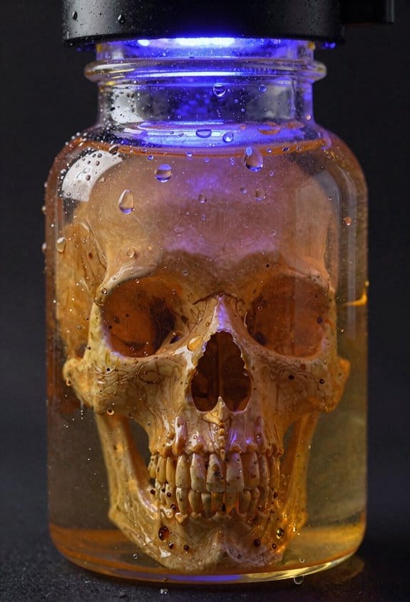
Before you decide whether to use a replica, photographs, or the original bone, know that your choice affects preservation, evidence handling, and what a jury will actually see.
If the skull is fragile, use a replica. Why it matters: you avoid damaging the original and keep the chain of custody intact. Example: a crumbling temporal bone with visible hairline fractures — printing a 1:1 replica lets you probe the fractures without risk. Steps:
- Assess fragility with a conservator or by using a simple drop test on a non-diagnostic area (no more than 1–2 mm displacement threshold).
- Choose printing scale (1:1 for courtroom fidelity, 1.5–2× if you need to magnify tiny trauma for jurors).
- Label the replica clearly with case ID and print date before transport.
If you’re planning destructive testing, use a replica or a sample instead of the original. Why it matters: you preserve the specimen for future review. Example: when radiocarbon or isotope sampling will remove cortical bone, cut and test a small, documented sample or use a printed model for demonstrations. Steps:
- Get written authorization for destructive tests from the legal custodian.
- Remove the smallest possible sample (often 5–10 mg for isotope work) and document with photos and CT slices.
- Keep the original specimen sealed and logged.
If you need quick reference or fine surface texture, use high-quality photographs. Why it matters: photos capture surface details that some prints may smooth out. Example: perimortem tool marks on a parietal bone — macro photos at 1:1 with raking light and a scale bar show striations clearly. Steps:
- Shoot RAW images at 1:1 with macro lens and raking light.
- Include a metric scale and color chart in every frame.
- Archive TIFF files and produce annotated JPEGs for reports.
If admissibility or chain of custody will be contested, prefer the original when handling won’t risk damage. Why it matters: judges may prefer originals for authenticity. Example: a skull presented in open-court demonstration where the defense disputes replication methods — transporting the original under documented chain-of-custody and handled only by authorized personnel reduces objections. Steps:
- Document every handler, time, and condition in a log.
- Package the specimen in padded, labeled containers with tamper-evident seals.
- Photograph and CT-scan the specimen pre- and post-transport.
Budget and time constraints often push you toward photos. Why it matters: they’re fast and cheap while still useful for many analyses. Example: a consultation request with a 48-hour turnaround — a set of high-resolution photos can let you form preliminary opinions. Steps:
- Prioritize required views (full vault, base, impacted areas).
- Deliver annotated images with measurements and scale.
- Note limitations explicitly in your report.
Ethics and documentation guide every choice. Why it matters: transparent records protect you and the evidence. Example: you chose to print a replica for a courtroom demo — document approvals, print parameters, material used, and who handled both replica and original. Steps:
- Get written approvals from the custodian and legal team.
- Record print files, printer settings, filament/resin type, and post-processing steps.
- Include all of that metadata with exhibits and in your report.
Quick checklist to decide, in order:
- Is the bone fragile or will testing be destructive? If yes → replica or sample.
- Will surface texture detail change the result? If yes → photographs.
- Will admissibility be contested and handling safe? If yes → original.
- Are time and budget tight? If yes → photographs first, replica if needed later.
Keep one rule firm: always label and log.
Recommended Products

Disarticulated Human Skull: The Axis Scientific 22-part disarticulated human skull model provides a hands-on learning experience to study the skull's major landmarks and anatomical details.
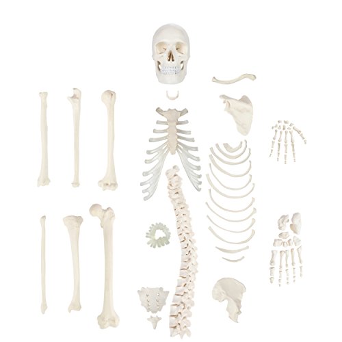
DISARTICULATED HALF SKELETON: The Axis Scientific Life-Size Disarticulated Half Human Skeleton with 3-Part Skull Model is a high-quality anatomical representation of human skeleton anatomy. This premium anatomical skeleton model offers an accurate study of the skeletal system anatomy for students and educators alike.
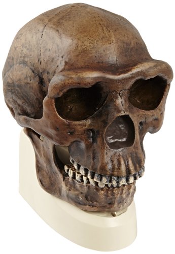
Sinanthropus anthropological skull model for study of early human cranial features
Scan-to-Print Workflow for Skull Reconstruction (Step-by-Step)
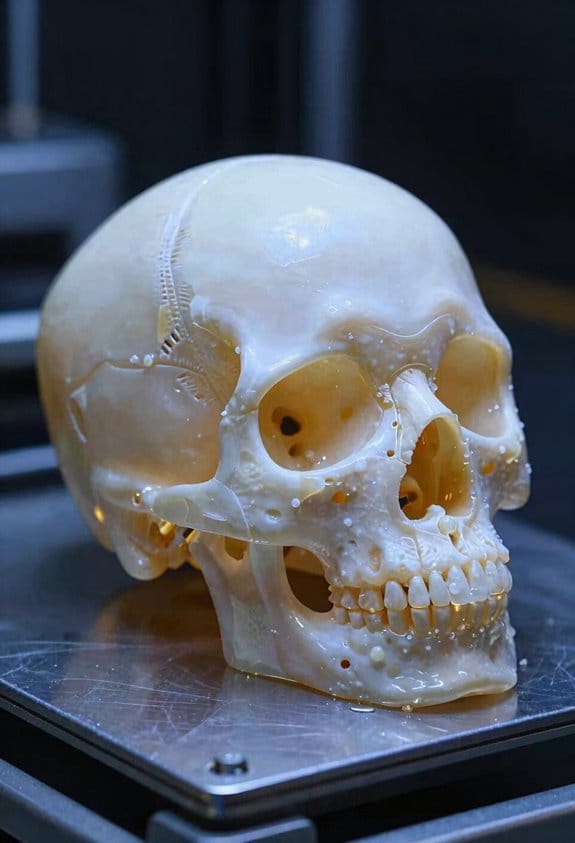
Before you start scanning, know why this matters: a clear plan preserves evidence and saves hours later.
Here’s what to do, step by step:
1) Secure and document the skull.
- Why: to preserve context for court and analysis.
- Example: Photograph the skull with a scale card and note GPS location, case number, and examiner name on a label placed beside the specimen.
- Steps:
- Place the skull on a non-reflective tray or foam cradle.
- Add a scale bar and a color chart in three photos: dorsal, ventral, and lateral.
- Write case details on a numbered tag and photograph the tag next to the skull.
– Tip: Use nitrile gloves and a marker that won’t touch bone. Keep chain-of-custody notes.
If you’ve ever tried handheld scanning without prep, this is why acquisition parameters matter: they determine whether you capture the small sutures or only a blur.
2) Choose and set up your scanner.
- Why: scanner choice and settings control resolution and legal defensibility.
- Example: For fine cranial sutures use a structured-light scanner at 50–100 micron resolution; for a quick overview use photogrammetry with 40–60% image overlap.
- Steps:
- Pick a non-contact scanner (structured-light, laser, or photogrammetry).
- Set resolution: 0.05–0.1 mm (50–100 µm) for forensic detail.
- For photogrammetry, shoot 40–80 photos around the skull with 50% overlap and consistent lighting.
– Tip: Calibrate the scanner per manufacturer instructions before each session.
Think of aligning scans like assembling a puzzle; if pieces are sloppy, the picture is wrong.
3) Perform the scan and create a merged mesh.
- Why: complete, well-aligned scans reduce reconstruction errors.
- Example: Scan the skull in three passes—top, base, and sides—then use fiducial markers to align the passes.
- Steps:
- Do at least three scan passes covering all aspects: dorsal, ventral, and lateral.
- Use markers or anatomical landmarks to aid alignment.
- Inspect each pass for holes, noise, and motion blur; re-scan any problematic areas immediately.
- Align and merge scans using your software’s mesh registration tools, aiming for RMS error <0.5 mm.
– Tip: Keep a log of scan files and timestamps for chain of custody.
Before you clean anything, understand why cleaning matters: removing noise prevents artifacts from changing measurements.
4) Clean and inspect the mesh.
- Why: cleaning removes stray points that can skew measurements or printing.
- Example: Remove floating points around the occipital area, then close a 2–5 mm hole with a conservative fill that keeps original curvature.
- Steps:
- Delete isolated points and spikes; use a 1–2 mm threshold for stray clusters.
- Smooth lightly—limit smoothing to one pass at low strength to preserve sutures.
- Fill holes smaller than 5 mm automatically; document any manual fills larger than 5 mm.
- Run a mesh check for non-manifold edges and inverted normals; fix until software reports zero critical errors.
– Tip: Save a versioned file before and after cleaning.
You don’t need fancy support tools if you orient the model correctly.
5) Prepare and slice for printing.
- Why: orientation and slice settings control support needs and surface fidelity.
- Example: Orient the skull so the maxilla faces down at 20–30° to reduce supports on facial details.
- Steps:
- Orient the model to minimize supports on diagnostic areas; aim for a 20–45° build angle depending on your printer.
- Choose layer height: 0.05–0.1 mm for SLA, 0.1–0.2 mm for FDM.
- Set infill: 10–20% for FDM or hollow with drain holes for SLA when allowed.
- Add supports sparingly and place them away from sutures and measurement landmarks.
- Slice and export G-code or printer file.
– Tip: Run a small test print of a critical region (e.g., orbital rim) before committing to the whole skull.
Before you accept the replica, verify it against originals because court will demand measurable fidelity.
6) Print, verify, and document.
- Why: verification proves the replica is a faithful physical record.
- Example: After printing, measure five linear distances (bizygomatic breadth, nasal height, etc.) on both skull and replica; differences should be <1–2% or <1 mm depending on case requirements.
- Steps:
- Post-process the print per material—wash and cure SLA or remove supports and sand FDM.
- Measure at least five predefined landmarks on original and replica; record differences.
- Photograph the replica with the same scale and chain-of-custody tag.
- Archive raw scan data, processed mesh, print files, photos, and measurement logs.
– Tip: Include a signed affidavit noting methods, equipment, and deviations.
Follow these steps in order, keep clear records, and you’ll produce a defensible replica that preserves both detail and chain of custody.
Recommended Products

REALISTIC SCANNING WITH HYBRID LIGHT SOURCE: Capture vibrant, high-resolution 3D data using a hybrid system of structured LED and handheld infrared light with EinScan H2 3D scanner for 3D printing. This handheld 3D scanner advanced imaging approach enhances texture accuracy and depth perception—ideal for facial scans or body scanner, intricate artwork, and textured objects. Experience realistic results without compromising performance.

The Next Level of 3D Scanning: Photorealistic Texture: 5MP Texture Camera, Capture rich, bright color and clean texture 3D model on a photorealistic level; Superior Environmental Adaptability: 3 VCSEL Projectors;

34 Cross Laser Lines: Easily and Quickly Scan Medium to Large Objects with reliable accuracy. Scanning a whole car in One Go.The laser array arrangement enables rapid and effortless capture of complete and accurate 3D data from medium to large objects
CT & Scanning Settings to Maximize 3D Printing Accuracy
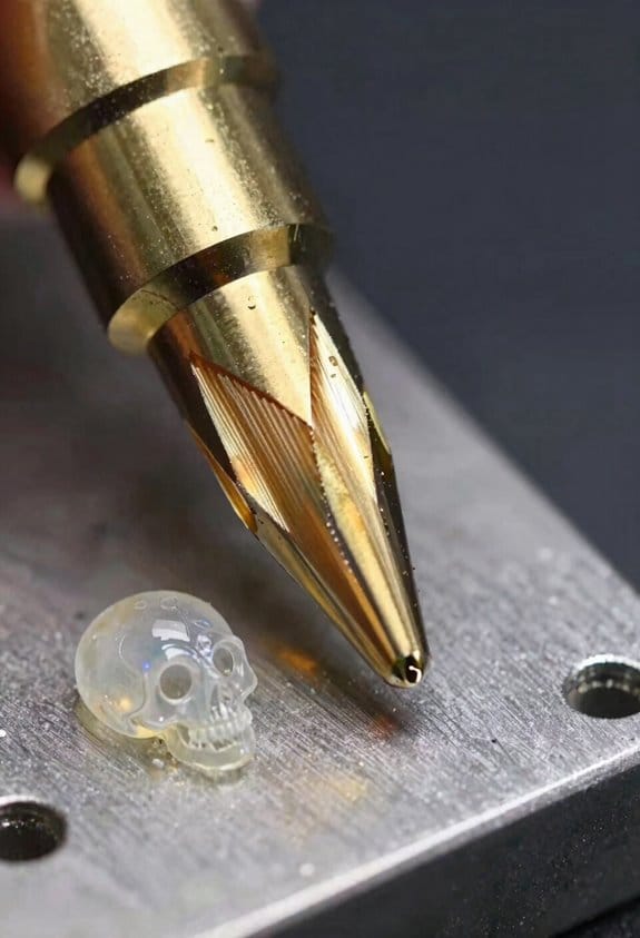
Before you set CT and scanner parameters, know this: small acquisition choices directly change how accurate your printed part will be.
How do I pick CT resolution and slice settings?
Why it matters: finer slices and smaller voxels capture small features and reduce errors in your final print.
1) Set slice thickness to 0.5–1.0 mm for standard forensic bone work; use 0.3–0.5 mm for tiny surface details like tool marks.
2) Aim for isotropic voxels (same x, y, z); if your in-plane resolution is 0.4 mm, make slice thickness ~0.4 mm.
3) Increase slice overlap by 30–50% (for example, 0.4 mm slice with 0.2 mm increment) when scanning curved or angled surfaces.
Real-world example: when scanning a fractured wrist, using 0.4 mm isotropic voxels with 50% overlap preserved thin cortical fragments that would have vanished at 1.5 mm.
What reconstruction filter should you use?
Why it matters: the filter decides if edges are sharpened or if noise is amplified, which changes segmentation boundaries.
1) Start with a high/standard sharpness or “bone” kernel for bone detail; if noise spikes, reduce to medium.
2) If you see grainy speckling that confuses segmentation, switch to a medium or soft kernel and increase mAs by 10–20% instead of keeping the sharp kernel.
3) Always record the kernel name and parameters in your export metadata.
Real-world example: I used a bone kernel on a skull CT and then switched to medium for the mastoid region to avoid false sutures created by noise.
How should you set acquisition technique (kVp, mAs, and calibration)?
Why it matters: correct kVp/mAs and calibration give consistent contrast and correct Hounsfield values for reliable thresholding.
1) Use 120 kVp for adult bone; drop to 100 kVp for small bones or pediatric cases to increase contrast.
2) Set mAs so noise index stays below the vendor’s recommended threshold; as a rule, increase mAs 10–30% if you switch from soft to sharp reconstruction.
3) Run the scanner’s daily or weekly phantom calibration and log the results before major scans.
Real-world example: scanning a mandible at 100 kVp, 200 mAs produced clearer cortical borders than 120 kVp with low mAs, which helped segmentation.
How do I handle surface scanning for 3D printing?
Why it matters: capture geometry and avoid holes or artifacts that need manual cleanup.
1) Keep the scanner 20–40 cm from the object for handheld structured-light systems (check your device manual).
2) Scan at ~45° angles on concave areas and do at least three passes from different directions for complex geometry.
3) For textureless or shiny surfaces, apply a removable matte spray and include scale markers in the frame.
Real-world example: scanning a prosthetic skull: three passes at 45° and a light matte spray removed specular reflections and eliminated holes near the orbital rim.
What export and verification steps should you follow before segmentation?
Why it matters: consistent, well-documented input prevents surprises during segmentation and printing.
1) Export DICOM with full header; for surface scans export OBJ or STL plus a PLY with color if available.
2) Verify voxel size in the DICOM header matches your planned slice thickness and in-plane resolution.
3) Check calibration logs, kernel name, kVp/mAs, and write them into a single scan record you keep with the model.
Real-world example: I caught a mismatch once where DICOM listed 0.25 mm voxels but the scanner used 0.5 mm slices; fixing the acquisition prevented a ruined print.
Quick checklist before you start segmentation
Why it matters: this short list saves time and prevents preventable errors.
1) Confirm isotropic voxel size. 2) Note reconstruction kernel. 3) Verify kVp/mAs and calibration log. 4) Ensure export formats include DICOM and STL/OBJ/PLY as needed.
Do this every time.
If you follow these steps, your scans will give you cleaner segmentations and fewer surprises in the print.
Recommended Products

SIMPLE, ONE TOUCH SCANNING. Press one button and documents are scanned, cleaned up, and organized. QUICK MENU lets you quickly scan-drag-drop to your favorite computer apps

MANAGE HOME AND SMALL BUSINESS DOCUMENTS WITH EASE. Large color touchscreen; fast 40ppm duplex scanning; Wi-Fi and USB connectivity; photo scanning; and support for a wide variety of cloud services
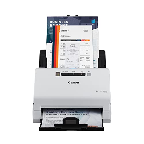
Utilize the included software to quickly scan batches of receipts and invoices to extract contents such as payee, amount, date, etc., and automatically upload information directly to Intuit QuickBooks Online or another third-party cloud service.
Forensic Printer & Material Choices for Courtroom-Ready Models
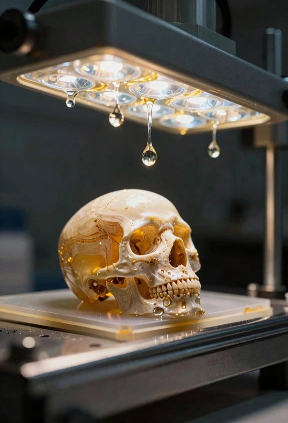
Before you pick printers and materials, know why it matters: courtroom evidence must be defensible and stable over time.
Pick printers with documented certification and published test data so you can cite numbers under cross-examination. Example: a Forensic Imaging Lab used a Formlabs Form 3B (SLA) with the manufacturer’s resolution spec (25–100 µm) and vendor test reports to justify accuracy in a skull-suture case. Steps:
- Ask the vendor for certification documents and print-repeatability data.
- Record the model, serial number, firmware version, and certificate reference.
- Archive the vendor test PDFs alongside your case file.
Match the technology to the detail level and use-case, because different methods preserve different features. If you need hairline cranial sutures and fine surface texture, use SLA or high-resolution DLP at 25–50 µm layer height; if you need a handleable, tough prop for courtroom demonstrations, use FFF with PETG printed at 0.2 mm layer height and 4–6 perimeters. Real example: a prosecutor displayed a PETG replica that survived repeated handling without edge chipping. Steps:
- Decide required feature size (e.g., sutures <0.5 mm).
- Choose tech that meets that resolution (SLA/DLP for <0.5 mm; FFF for >0.5 mm).
- Set layer height and perimeter/infill based on durability needs.
Consider material aging because prints can change color or shrink, and jurors may see the model months or years later. Example: UV-exposed PLA can yellow within 6–12 months on a window sill, changing perceived coloration. Steps:
- Run accelerated-aging tests: 100 hours UV exposure and 30°C humidity cycling for samples.
- Measure and photograph dimensional change to ±0.1 mm.
- Choose materials with documented long-term stability (medical-grade resins or UV-stable PETG).
Control post-processing and orientation so replicas are reproducible and defensible. A consistent workflow reduces variability between prints. Example: one lab found that orienting skulls with the occipital bone down and using identical support patterns cut post-process fit variance from 0.8 mm to 0.2 mm. Steps:
- Fix print orientation and support strategy in writing.
- Use the same post-cure times, solvent rinses, and sanding sequence each time.
- Document orientation screenshots and slicer/export settings.
Keep traceable records of every setting and material; provenance strengthens your evidentiary chain. Example: a defense challenge was dismissed after the lab produced a print log showing temperature, resin batch, and post-cure lamp hours. Steps:
- Log printer settings, material batch numbers, and operator initials for every print.
- Store photos of the print at key stages: raw, post-wash, post-cure, and final.
- Keep samples of the printed material and a labeled coupon with case ID.
Follow these concrete actions and you’ll create replicas that hold up under scrutiny and remain useful over time.
Recommended Products

Designed for Zero-Basic Newbies: Creality Halot R6, a resin 3d printer designed for newbies, is easy to operate, it has a built-in boot guide to help you complete the networking and other basic configurations can be a complete novice can be used right out of the box

Upload your 3D file Via Amazon message.
Validating Accuracy : Expected Errors, Reliability, and Reporting
If you’ve ever handled a 3D-printed forensic replica, this is why validating it matters: courts and investigators need to know how close your print is to the original so evidence isn’t misread.
Why this matters: you need numbers to show how much your replica might differ from the real anatomy. For example, compare a skull print to the CT scan and note that mean differences are often 0.2–1.2 mm for consumer workflows — that range tells a judge what to expect.
How to check expected errors (one real example):
- Scan your original with the same device you used to create the model; for instance, use a clinical CT at 0.5 mm slice thickness for a bone specimen.
- Align the scan and the print’s scan in software (rigid registration).
- Compute point-to-point distances and report the mean, standard deviation, and the full range (e.g., mean 0.6 mm, SD 0.3 mm, range 0.0–2.4 mm).
- Include a visual color map showing hotspots where errors exceed 1.5 mm.
This example shows you’ll typically find sub-millimeter averages but occasional outliers up to a few millimeters.
How to document measurement uncertainty and why it matters: you must show what caused variation so others can evaluate reliability. For example, list scanner slice thickness (0.5 mm), reconstruction filter (bone/sharp), mesh decimation (percentage removed), and printer layer height (e.g., 0.1–0.2 mm). Then state how each contributes to error; a 0.5 mm CT slice can introduce up to ~0.25 mm axial uncertainty, and a 0.2 mm printer layer can add stair-step artifacts at steep slopes.
How to demonstrate reliability (real example):
- Repeat scans: scan the same object three times and report variability.
- Intraobserver checks: have the same operator segment twice, blind to the first result, and report differences.
- Quantitative fit tests: perform a best-fit alignment and compute root-mean-square error (RMS).
Example result: three CTs produced RMS 0.55, 0.60, 0.58 mm, so your workflow is stable within ~0.05 mm.
How to report results so courts and users can judge the evidence: be explicit and concise. Use a short table or bullet summary stating methods, sample sizes, mean error, SD, range, and limitations. For instance: Scanner: CT 0.5 mm; Segmentation: threshold + manual clean; Printer: SLA, 100 μm layer; Mean error: 0.6 mm; Range: 0–2.4 mm; Limitation: poor detail below 0.5 mm. This gives a clear, actionable snapshot.
Practical recommendation: when anatomy must be precise, use high-resolution CT and an SLA printer with 50–100 μm layers; expect mean errors under 0.5 mm in good conditions. If you can’t get that, state the limitation and show the color maps and numeric ranges so users know where the replica is less reliable.
Reproducing Fragile Crime-Scene Evidence: Best Practices & Examples
Before you reproduce fragile evidence, you need to know why it matters: you want to let examiners handle a copy so the original doesn’t get any more wear.
Here’s how you’ll preserve custody and document everything.
- Scan log: write the item ID, who scanned it (name and badge number), date and time, scanner model, and file name.
- Handling log: list every person who touched the original, with timestamps and reason for access.
- Print log: record print date, printer model, filament/resin type, and print ID.
Example: at a burglary scene, you log that Officer Lee (Badge 214) scanned a broken window pane with a Artec Space Spider at 10:15, saved file WindowPane_214_0312.obj, and printed Replica_WP_214_01 on a Formlabs Form 3 using Grey Resin V4.
You should capture surface detail at high resolution because small features matter for comparison.
- Scanning settings: use at least 0.1 mm point spacing (100 microns) and 0.2 mm capture depth; if the feature is tiny, go to 50 microns.
- Calibration: run a manufacturer calibration target before scanning and save that file.
- File formats: export a lossless mesh (.stl or .ply) plus a textured .obj if color matters.
Example: a toolmark on a doorframe was scanned at 50 microns with a GOM ATOS; the mesh retained crisp gouge edges that were invisible in photos.
Pick printing materials and settings that match stiffness so you don’t change impressions when someone touches the replica.
- Material choice: for hard ceramics or glass use a rigid resin (Shore D 70+); for soft plastics or rubbery materials use a TPU filament with 85A shore.
- Layer height: print at 50–100 microns for visible features; for enlargements you can go to 200 microns.
- Orientation and supports: orient the print to minimize layer lines across critical features, and use soluble supports where they might abrade detail.
Example: to mimic a brittle shell fragment, you printed at 50 microns in a rigid resin and oriented the shard so fracture edges fell on the XY plane to keep them sharp.
Label and isolate originals and replicas so comparisons don’t introduce confusion.
- Labeling: mark replicas clearly with “Replica” plus print ID and date, using an indelible label or engraved tag.
- Storage: keep originals in sealed evidence bags or foam-lined boxes and store replicas separately in labeled totes.
- Access control: require sign-in for anyone who moves an item; keep copies of chain-of-custody logs with both original and replica.
Example: you attach a small engraved aluminum tag reading “Replica_WP_214_01 — 2026-03-12” and place the original window fragment in a sealed evidence bag with a tamper-evident sticker.
Create scaled enlargements and record processing metadata so others can judge fidelity and repeat your workflow.
- Scaling: enlarge tiny marks by 2–10x when printing so examiners can see microscratches without a microscope.
- Metadata: include scanner settings, calibration files, software versions, mesh decimation percentage, smoothing operations, and printer slicer settings in a single PDF attached to the print.
- Validation: where possible, scan the printed replica and compare it to the original mesh; record RMS deviation (aim for <0.2 mm for forensic replicas).
Example: you printed a 5x enlargement of a 1 mm tool nick, saved the slicer profile (0.05 mm layer, 20% infill, 45° orientation), then rescanned the replica and reported an RMS error of 0.12 mm.
Follow these concrete steps and you’ll let others examine fragile evidence without putting the original at risk.
Recommended Products

➤【Four in one multifunctional scanning】 - combining 34 cross lines (fast), 7 parallel lines (detailed), 1 single line (deep hole) blue laser and NIR structured light (unmarked), suitable for any project.

Complete Measurement Solution: The CMM Edition is a professional kit designed for industrial inspection. It includes the MetroY Ultra scanner, a metrology-grade carbon fiber ball plate for on-site verification, and a 1-year license for the Revo Measure metrology software, enabling a closed-loop workflow from scanning to certified reporting. (Note: Revo Measure only supports Windows 10/11. Check compatibility before buying.)
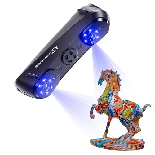
All-in-One Scanning from Micro Details to Massive Objects: Capture everything from tiny jewelry and dental models to full automotive parts and large architectural structures with one powerful scanner. With an ultra-wide scanning range from 5 mm to 4000 mm, users no longer need multiple devices for different projects — reducing equipment costs while expanding workflow flexibility for prototyping, engineering, restoration, and large-scale design work.
Presenting 3D Exhibits in Court: Admissibility, Documentation, Tips
Before you present a 3D-printed exhibit, know it matters because judges focus on how the model was made as much as what it shows. If you don’t show the process, the court may exclude the replica.
1) How do you document chain of custody?
Why it matters: courts need a clear record to trust evidence.
Steps:
- Record who scanned the object, with full name, role, and contact.
- Log the exact date and time for each action: scan, file processing, slicing, and print start/finish (use ISO format like 2026-03-21T14:32:00).
- Keep file versions and file hashes (SHA-256) for each version, and note software and version numbers.
- Photograph the object before scanning, the scanner in use, and the printed part with a timestamped camera.
Example: For a snapped bolt from a machine, you record that Jane Doe scanned it on 2026-02-10 at 09:12:00 using Artec Eva v3.8, saved file bolt_v1.stl (SHA-256: abc123…), processed to bolt_v2.stl on 2026-02-11 at 11:05:00, and printed on a Form 3 at 2026-02-12 with a 50 µm layer height.
2) What labels and visuals should you prepare?
Why it matters: clear visuals let the jury judge scale and limits accurately.
Steps:
- Add a printed label on the exhibit stand: case number, exhibit number, date, and preparer name.
- Include a visible scale bar on the base with metric units and a ruler photo at 1:1 scale next to the model.
- Prepare a one-page, non-technical summary of methods and limitations (max 200 words).
Example: For a 3D replica of a skull fragment, include a 10 cm scale bar glued to the base, a label “Exhibit 12 — Skull Fragment — Prepared by Dr. Lee — 2026-03-01,” and a one-page summary noting scanner resolution (0.2 mm), smoothing applied, and estimated dimensional accuracy (±0.3 mm).
3) How do you explain accuracy in testimony?
Why it matters: you give the court a way to evaluate trustworthiness.
Steps:
- State scanner resolution and measured point accuracy (e.g., 0.2 mm resolution, ±0.25 mm accuracy).
- State printer tolerances and print settings (printer model, material, layer height, infill, and orientation).
- Compare key dimensions of the replica to the original using measured values and differences.
- Offer source files and processing logs for in-camera review.
Example: You testify: “I used a Leica ScanStation P40 with 0.1 mm resolution; the printed part was made on an Ultimaker S5 at 0.1 mm layer height. A 50 mm notch measured 50.3 mm on the replica, so the error is +0.3 mm, within our ±0.5 mm threshold.”
4) What do you bring for potential challenges?
Why it matters: challengers often go after gaps, not the main evidence.
Steps:
- Bring originals or high-resolution photographs of the original object.
- Bring the raw scan files, processed files, G-code/print files, and logs on a read-only medium.
- Bring print material certificates and calibration records for the printer used.
- Bring a short checklist of processes followed, signed and dated.
Example: For a bicycle frame part, you bring scan_raw.ply, frame_v1.stl, frame_final.gcode on a USB marked “read-only,” the filament spec sheet showing tensile strength, and the printer’s last calibration report dated two days before printing.
5) Practical courtroom tips
Why it matters: small details keep your exhibit admissible and persuasive.
Steps:
- Test setup: rehearse how you’ll enter, carry, and place the exhibit; make a damage-proof carrying case.
- Demonstrate scale: show a ruler photo, then place the replica next to the original or a known object for the jury.
- Keep explanations brief: provide a single-sheet summary for the judge and one for the jury with plain language.
- Use an expert who can state methods and numbers confidently; avoid vague claims.
Example: Before trial, you rehearse a 90-second demo where you place the model on the stand, point to the 10 cm scale bar, and hand the judge the one-page summary.
Final note: keep every record dated, every file hashed, and every measurement noted with units; those concrete details win admissibility.
Gaps, Risks & Standards Forensic Teams Must Plan For
Before you use 3D-printed models in court, you need to know one clear thing: if you skip planning now, the evidence could be rejected.
Here’s what actually happens when you print from CT or photogrammetry: minute errors in imaging and printing become visible as millimetre-level differences in the model. For example, a skull printed from a 0.6 mm CT slice can show a 1–3 mm deviation on the nasal bone compared with the original, which a defense expert might highlight. You should always request the highest CT resolution available (≤0.5 mm slice thickness) and record the scanner model, acquisition settings, and reconstruction kernel.
Why this matters: printer materials and processes change how features look and feel. Labs often assume a resin or PLA print is accurate, but many materials haven’t been validated for dimensional stability. A practical step: run material validation tests before casework using a calibration object with known distances (e.g., a gauge block set), print it, and measure differences; document results for court.
You must preserve chain integrity because courts require an auditable trail. Start by numbering and photographing every transfer. Example: when a scan leaves radiology, take a photo of the storage device, log the time and person, and sign a printed chain-of-custody form. Steps to follow:
- Label digital files with case ID, date, and operator.
- Hash original DICOM and store the checksum in your case file.
- Record each file transfer, who did it, and why.
Before you process files, know that segmentation choices change outcomes; that’s why interobserver checks reduce error. Do this with an example: three technicians segment the same femur CT and you compare landmark distances — if two or more differ by more than 2 mm, redo segmentation. Steps:
- Have two independent segmentations for metric cases.
- Use predefined threshold settings; list them in the report.
- Quantify observer variance in the case file.
Think of ethical considerations like handling a fragile artifact: you must respect privacy and remains. Explain one concrete action: blur identifying facial features on demonstration prints used for public outreach, and store the unblurred model only under restricted access. If the family objects, document the objection and seek counsel.
You need conservative reporting because overclaiming damages credibility. Tell jurors what the model can and cannot show in plain terms, then back it up with numbers. Example language you can use in a report: “Measured landmark A–B on original CT = 45.2 mm (±0.8 mm); on print = 45.9 mm; total difference = 0.7 mm.” That shows transparency.
Adopt standardized protocols and validate workflows so your methods hold up in court. One practical protocol:
- Scan with ≤0.5 mm slices and document settings.
- Store DICOMs with checksum and restricted access.
- Perform two independent segmentations and report variance.
- Validate printer/material with calibration prints monthly.
- Keep a signed chain-of-custody for every transfer.
Training and metadata reduce risk because they create repeatability. Example training: run monthly exercises where staff print a standard test object, measure it, and log results; post the pass/fail metric on a lab board. For metadata, include scanner, slice thickness, software version, segmentation settings, printer model, material lot number, and operator initials with dates.
Push for specialist working groups because standards are still evolving; one lab’s test can become a community protocol. Contribute your validation data to a regional group, and use their recommended acceptance thresholds — for instance, ≤1 mm mean deviation for metric templates.
Finally, document every decision, keep reporting conservative, and get legal review before using prints in court. A single signed validation report and chain-of-custody log often makes the difference between admissible and excluded evidence.
Frequently Asked Questions
Can 3d-Printed Replicas Be Used to Extract DNA or Biological Evidence?
No — I wouldn’t rely on 3D-printed replicas to extract DNA; contamination risk is high and material compatibility with extraction methods is poor, so originals or properly validated sampling from remains remain necessary for reliable results.
How Do Copyright or Ownership Issues Affect Scanning Remains?
I’d note a 12.0% max model variance as context: ownership disputes and cultural patrimony claims can block scanning, require consent or legal transfer, and I’d recommend documented permissions and stakeholder engagement to avoid litigation.
What Are Ethical Considerations for Reconstructing Identifiable Faces?
I think ethical considerations include privacy risks and strict consent requirements: I’d make certain identifiable reconstructions respect family wishes, anonymize when possible, obtain informed consent or legal authorization, and balance investigation needs against dignity and harm prevention.
Can Defense Teams Independently Reprint Prosecution-Provided Models?
“Measure twice, cut once.” I can; defense teams often pursue independent verification by performing defense replication of prosecution models, but they should document methods, use high‑resolution scans, and comply with court rules to challenge accuracy and admissibility.
How Are Court Chains of Custody Maintained for Digital Files?
I make certain court chains of custody for digital files by generating file hashes, keeping immutable access logs, using controlled transfers with signatures, and documenting every handover so you’ll see who accessed or altered evidence and when.