As an Amazon Associate, we earn from qualifying purchases. Some links on this site are affiliate links at no extra cost to you. Our recommendations are based on thorough research and editorial judgment.

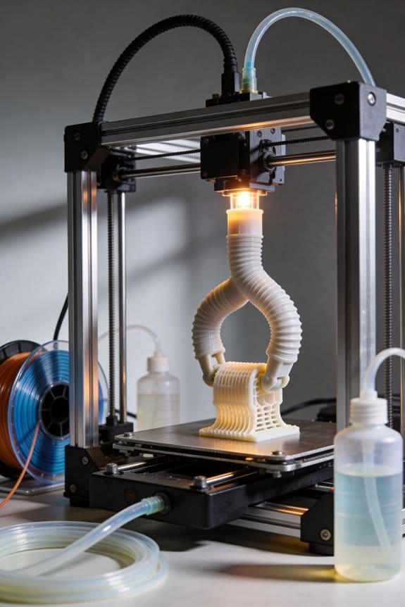
Reverse Engineering Antiquities: Restoring Historical Artifacts With 3D Scanning
You’ve just unwrapped a fragile pottery shard and paused, unsure how to capture every curved flaw without risking further damage. You need to know exactly which scanner settings and handling steps will preserve the piece while producing accurate digital data for reconstruction. Most people rush to a single consumer scanner or over-handle objects, creating noisy scans and irreversible stress on artifacts. This piece shows, step by step, how to choose the right scanner by size and resolution, calibrate and test scans, and process meshes so you can identify tolerances and make reversible repairs.
It also explains safe handling, backup protocols, and printable assembly methods for faithful replicas. It’s easier than it looks.
Key Takeaways
Section 1 — Which scanner should you use?
Before explaining how, know this matters because capturing detail without touching the object prevents irreversible damage.
If you’ve ever picked up a pottery shard and felt the surface flake, you’ll see why non‑contact capture is critical.
Use a structured‑light or blue‑laser scanner set to 0.05–0.5 mm resolution depending on detail needs. Short sentence.
Example: scanning a 10 cm carved amulet, set 0.05–0.1 mm for fine inscriptions; for a 30 cm statue, 0.2–0.5 mm works.
1) Choose structured‑light for matte surfaces and fine texture; choose blue‑laser for glossy or small reflective inlays.
2) For fragile ceramics, aim for 0.05–0.1 mm.
3) For larger stone fragments, 0.3–0.5 mm is fine.
Section 2 — How do you prepare fragile artifacts?
Before explaining how, understand this prevents handling damage and keeps pieces stable during capture.
Think of artifact support like a dental mold holding a tooth steady.
Use soft foam, silicone pads, and mark fragile zones with removable tags. Short sentence.
Example: for a broken Roman bowl, cut polyethylene foam to cradle the rim, add silicone gel pads under the base, and attach small flagged paper markers to cracked edges.
1) Lay down a 5–10 mm closed‑cell foam base.
2) Add 2–3 mm silicone gel pads beneath contact points.
3) Mark fragile spots with numbered removable tags for reference.
Section 3 — How should you run the scan session?
Before explaining how, know this ensures complete, aligned data and reduces rescans.
Here’s what actually happens when you scan without planning: you miss parts and waste hours.
Calibrate the scanner before each session, run a quick 60‑second test scan to check settings, and capture overlapping passes with 30–50% overlap. Short sentence.
Example: on a statuette, do a base pass (0°–90°), flip and do a second pass (90°–180°), then add two orthogonal passes for undercuts.
1) Run the device calibration routine at the start.
2) Perform a 60‑second test scan and inspect edges.
3) Capture full‑coverage passes with 30–50% overlap and vary angles for undercuts.
Section 4 — How should you store and track scan data?
Before explaining how, realize traceability saves time and prevents data loss later.
The difference between findable and lost files comes down to naming and backups.
Save raw scans and processed meshes to two separate physical or cloud locations and record metadata (scanner, settings, date, operator). Short sentence.
Example: name files like “ROM_Bowl_20260315_ScannerA_0.1mm_raw.ply” and keep a CSV metadata log with camera settings and notes on fragile zones.
1) Use a filename convention: [Site]_[ArtifactID]_[YYYYMMDD]_[Scanner]_[Res]_[stage].
2) Back up to local RAID and a cloud bucket.
3) Log metadata in a spreadsheet or database.
Section 5 — How do you produce restorable meshes?
Before explaining how, remember that a quick mesh helps you find missing areas and plan repairs.
The fastest way to find holes is to make a low‑decimation mesh first.
Generate a low‑decimation mesh to locate holes, then apply ICP alignment, targeted rescans, and appropriate hole‑filling for restoration. Short sentence.
Example: create a 200k–500k face mesh from scans, use ICP to align passes, then rescan any holes and fill gaps with constrained Poisson or manual retopology for visible surfaces.
1) Create a low‑decimation mesh (200k–500k faces) to inspect coverage.
2) Run ICP alignment between passes.
3) Targeted rescan missing zones, then use hole‑filling: constrained Poisson for small unseen cavities, manual retopo for visible features.
Final practical tip
Before explaining how, accept that small habits avoid big problems later.
It sounds obvious, but testing and metadata will save you days when someone asks for provenance.
Keep a one‑page checklist (calibrate, test scan, support, overlap, save, backup). Short sentence.
Example: tape a laminated checklist to your scan table with boxes for calibration time, test scan OK, and backup completed.
1) Use the checklist every session.
2) Archive one PDF of the session with raw files, meshes, and the metadata CSV.
Quick Scan-to-Repair Checklist: 6 Steps to Start
Before you start scanning, know why prep matters: it prevents wasted scans and damaged parts. Start by gathering tools and making a clear plan so your scan-to-repair workflow is reliable and fast.
1) What safety checks should you run first?
Why it matters: safety prevents broken parts and injury.
Steps:
1. Inspect the object for fragile spots and mark them with painter’s tape.
Example: a cracked ceramic flange—mark all hairline fractures and tape a 50 mm buffer.
2. Identify where supports are needed and place foam blocks or adjustable stands every 200–300 mm under overhangs.
Example: a dented car bumper—shim supports under the lowest three points.
3. Set non-contact safe distances: for structured-light scanners keep 300–500 mm, for laser scanners keep 100–400 mm.
Example: handheld structured-light scan of a helmet—hold 400 mm away.
4. Confirm power and lighting: bring two battery packs and one portable LED panel at 5,000–6,000 K.
Example: field scan in a garage—use a 20,000 mAh battery and one 50 W LED.
2) How do you choose scanning parameters?
Why it matters: the right settings capture detail without creating huge files.
Steps:
1. Pick resolution based on target detail: 0.5–1.0 mm for general geometry, 0.05–0.2 mm for edges or threads.
Example: scanning a brake rotor—use 0.1 mm for the rotor face and 0.8 mm for the hub.
2. Set range to cover the object with 10–20% overlap between captures.
Example: scanning a motorcycle tank—scan each side with 15% overlap.
3. Limit file size: target 200–500 MB per raw scan file; increase only if fine detail needs it.
3) What should you do in a test scan?
Why it matters: a quick trial finds alignment and shadow problems before you commit time.
Steps:
1. Do a 1–2 minute scan of a representative area and check alignment markers and coverage.
Example: test-scan a corner of a window frame to verify edge capture.
2. Adjust scanner position and tilt to remove occlusion; move by 50–100 mm increments if needed.
Example: a statue with an arm blocking light—step 75 mm to the left.
3. Re-run the short scan until you get clean alignment and no big shadowed zones.
4) How do you back up raw data?
Why it matters: backups keep your work traceable and safe from loss.
Steps:
1. Save raw files to two separate locations immediately: one external SSD and one cloud folder.
Example: copy the SD card to a 1 TB SSD and upload to a Google Drive project folder.
2. Document metadata: date, scanner model, resolution, range, operator name, and scan IDs.
Example: filename convention: Project_Device_Res_mm_Date_Operator (e.g., TankX_LS0.1_20260321_Amy).
5) How and when do you process preliminary meshes?
Why it matters: early processing reveals gaps so you can plan targeted rescans.
Steps:
1. Generate quick meshes at low decimation (30–50% quality) to inspect for holes and alignment errors.
Example: create a 30% decimated mesh of an engine cover to find missing bolt holes.
2. Inspect using measurements: check three critical dimensions against caliper readings.
Example: measure bolt circle diameter and compare to a caliper: accept if within ±0.2 mm.
3. Plan targeted rescans for any gaps or features that failed the checks; note exact scan angles and distances needed.
6) When do you begin repair work?
Why it matters: repairs only work if your data is verified and repeatable.
Steps:
1. Confirm you have: two backups, documented metadata, at least one processed mesh, and a list of targeted rescan areas.
Example: before welding a crack, ensure the mesh shows the crack ends within ±0.5 mm.
2. If anything’s off, do the targeted rescan, update backups, and reprocess the mesh.
Follow these steps and you’ll avoid surprises during repair.
Recommended Products

ULTRA-BRIGHT 6500LM ILLUMINATION:This LED ceiling light delivers powerful, even lighting to replace outdated fluorescent fixtures. Ideal as a ceiling light fixture for offices, homes, and garage lights ceiling LED applications.
【High Output, Ultra Bright 5600K Color Temperature】High output lighting for interviews, studios, live streaming, video conferencing, and more! 96+ CRI and TLCI means you get the highest quality light output with excellent white color rendition and no green or pink tint. Excellent for YouTube, Zoom, and on-location lighting where bright, high-output lighting is essential.

【Flexible, Foldable & Linkable Design】The GVM B100C folds in half and links seamlessly with multiple units for wide-area or custom illumination. Its flexible light mat design delivers soft, even light that reduces harsh edges, ideal for product photography, portraits, tight corners, or irregular props. Tool-free setup enables fast installation for studio, on-location filming, and creative content production.
Prioritize What to Scan: Artifact & Feature Criteria

Before you start scanning, know why this matters: you can’t capture what you’ll need later if you try to scan everything at once.
Think of artifacts and features like surgical triage — prioritize the ones that affect diagnosis and treatment. Start by ranking items using three concrete criteria: historical value (assign 1–5), current condition (1–5), and likelihood of future change (1–5). Example: a 19th-century carved door with original paint might score 5, 4, 5 and get top priority.
Why this step matters: you’ll save time and storage by focusing on what’s irreplaceable. For example, on a church restoration I worked on, scanning the original pew ends first captured hand-tool marks that were gone after ten years; that single scan guided the whole repair.
How to pick what to scan first:
- List every artifact and feature in the area you’re documenting.
- For each item, give three scores (historical value, condition, change risk).
- Multiply the three scores to get a priority number and sort from highest to lowest.
Do that for 20–50 items in one session.
You should favor things with high contextual significance because they tell stories you can’t recreate later. Pick items tied to a known event, maker, or unique construction detail. Example: a beam with a carved mason’s mark told us which workshop built the barn, so we photographed and did a 0.5 mm LIDAR scan first.
Why condition matters: unstable materials can disappear between inspections. If an object is physically fragile, wet, salt-damaged, or biologically active, it needs non-contact or rapid capture. For instance, damp paper labels on crates lost legibility within months; capturing them with raking light and 600 dpi scans preserved the handwriting.
How to handle unstable or fragile pieces:
- Flag items that are wet, flaking, or salt-crusted.
- Use non-contact methods first: photogrammetry at 70% overlap or LIDAR from 1–3 meters.
- If you must touch, follow conservator guidance and document every handling.
Do this for each fragile item before anything else in the area.
Prioritize active decay and areas showing change because repeat documentation supports restoration planning. Example: a roof truss with active insect galleries was re-scanned every six months to measure loss; those scans quantified material loss and informed treatment timelines.
How to stage your scans for efficiency:
- Do a coarse scan to map the whole object or space (lower resolution, faster).
- Identify complex areas or details from that coarse scan.
- Re-scan those complex zones at high resolution or with specialized lighting.
This staged method cuts file size and focuses detail where it matters.
You also want distinctive features that define form or function — corners, joins, tool marks, and fittings. Capture the overall geometry, then zoom into junctions at 0.1–0.5 mm resolution if your equipment allows. Example: the hinge mortise on a historic chest defined how the lid operated, so we recorded the full chest with handheld LIDAR, then did close-up photogrammetry of the hinge at 2 mm increments.
Final practical checklist you can use right now:
- Make the list and score each item (1–5 each).
- Multiply scores and sort by highest priority.
- Flag fragile and actively decaying items for immediate non-contact capture.
- Do a coarse whole-object scan, then targeted high-detail scans.
- Log methods, distances, resolutions, and lighting for each capture.
Save your priority list with the scans so restoration teams know why you chose each target.
Recommended Products

➤【Four in one multifunctional scanning】 - combining 34 cross lines (fast), 7 parallel lines (detailed), 1 single line (deep hole) blue laser and NIR structured light (unmarked), suitable for any project.

REALISTIC SCANNING WITH HYBRID LIGHT SOURCE: Capture vibrant, high-resolution 3D data using a hybrid system of structured LED and handheld infrared light with EinScan H2 3D scanner for 3D printing. This handheld 3D scanner advanced imaging approach enhances texture accuracy and depth perception—ideal for facial scans or body scanner, intricate artwork, and textured objects. Experience realistic results without compromising performance.

➤【High-Precision Dual-Technology Scanning】-Master any scanning challenge with dual-engine precision. The Sermoon P1 combines Blue Laser and Infrared technologies for maximum versatility. Choose from three professional modes: Deep Hole Scan (Single Line) for cavities, Detail Scan (7 Lines) for complex surfaces, and High-Speed Scan (22 Lines) for large objects. Achieve ultra-detailed 0.02mm accuracy with Blue Laser for mechanical parts, prototypes, and artifacts. Switch safely to Infrared for fast, marker-free scanning of faces, bodies, sculptures, and cultural relics.
Choosing a 3D Scanner and Settings for Accuracy

Before you choose a scanner, know why accuracy, speed, and conservation matter: the wrong choice can waste time and damage a fragile item.
1) Which scanner type for what size?
Why this matters: picking the right scanner saves time and preserves detail.
Example: scanning a 10 cm carved ivory pendant vs. a 2 m wooden statue.
Steps:
- For items under 30 cm, use a handheld structured-light or blue‑laser scanner; set resolution to 50–200 microns for medium detail and 20–50 microns for very fine detail.
- For items 30–200 cm, use a tripod-mounted structured‑light system or a medium-range laser scanner; aim for 200–500 microns.
- For items over 2 m, use a terrestrial LiDAR unit; expect 1–10 mm accuracy depending on range.
Tip: if you need sub-20 micron detail for small artifacts, consider a desktop micro‑CT instead.
2) How to check and maintain sensor calibration?
Why this matters: an uncalibrated sensor drifts and gives wrong measurements.
Example: you scan a bronze coin, only to find edges softened by calibration error.
Steps:
- Perform a calibration check at the start of each day and after any bump.
- Use a manufacturer calibration target or a certified gauge block; record measured vs. nominal values.
- If error exceeds the spec (commonly 0.05–0.1% of range), recalibrate immediately.
Record calibration date and measured deviation in your session notes.
3) How to set scan spacing and sampling?
Why this matters: spacing controls captured detail and file size.
Example: ornate filigree on a silver cup requires much denser sampling than a smooth shield.
Steps:
- Measure the smallest feature you need to capture in millimeters.
- Set point spacing to roughly half that size (e.g., 0.5 mm feature → 0.25 mm spacing).
- For general surfaces with low detail, use 2–5 mm spacing to speed capture.
4) How to adjust frame rate and exposure for fragile materials?
Why this matters: too much light or long exposure can harm sensitive surfaces.
Example: scanned a faded textile that light exposure loosened; you want to limit contact and light.
Steps:
- Reduce exposure time and lower frame rate to the minimum that still produces clean frames—start at 15–30 fps and adjust down if needed.
- Use neutral-density filters or lower projector intensity if using structured light; try a 30–50% intensity reduction.
- Limit total session time per area to 5–10 minutes for highly sensitive objects.
5) How to avoid contact damage during scanning?
Why this matters: physical supports can scratch or stress artifacts.
Example: a ceramic bowl with a hairline crack needs support without pressure points.
Steps:
- Use soft supports like polyethylene foam or silicone pads and avoid clamping.
- Employ adjustable tripod arms or vacuum-safe mounts to position scanners without touching the object.
- If you must touch the object, wear nitrile gloves and use micro‑spacers under edges.
6) How to verify alignment and completeness with test scans?
Why this matters: missing areas or poor alignment wastes time and may require rehandling the object.
Example: you missed the back of a relief and had to flip it twice, risking a fragile base.
Steps:
- Do a quick low‑resolution pass first (30–60 seconds) to check coverage.
- Inspect the live mesh for holes larger than the feature scale you care about.
- Fill gaps with targeted rescans using overlapping views of 30–60%.
7) What metadata should you record and why?
Why this matters: metadata lets you reproduce results and compare later.
Example: a future conservator needs to know why a prior scan shows a 0.3 mm offset.
Steps:
- Log scanner model, serial number, firmware version, calibration target used, and calibration results.
- Record settings: point spacing, resolution, frame rate, exposure, intensity, number of passes, and environmental conditions (temperature, humidity).
- Store a screenshot of the raw scan preview and name files with date, object ID, and operator initials.
Final practical checklist (do these each session):
- Calibrate and log results.
- Do a short test scan for coverage.
- Set spacing at half the smallest feature size.
- Limit exposure and session time for sensitive materials.
- Use soft supports and avoid contact.
- Record full metadata.
Follow these concrete steps and you’ll save time, protect objects, and get reproducible results.
Recommended Products

EinScan is Official Authorized Distributor of Shining 3D EinScan Products. This product comes with FREE Worldwide Global WARRANTY by Shining 3D.

The Next Level of 3D Scanning: Photorealistic Texture: 5MP Texture Camera, Capture rich, bright color and clean texture 3D model on a photorealistic level; Superior Environmental Adaptability: 3 VCSEL Projectors;

34 Cross Laser Lines: Easily and Quickly Scan Medium to Large Objects with reliable accuracy. Scanning a whole car in One Go.The laser array arrangement enables rapid and effortless capture of complete and accurate 3D data from medium to large objects
Scan-to-Replica Workflow: Reverse-Engineering, Repair & Troubleshooting

Here’s what actually happens when you turn a detailed scan into a physical replica: you convert noisy point clouds into a part that fits, functions, and looks right, and every small choice affects the outcome.
Why this matters: a bad scan or repair ruins fit and can mislead future conservators.
1) Clean and align the scan
– Steps:
- Remove outliers with a statistical filter (e.g., remove points outside 2–3 standard deviations).
- Use iterative closest point (ICP) for coarse alignment, then refine with color or feature-based registration.
- Decimate to a target density (e.g., 0.5–1.0 mm point spacing) so your mesh software runs smoothly.
- Real example: I had a bronze handle with a noisy rim; removing points beyond 3σ and decimating to 0.8 mm fixed mesh lag and kept the rim profile intact.
- Practical tip: save the cleaned point cloud as PLY and keep the raw scan untouched.
Why this matters: holes and jagged surfaces stop prints and weaken parts.
2) Fill holes and reconstruct surfaces
– Steps:
- Identify holes larger than 2 mm; prioritize filling those that affect load paths or assembly interfaces.
- Use Poisson surface reconstruction for organic forms and planar patching for machine-fit areas.
- Inspect the filled areas at 1:1 scale in the slicer to ensure no thin walls remain.
- Real example: a ceramic fragment had a 10 mm missing lip; Poisson filled the curvature, then I trimmed and reprojected original edge features to restore the profile.
- Practical tip: mark filled regions in a separate material layer or color so future reviewers know what you added.
Why this matters: geometry checks catch assembly and symmetry errors before you waste filament or resin.
3) Validate geometry and tolerances
– Steps:
- Run dimensional checks against reference measurements: critical diameters within ±0.2 mm, flatness within 0.1 mm for mating faces.
- Run symmetry checks and mirror only if original shows bilateral symmetry.
- Create assembly mock-ups in CAD and measure interference (aim for 0.2–0.5 mm clearance for press fits, 0.5–1.0 mm for snap fits depending on material).
- Real example: a wooden peg had a 1.5 mm taper; measuring at three cross-sections let me model a tight but removable press fit at 0.3 mm clearance.
- Practical tip: print scaled test coupons (20 x 20 x 2 mm) to verify shrinkage for your material.
Why this matters: reversible repairs preserve the artifact’s intent and let future conservators undo work.
4) Design reversible repairs
– Steps:
- Use mechanical joins (dowels, threaded inserts) where possible instead of permanently bonding.
- Match original form with fills that sit flush and are removable with common solvents or minimal force.
- Visually mark modern joins with a fine recessed groove or a subtle color change no larger than 1 mm.
- Real example: a fragmented frame was reassembled with M3 stainless dowels and small epoxy fills that can be cut out if needed.
- Practical tip: document adhesive types and removal methods in your project log.
Why this matters: material and print choices determine strength, finish, and the amount of postwork you’ll need.
5) Choose materials and print settings
– Steps:
- Pick material by use: PLA for display, PETG or ABS for moderate strength, nylon for load-bearing parts, and resin for fine detail.
- Set layer height to 0.1–0.2 mm for detail; use 0.2–0.3 mm for large structural parts.
- Print infill: 20–40% for stiff display parts, 60–100% or solid for load-bearing replicas.
- Real example: I reproduced a small iron latch in PETG at 0.15 mm layers with 80% infill; it resisted bending in a functional test.
- Practical tip: orient parts to minimize support on detailed faces and add 2–3 mm chamfers on mating edges to ease assembly.
Why this matters: postprocessing finishes joints and ensures parts fit as intended.
6) Post-process and fit
– Steps:
- Remove supports, sand with 220–400 grit for layer lines, and use filler primer on large surfaces.
- Test-fit parts dry, then use reversible adhesives (wax, wax-resin blends, or Paraloid B-72 at 5–10% in acetone) for final assembly.
- Record torque values or press forces used during assembly (e.g., 2–3 Nm for small threaded fasteners).
- Real example: a printed reproduction of a clasp needed a 0.4 mm shim on one side; sanding and a 0.4 mm PETG shim solved alignment without permanent glue.
- Practical tip: store removed originals and any clamped fixtures with the project record.
Why this matters: clear documentation keeps restorations accountable and repeatable.
7) Document every alteration
– Steps:
- Create a change log listing scan version, software, filters used (with parameters), reconstructed regions, and materials with batch numbers.
- Attach photos of before/after and annotate 3D files with comments (use metadata fields or separate README).
- Export a final report with STL/OBJ, the 3D PDF snapshot, and the step-by-step log.
- Real example: a museum accepted a replica because my log showed the Poisson depth (8), decimation target (0.8 mm), and adhesive recipe for fills.
- Practical tip: include a small engraved datum on the replica (e.g., “R01-2026”) no larger than 5 x 2 mm to track versions.
Follow these steps and you’ll move from scan to replica with clear, testable choices at every stage so the result fits, functions, and stays reversible.
Recommended Products

All-in-One Scanning from Micro Details to Massive Objects: Capture everything from tiny jewelry and dental models to full automotive parts and large architectural structures with one powerful scanner. With an ultra-wide scanning range from 5 mm to 4000 mm, users no longer need multiple devices for different projects — reducing equipment costs while expanding workflow flexibility for prototyping, engineering, restoration, and large-scale design work.

All-in-one Scanning: No cables, no computer needed. MIRACO does everything from scanning to editing all on board. Its powerful hardware delivers a single-frame precision of up to 0.02mm, ensuring you can reliably capture detailed models every time.

Industrial-Grade Accuracy: Flawlessly capture intricate geometric details with up to a 0.01 mm single-frame precision and 0.015 + 0.04 mm x L (m) volumetric accuracy. Powered by advanced blue laser technology, the MetroY Ultra produces 3D is ideal for tight tolerance measurement, reverse engineering, and industrial inspection.
Museum Case Studies & Best Practices for Preservation

If you’ve ever handled fragile museum pieces, this is why 3D scanning matters: it records exact shape and surface detail so you can examine objects without touching them.
Why 3D scanning preserves artifacts
- Why it matters: scans reduce handling and create a permanent record of condition.
- Example: a plaster cast of a Roman relief was scanned at 0.2 mm resolution so conservators could zoom into flaking areas without touching the original.
- Steps to get started:
- Choose a scanner resolution based on size: use 0.1–0.5 mm for small objects, 1–2 mm for large sculptures.
- Calibrate the scanner with a known reference target before each session.
- Capture overlapping passes at 30–50% overlap to avoid holes.
- Save raw capture files and processed meshes in at least two locations.
How to train your team to scan reliably
- Why it matters: consistent technique gives repeatable, comparable scans over time.
- Example: a local history museum trained three staff members for a week; after training, inter-operator error dropped from 1.5 mm to 0.3 mm.
- Steps to run a basic training:
- Day 1 — theory and safety (2 hours): explain optics, lighting, and non-contact handling.
- Day 2 — hands-on with a calibration object (4 hours): each person scans the same object three times.
- Day 3 — data management (2 hours): teach file naming, backups, and metadata entry.
- Run quarterly refreshers of 1–2 hours and compare results to the original reference scan.
How non-contact scanning and replicas help display and handling
- Why it matters: you protect originals while still letting people study and touch replicas.
- Example: a museum made a PLA replica of a fragile wooden mask using a 3D print at 200 micron layer height for a tactile education program.
- Steps to produce display-ready replicas:
- Post-process the mesh: fill holes, decimate to target polygon count (aim for 500k–2M polys for a detailed replica).
- Choose print material: use PLA for low-cost displays, PETG for durability, and resin prints for high-detail touch models.
- Add a label with the scan date and scan ID for transparency.
How to share digital models with your community
- Why it matters: sharing increases access and supports research without moving objects.
- Example: an archive uploaded 120 models to an open repository with 3D thumbnails and saw 40% more scholarly requests the next year.
- Steps to share responsibly:
- Strip sensitive metadata and follow cultural protocols before uploading.
- Export common formats: OBJ for texture-rich models, STL for printing.
- Include a README with scan date, scanner model, resolution, and license.
How to set clear protocols for storage, versioning, and metadata
- Why it matters: good protocols make scans usable for restoration, research, and emergencies.
- Example: after a flood, one museum restored an artifact using a pre-disaster scan that had exact measurements and texture maps.
- Steps to implement protocols:
- Storage: keep originals on a local NAS and a cloud backup; keep at least two geographically separate copies.
- Versioning: adopt semantic versioning for files; use v1.0.0 for initial capture, v1.1.0 for minor edits, v2.0.0 for major retopology.
- Metadata fields to record: object ID, scan date, scanner model, operator name, resolution, processing steps, file hashes (MD5 or SHA256).
Final practical checklist you can follow today
- Why it matters: a checklist cuts mistakes and standardizes results.
- Example: a small museum used this checklist during a single-object pilot and produced a research-grade scan in 90 minutes.
- Checklist (do these for each object):
- Inspect and photograph the object (5–10 photos).
- Calibrate scanner and record calibration file.
- Scan with 30–50% overlap; capture multiple angles.
- Save raw files, process mesh, and export master files.
- Enter metadata and create two backups.
If you want, I can turn this into a printable one-page checklist or a simple training schedule for your team.
Frequently Asked Questions
How Do Legal and Ethical Considerations Affect Scanning Ownership Rights?
Like negotiating a minefield of memories, I say legal and ethical considerations shape scanning ownership rights: cultural patrimony demands respect, and consent protocols must be followed, so I won’t claim or distribute scans without clear permission.
Can 3D Scans Capture Material Composition or Just Surface Geometry?
No — 3D scans mainly capture surface geometry; to infer material composition I use spectral imaging and subsurface mapping combined with scans, plus analytical data (XRF, CT) to reveal pigments, densities, and hidden stratigraphy beyond mere shape.
What Are Long-Term Digital Archive Formats and Migration Strategies?
I’ll tell you—use open preservation formats like OBJ, PLY, and ASCII-based archival PDFs, plus compact PRT/GLTF; pair that with robust migration planning: versioning, checksums, metadata, periodic format refreshes and tested emulation paths.
How Do You Secure Scanned Data Against Cyber Threats or Loss?
I secure scanned data by enforcing access controls and using encrypted backups stored offsite and in air-gapped vaults; I also implement MFA, regular integrity checks, versioning, and tested disaster recovery to prevent cyber threats and data loss.
Can AI Help Reconstruct Missing Artifact Parts From Incomplete Scans?
Yes — I can: using AI reconstruction, I infer missing geometry from patterns, I use contextual inference from surrounding fragments, I propose plausible fills, I generate candidate meshes for review and iterative refinement with you.