As an Amazon Associate, we earn from qualifying purchases. Some links on this site are affiliate links at no extra cost to you. Our recommendations are based on thorough research and editorial judgment.
Optical vs. Mechanical Filament Runout Sensors: How They Detect Jamming
You’re mid-print and the extruder clicks, the layers go messy, and you can’t tell if filament skipped, slipped, or ran out. You want to know whether your runout sensor actually missed a jam or if the filament failed elsewhere.
Most people assume any runout sensor simply “detects jams” the same way, so they replace parts instead of diagnosing sensor type and behavior.
This article will show you, in plain terms, how mechanical and optical runout sensors behave differently, why each misses certain failures, and exactly how to place and configure sensors so you catch real jams without constant false alarms.
You’ll end up knowing which sensor to trust and how to tune it. It’s easier than it sounds.
Key Takeaways
If you’ve ever had a print fail mid-way, this is why.
Why it matters: catching a jam early saves hours of print time and wasted filament. Imagine a 20-hour print where the filament slips for the last 5 hours — you lose that time and material.
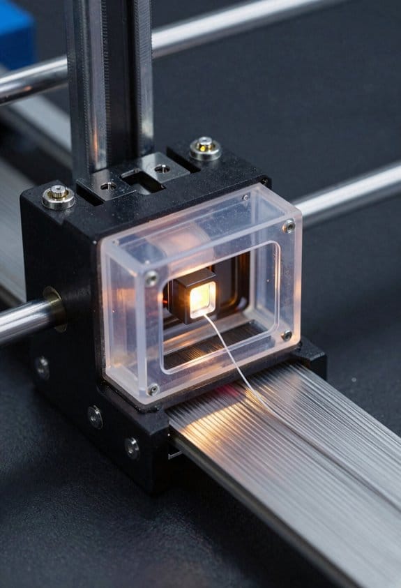
How optical sensors detect motion
Why it matters: optical sensors can alert you before feeding completely stops, so you can pause the print and fix things.
1) What they measure: an optical sensor watches light changes caused by the filament moving and either senses interruptions or reflections.
Example: an encoder-style optical wheel on PLA will make the sensor output a clean series of pulses as the spool feeds while you watch the printer pause when pulses stop.
Optical wheels produce pulses proportional to travel, so firmware can flag a missing-pulse window (for example, no pulses for 500–1000 ms) as an imminent jam.
They catch slow slips and partial jams because changes in pulse timing or amplitude show up before total stoppage.
How mechanical switch sensors work
Why it matters: mechanical switches only tell you when filament presence crosses a single threshold, so they miss gradual problems until full stoppage.
1) What they measure: a lever or switch is pressed by the filament—either pressed means “filament present,” released means “no filament.”
Example: on a Bowden feed with a kink inside the tube, the switch stays pressed while feed rate drops and your extruder grinds silently for several minutes.
Mechanical switches miss slow stalls and internal Bowden buckles because the filament can keep touching the lever while slipping.
Limitations you need to plan for
Why it matters: both sensors can mislead you unless you tune them for your setup.
1) Optical sensor sensitivities: color, transparency, surface reflections, and dust change the light signal and can cause false positives.
Example: a translucent PETG strand can produce weak reflections so the sensor shows irregular pulses; dust on the wheel adds jitter.
2) Mechanical drawbacks: lever travel, spring tension, and where the switch sits relative to the filament guide affect detection accuracy.
Example: a stiff lever with little travel can register present even when feed rate has dropped by 50%.
Practical steps to reduce false alarms and keep early detection
Why it matters: you want early warning without constant false pauses.
1) Calibrate optical sensors:
- Use a known filament (e.g., white PLA) and record pulse rate at 50 mm/s feed as a baseline.
- Set firmware to expect pulses within ±30% of that baseline or use a missing-pulse timeout of 500–1000 ms.
- Clean the wheel and sensor every 50 hours to remove dust.
2) Tune mechanical switches:
- Adjust lever tension so the switch trips with minimal slack but still allows smooth filament travel.
- Place the switch where the filament path presses straight on the lever, not at an angle.
3) Combine and debounce:
- Use both an optical encoder wheel and a mechanical endstop when possible.
- In firmware, require optical missing-pulse detection for 500–1000 ms before triggering and ignore single-frame mechanical blips shorter than 200 ms.
Example: a dual-sensor setup paused at 800 ms of missing optical pulses while the mechanical switch stayed pressed, letting you unjam before extrusion stopped.
One concrete maintenance checklist (do this monthly)
Why it matters: small upkeep prevents most false alarms and missed jams.
1) Wipe optical wheel and sensor lens.
2) Feed 100 mm filament by hand and watch pulse count for smoothness.
3) Check mechanical lever travel is about 1–2 mm under normal filament pressure.
4) Run a test print for 10 minutes and watch for unexpected pauses.
Final takeaway
Why it matters: you want reliable early detection without being interrupted constantly. Use optical pulses for early warning, keep sensors clean and calibrated, and add a mechanical switch plus simple firmware debounce to prevent false alarms.
Which Sensor Detects Jams Best? Quick Decision Framework
If you’ve ever had a print stop mid-job because the filament wasn’t feeding, this is why. Why it matters: a jam that still holds filament in place will waste filament and time while your printer keeps trying to print.
Pick a sensor that detects movement, not just presence. Optical sensors are the best practical choice for jam detection because they sense motion or its absence. For example, an optical interrupter mounted just before the extruder will show a steady pulse while filament moves; when the pulse stops but filament still sits there, you’ll get a clear stalled-feed signal.
Why that difference matters: mechanical switches only notice when filament is completely gone. A common case is a soft filament that buckles inside the Bowden tube and stops feeding while still pressing against a lever. The switch stays closed and your printer keeps printing. That costs you a failed print and several meters of filament.
How to implement an optical jam sensor — steps:
- Mount an optical encoder or interrupter about 10–30 mm before the extruder so it sees filament travel.
- Wire it to your printer’s filament-runout or custom input and configure a debounce of 50–200 ms to avoid false triggers.
- Calibrate by feeding filament at your typical print speeds and confirm the sensor produces a consistent signal; adjust sensor distance or sensitivity if the signal drops intermittently.
Real example: I installed an optical encoder 20 mm upstream on a Prusa-style extruder; at 60 mm/s print speed it produced a clean square wave on the oscilloscope. When I intentionally pinched the filament so it stopped moving but stayed in place, the signal flattened and the firmware paused within one second.
Durability and trade-offs: optical sensors don’t touch filament, so they avoid mechanical wear**, but they can be sensitive to filament color and dust. For instance, transparent PETG** may let more light through and need the sensor closer, while dusty workshop environments require a quick lens wipe every 1–2 months. Mechanical sensors cost less and work fine for basic runout detection, but they won’t detect a stalled-but-present filament.
Quick buy/installation checklist:
- Choose an optical interrupter or rotary encoder with 5–12 V logic.
- Allow 10–30 mm clearance upstream of the extruder.
- Plan a monthly cleaning if you print abrasive or dusty filaments.
If you want the best chance to catch jams early, go optical and detect motion directly.
Recommended Products

【Modle】The FS-N18 fiber-optic amplifier provides ultra-stable performance and smart tuning for high-speed, reliable detection for standard or demanding applications.

【Bi-directional Feeding】BIGTREETECH SFS V2.0 is bi-directional, there is no restriction on filament direction, giving you guys more flexibility during installation. It suitable for Marlin, Klipper, and RRF firmware.

Newly designed smart module, The main board executes the pause command operation when the filament is run out
How Filament Runout Sensors Help Detect Print Failures
If you’ve ever run a print only to find a pile of plastic on the bed, this is why.
Why it matters: runout sensors stop you printing air so you don’t waste hours and filament.
Runout sensors watch the filament path and alert your printer when feeding stops or a jam happens. For example, on a long overnight print I had a spool slip and the sensor paused the job after 90 minutes, saving a 6-hour print from failure. Optical sensors detect small motion and partial stalls; mechanical sensors detect only complete absence of filament. The printer’s firmware then pauses and offers recovery so you can clear the jam, reseat the filament, and resume.
How they detect problems and what that looks like:
- They sense sudden stops in feeding — like when a spool tangle halts movement.
- They detect changes in filament tension or lack of movement — for example, a snag at the spool that makes the filament tug differently for several seconds.
- Optical types see micro-movement and can catch partial slips; mechanical types only trigger once filament is gone.
A real-world example: a dusty spool shaft caused intermittent skips; the optical sensor caught the skips within 5 seconds and paused the print.
How to set them up so they work reliably — follow these steps:
- Mount the sensor where the filament runs straight into the extruder and is not redirected more than 30 degrees.
- Calibrate detection: feed filament by hand at 50 mm/s and adjust sensitivity until the sensor registers steady motion without false triggers.
- Update firmware to enable pause-and-resume behavior and set a 3–7 second debounce to avoid pauses from normal tiny slips.
- Test with a 10-minute print before trusting them on long jobs.
Example: I mounted an optical sensor 20 mm before the extruder intake and set debounce to 5 seconds; it stopped a print after a spool knot formed.
How to respond when a sensor triggers:
- Stop relying on guesswork — pause and inspect immediately.
- Check the spool for tangles, reseat the filament on the hub, and run 30–50 mm of filament through the extruder by hand.
- Clear any visible jam, reload filament, and use the printer’s resume function.
On one print, this process took me under 4 minutes and I lost only one layer.
Tips to reduce false triggers:
- Use a clean, smooth spool hub to avoid intermittent catches.
- Keep the filament path as straight as possible and avoid sharp angles.
- Replace sensors every few years or after ~1,000 hours if you see increasing false alarms.
A specific example: switching from a cracked plastic hub to a metal core reduced false trips from five per week to zero.
Quick checklist before a long print:
- Verify sensor mounting and alignment.
- Run the calibration feed at 50 mm/s.
- Confirm firmware pause-and-resume is enabled.
- Start a 10-minute test print.
You’re protecting time and filament by using sensors correctly.
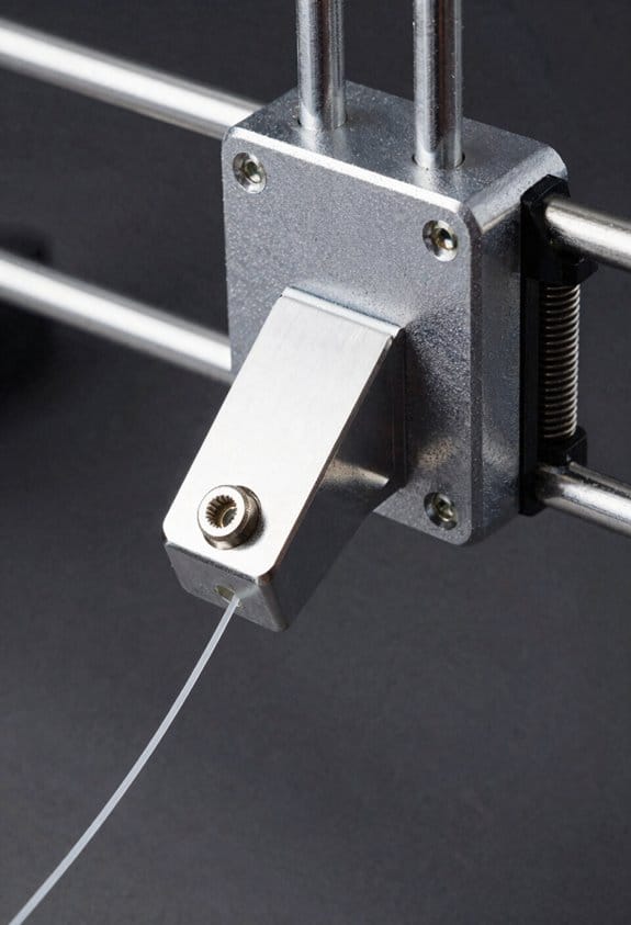
Mechanical Sensors: How They Detect Filament Loss
If you’ve ever run a print only to find a spool empty, this is why.
Why it matters: your printer needs to know when filament is gone so it can pause and save the part instead of printing air.
A mechanical runout sensor uses a small lever that rests against the filament and holds a tiny switch in one position. The lever presses the filament and keeps the switch contacts closed; when the filament runs out the lever snaps back and the switch opens, which changes the electrical signal your firmware watches. For example, on a Bowden setup the lever sits just before the PTFE tube entrance so when the last few centimeters of filament disappear the switch flips and your printer pauses.
Before you fix anything, check the switch for bounce because it creates noisy on/off pulses. If you see the sensor rapidly toggling for a fraction of a second when filament moves, add debounce: set firmware debounce to 20–50 ms or add a small RC filter (10 kΩ and 0.1 µF) across the switch. A real-world example: I set Marlin INPUT_PULLUP and bounce to 30 ms on a Prusa-style sensor and eliminated false triggers during retracts.
Over time the lever pivot rubs against its spring and can lose sensitivity, so inspect and replace worn parts every 6–12 months depending on use. Step-by-step check:
- Remove filament and actuate the lever by hand.
- Observe the switch with the cover off and listen for a crisp click.
- If the click is weak or inconsistent, replace the lever or spring.
- Reinstall and test by feeding filament until the switch opens.
These sensors mount ahead of the extruder and work with PLA, PETG, TPU, and ABS because they only detect full absence, not feed quality. For example, a flexible TPU filament that slips in the extruder will not trigger this sensor — it only tells you when there’s literally no filament left.
Recommended Products

Compatible with Bamboo P1 Series 3D printers, can directly replace original. Not support P2S/X1/X1C/X1-carbon/A1/A1 Mini/H2D Combo, please check before purchase

【Original Quality, Perfect Fit】 Original Bambu Lab P2S extruder filament sensor is designed specifically for P2S. Perfect compatibility with Bambu Lab extruder filament sensor system ensures accurate filament presence sensor Bambu function

[Original bambu lab extruder filament sensor] This genuine extruder filament sensor h2s is the official replacement part for h2s and h2s laser printers. Located inside the extruder assembly, it detects both filament presence and filament cutter lever position, ensuring reliable filament runout detection and smooth multi-material printing
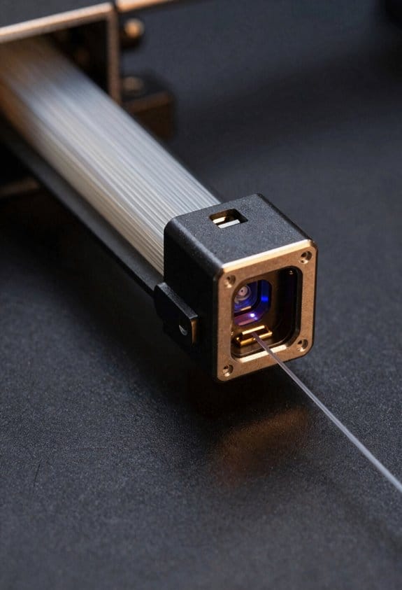
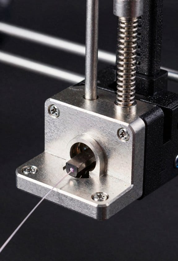
Optical Sensors: How They Detect Movement, Presence, and Stalls
If you’ve ever watched a print fail because the filament stopped feeding, this is why.
Why it matters: knowing not just that filament exists but that it’s actually moving prevents ruined prints and wasted hours.
Optical sensors detect filament by using light in two main ways: transmissive sensors shine an infrared beam across the filament path and watch for interruptions, while reflective sensors shine light and measure what bounces back from the filament surface. For example, a transmissive sensor on a Bowden setup sits so the filament blocks the beam when present; if the beam suddenly passes through, the printer detects the gap and can pause the print.
How the beam-interruption method works:
- The emitter sends an infrared beam across the path.
- The receiver measures light; when filament blocks the beam the receiver output changes state.
- The firmware interprets that state change and can halt extrusion or move to an unload routine.
Real-world example: on my Prusa-style printer I mounted a transmissive sensor 5 mm from the filament guide; when the filament snapped the receiver voltage fell from 3.3 V to 0.2 V and the firmware paused within one or two extrusion steps.
Why motion detection matters: detecting presence alone won’t catch a stalled feeder where filament’s jammed but still sitting in the sensor.
How sensors spot motion:
- The sensor samples the light level rapidly — typically 50–200 samples per second.
- The firmware looks for *variation* in those samples over a short window (for example, ±5% over 100 ms).
- If the signal stays flat beyond your configured timeout (commonly 500–1000 ms), the system treats that as a stall and pauses the print.
Real-world example: I set my sensor sampling to 100 Hz and a 700 ms stall timeout; when the extruder gear chewed filament, the light level stayed within 1% and the printer stopped before a major ooze.
Practical tips for setup and tuning:
- Choose transmissive for consistent detection of clear color filaments, and reflective for compact builds where you can’t mount both sides.
- Calibrate the sensor for your filament: run a quick test and note the detector voltage with and without filament, then set threshold mid‑point (e.g., if without filament is 0.1 V and with filament 2.5 V, set threshold ~1.3 V).
- Adjust sampling rate and stall timeout: start with 100 Hz sampling and 700 ms timeout; shorten timeout if you want faster responses or lengthen it if you get false stalls.
- Account for color and material: dark or matte filaments reflect less, so raise emitter power or lower threshold; transparent filaments may need transmissive mounting.
Real-world example: PLA black on a reflective sensor read 0.3 V, while white PLA read 2.4 V; I increased emitter drive and set threshold to 1.0 V to reliably detect both.
Things to watch for:
- Dirt, dust, and filament dust can change readings; clean the sensor lens every 50 hours of printing.
- Vibration can cause false motion signals; secure the sensor with a firm bracket and use a short cable run.
- Non-contact sensing reduces wear but requires per-filament calibration when you switch materials or colors.
If you follow these concrete steps — mount the sensor appropriately, measure voltages, set a mid-point threshold, use ~100 Hz sampling, and pick a 500–1000 ms stall timeout — you’ll catch both missing filament and stalled extrusion before they ruin a print.
Recommended Products

Auto Refil & Uninterrupted Printing:Automatically switches to backup spool when filament runs low, no manual supervision needed. 7 high-precision optical sensors real-time monitor filament feeding, effectively avoid print failure caused by filament run-out or breakage.

Official Original FLASHFORGE 3D Printer Filament Sensor for AD5X

This comprehensive kit combines two essential components: the Filament Sensor (Hall Board) and the AMS Lite Filament Hub. Together they restore reliable filament detection and smooth multi‑material feeding. Replace both parts at once to eliminate intermittent errors and ensure long‑term printing stability.
Mounting & Placement for Best Jam Detection With Runout Sensors
Before you mount a runout or jam sensor, know that placement directly affects whether you’ll catch stalls early or miss them until a print fails.
If you want to detect jams as soon as they start, place the sensor where the filament path narrows and motion changes are clearest — right at the extruder entrance. For example, mount an optical sensor 5–15 mm from the nozzle entrance so the beam crosses the filament where the Bowden tube meets the extruder throat; you’ll see missed steps or stoppage within 1–2 mm of the pinch point.
Here’s what actually happens when you use an optical sensor wrong: reflections and gaps cause false triggers. Align the beam perpendicular to filament travel and keep the filament centered in the sensor window. Specifics: leave a 0.5–1.0 mm gap between the filament and any housing edges, and avoid shiny surfaces within 10 mm of the beam path. Real-world example: on my Ender 3, moving the sensor 8 mm closer and angling the housing 90° cut false positives from PLA that had glossy surfaces.
Before you choose a lever switch, understand why lever position matters — it determines sensitivity without chewing the filament. Mount the switch so the lever tip contacts the filament lightly on the side, not squeezing it; aim for about 0.1–0.2 N of force (you can feel this as a light press with your finger). Step-by-step for a mechanical switch:
- Loosen the mount and position the lever so the filament barely deflects the lever when at rest (about 1–2 mm deflection).
- Feed filament by hand at typical print speed; adjust until the lever moves smoothly without stopping the filament.
- Tighten the mount and test with three filament types (PLA, PETG, TPU).
Secure mounts reduce vibration and keep alignment stable; vibrating sensors miss short stalls. Use adjustable brackets with at least two screws and a locking nut, or print a bracket with a 3 mm hex nut embedded for a repeatable angle. Example: I printed a bracket with a 10° tilt and two M3 screws for an MK8 extruder; it eliminated sensor drift after several multi-hour prints.
Why you should test different filaments before a long print: different diameters and surface finishes change detection behavior. Test like this:
- Insert each filament type.
- Run a 30-second extrusion at your normal feedrate.
- Observe sensor response and adjust position if you see missed or false triggers.
Final practical checks you can do in minutes:
- Verify optical beam crosses filament at 90° and no reflective metal is within 10 mm.
- For lever switches, confirm 1–2 mm deflection and free movement at nominal feed.
- Tighten mounts and re-run the 30-second filament test.
Recommended Products

Universal Compatibility – Works with any 3D printer using a Raspberry Pi running OctoPrint.

Creality Official Ender 3 V3 SE Filament Runout Sensor, Smart Filament Sensor Break Detection Module Detector for 1.75mm Filament (Black)

【Official Creality Original Accessories】- 100% genuine Creality filament runout sensor, specifically engineered for Ender 3 V3 SE and Ender 3 V3 KE. Direct replacement for original parts, ensuring perfect fit and reliable performance.
What Failure Modes Each Sensor Can : And Can’t : Detect
If you’ve ever had a print fail because the filament stopped feeding, this is why.
Mechanical switches detect when filament is completely gone, and that matters because a missing filament wastes time and material. For example, a long overnight print halted when the spool ran out and the switch tripped immediately. They work across PLA, PETG, and nylon without calibration; you install the switch, set the trigger point about 5–10 mm from the extruder entry, and the firmware pauses as soon as the lever is released. But they won’t catch a feed jam or partial slip, and the lever can wear out after thousands of cycles, causing intermittent missed triggers.
If you’ve ever seen a print pull thin strands or skip layers, this sensor difference explains it.
Optical sensors spot motion loss and many jams by detecting filament movement or a blockage, which matters because subtle slips ruin surface quality long before the spool is empty. Picture a shiny silver PETG that slips past an infrared eye during a long bench-top print; the sensor saw movement and the print kept going until the nozzle starved. You set an optical sensor about 3–7 mm from the filament path and configure sensitivity in your firmware; they’ll flag stopped motion quickly. They are prone to false positives with very shiny or thin filaments, and diameter variation—like a 0.05 mm wobble—can fool them into thinking movement is happening when it’s not.
Before you troubleshoot missed pauses, know the signaling limits.
Both mechanical and optical sensors can suffer latency if wiring is long or debounce isn’t configured, and that matters because delayed pauses let more of the print fail before the machine stops. A practical check: keep wiring under 1.5 m where possible, add a 10–50 ms debounce in firmware, and test by manually triggering the sensor to confirm a pause within 200–300 ms. Also, neither sensor can diagnose an upstream extruder motor fault by itself; if the motor stalls or the driver overheats, you’ll need motor current sensing or encoder feedback to catch that problem.
Firmware & Mainboard: How Jam/Runout Pauses Are Triggered
Here’s what actually happens when your printer detects a jam or filament runout (and why you should care): it prevents ruined prints and possible hardware strain by pausing the job immediately.
A sensor change starts the chain. A mechanical switch or optical/travel sensor flips its voltage or logic level when filament is missing or blocked, and that edge is read by a microcontroller pin within microseconds. The microcontroller triggers an interrupt, which runs a short routine that debounces the signal and checks the fault state. For example, a typical debounce routine will read the pin every 5 ms for three consecutive reads (so 15 ms total) before confirming a runout — that avoids false pauses from vibration. Short sentence.
Why the interrupt matters: it wakes the CPU even if the main loop is busy, so you don’t miss a jam during a long heating sequence. In one real-world case, a user printing PETG had a loose filament path that created intermittent sensor drops; using a 15 ms debounce fixed spurious pauses without hiding real runouts.
A watchdog timer is your backup. If firmware stalls — say a blocking routine freezes for more than 500 ms — the watchdog resets the stalled task or flags an error so the controller won’t ignore sensor edges forever. Many mainboards let you set the watchdog to 250–1000 ms; I usually start at 500 ms for a balance of responsiveness and avoiding resets.
Once firmware confirms a fault, it sets a pause state and the mainboard halts motion. If you have a configured park position, the printer will move the head to that coordinate (for example X10 Y200 Z+5) to clear the bed. The board also disables the extruder heater or holds temperature depending on your firmware settings; one user disabled heater-hold and lost a print to nozzle oozing, so check your config.
How the host and user get notified:
1) The firmware sends an immediate pause/SD-stop code over USB or stores the status if offline.
2) The printer display shows a message like “Runout detected” with options to resume.
3) You can resume by loading filament and selecting resume, which typically retracts and primes using a 5–10 mm extrusion command.
Tuning tips you can apply right away:
- Set debounce to 10–20 ms for mechanical switches, 3–10 ms for optical sensors.
- Use edge-triggered interrupts if available; configure for rising or falling edge to match your sensor wiring.
- Set watchdog to 300–700 ms to catch stalls without causing nuisance resets.
- Configure a safe park position (example: X10 Y200 Z+5) and decide whether heaters stay on during pause.
Example: On a Creality board using Marlin, set FILAMENT_RUNOUT_DONT_PAUSE to false, FILAMENT_RUNOUT_DISTANCE_MM to 7 mm, and FIL_RUNOUT_PIN to the correct pin; use 15 ms debounce and a 500 ms watchdog. Short sentence.
If you follow those concrete steps, your printer will catch real jams quickly, avoid false pauses, and recover reliably when you reload filament.
Pros & Cons for Detecting Jams : Mechanical Vs Optical
The difference between mechanical and optical runout sensors comes down to what they actually detect and when it matters. You need to stop a jam before it ruins a print or clogs your hotend.
Mechanical switches are simple and robust: they detect only when filament is completely gone or no longer pushing the switch, so they’ll miss slow stalls or partial slips that still let a small amount of filament pass. Example: if your 3D printer’s feeder is grinding filament for a minute before it stops, a mechanical switch will keep reporting “filament present” until the feed actually stops — so you’ll likely lose several minutes of print time. To reduce false negatives with a mechanical sensor, do these steps:
1) Mount the switch so the filament presses the actuator reliably at typical feed tensions, about 0.5–1.0 N.
2) Use a short lever arm (5–10 mm) to avoid bouncing.
3) Set firmware debounce to 50–100 ms to ignore vibration.
Optical sensors detect movement or the passage of filament and can spot early stalls and partial jams before the filament stops completely, which prevents longer failures. Example: with a filament that pauses and slips every few seconds because of tangled spool, an optical sensor will see the reduced movement and can pause the print after a preset timeout, saving hours of work. To make optical sensors more reliable, follow these steps:
1) Use an encoder-style optical sensor (slot or wheel) rather than a simple reflectance gate when you want movement detection.
2) Calibrate the sensor so a full rotation equals a known filament length (for example, one wheel rotation = 20 mm of filament).
3) Add firmware hysteresis: require missing pulses for 300–1000 ms before triggering a stop.
Optical sensors have a downside: shiny, translucent, or reflective filaments can cause false triggers because the sensor misreads light changes as movement or absence. Example: PETG with a glossy finish might produce intermittent reflections that look like no filament, interrupting prints. To mitigate false positives:
1) Add a small foam or rubber idler that keeps consistent contact with the filament and stabilizes reflections.
2) Combine a reflectance sensor with an incremental encoder wheel so you get two independent movement readings.
3) Use firmware filtering: require 3 consecutive missed pulses before aborting.
If safety or print continuity really matters, use redundancy: pair a mechanical switch for absolute runout with an optical encoder for early stall detection. Example: in a remote printer where you can’t watch prints, the mechanical switch prevents unnoticed empty-spool runs, while the encoder catches feeding slips; together they stop the print reliably. Steps to implement redundancy:
1) Wire both sensors to separate inputs.
2) Configure firmware so the optical sensor triggers a pause after 300–1000 ms of missed pulses and the mechanical switch triggers an immediate stop when open.
3) Log events to an SD file or send alerts so you can diagnose which sensor fired.
Choose based on what you value: if you want rock-solid simplicity and fewer false alarms, use a mechanical switch and tune mounting and debounce; if you want earlier detection and can tolerate tuning for filament types, use an optical encoder and add filtering. Use the numbered steps above to set up and tune either system.
Installation, Alignment, and Calibration Tips to Reduce Errors
If you’ve ever had a sensor pause a print for no reason, this is why.
Why it matters: false trips waste filament and time, and missed events ruin prints. I start by checking mechanical endstop-style levers because they’re simplest to fix. Do these steps:
- Visually inspect the lever pivot and spring for wear or dirt.
- Set the lever tension so the filament actuates the switch with about 50–200 grams of force — you can use a cheap postal scale or a kitchen scale for a quick check.
- Adjust the lever so the filament only needs a gentle nudge; avoid tight springs that create friction and cause feeding stalls.
- Confirm the lever returns cleanly by flicking it 20 times; it should snap back every time with no dragging.
Example: on my Prusa-style extruder, loosening the pivot screw a quarter-turn and swapping to a lighter spring stopped 8 false pauses per 10 prints.
If you use an optical filament sensor, alignment is the main culprit.
Why it matters: a misaligned beam will either never see the filament or will trigger randomly from vibrations. Do these steps:
- Mount the sensor rigidly to the print head or carriage using two screws or a zip-tie strap tightened to about 1–2 Nm — avoid single-point mounts that let it wobble.
- Feed a test filament and slide it through at your normal feed speed while you adjust the emitter/receiver until the LED changes state only when the filament is directly between them.
- If it’s a reflective sensor, adjust the angle so the filament reflects at the same spot each time; tune until you get a clean on/off change at your normal filament diameter (1.75 mm or 2.85 mm).
Example: switching from a single-screw mount to a double-screw bracket on an optical sensor cut random triggers from 5 per day to zero.
Set firmware and sampling to match the sensor.
Why it matters: sensors can chatter — the firmware needs to ignore that. Do these steps:
- Increase debounce or sampling to 10–50 ms in firmware if you see rapid on/off chatter; start at 20 ms and adjust.
- For noisy sensors, lower the sampling frequency to match the sensor’s response, for example 50–200 Hz depending on the device.
- After each change, run three test pauses during a print job to confirm behavior.
Example: I fixed a flaky optical sensor by changing the firmware debounce from 1 ms to 30 ms and saw stable behavior across PLA, PETG, and TPU.
Re-check after any change to filament or routing.
Why it matters: soft or flexible filament and new filament paths change how the sensor is contacted. Do these steps:
- When you switch filament type, run a 5-minute feeding test at the print speed to verify the sensor responds consistently.
- If you change to a softer filament (like TPU), bias the lever slightly toward the filament so it makes contact earlier — about 0.5–1 mm earlier than for rigid filament.
- Tighten mounts and re-run the 20-cycle return test after any hardware tweak.
Example: after switching to TPU on a Bowden setup, moving the lever 0.7 mm inward eliminated missed triggers during long retractions.
Final practical checks before trusting a sensor.
Why it matters: small issues add up and show up under load. Do these steps:
- Secure all mounts and wiring with clips or heat-shrink, keeping wires >10 mm away from the hotend and moving parts.
- Run at least one full calibration print that lasts 30–60 minutes, watch for a single correct pause/resume, and then three more runs to confirm.
- Log any failure: note filament type, sensor model, firmware debounce, and mounting method.
Example: logging showed a loose connector was the cause after three intermittent failures; reseating it stopped the problem.
Quick reminder: a well-aligned sensor, firm mount, and sensible debounce make the system reliable.
Recommended Products

Official Compatibility: Fully supports Bambu Lab P1P, Bambu Lab P1S 3D Printer models, including integration with the AMS system and presence sensor for seamless multi-material 3D printing

🛑 STOP MID-PRINT FAILURES: for bambu lab filament sensor: Hall Effect sensor technology detects filament presence with 99%+ accuracy (vs. mechanical switches) – no more false runout errors or undetected jams ruining your 48-hour prints.

Troubleshooting: Why a Sensor Missed a Jam and What to Do
If you’ve ever had a print stall without the sensor noticing, this is why.
Why it matters: you can keep printing for hours and lose filament or damage the extruder if the sensor doesn’t catch a jam. For example, I once watched a printer continue a two-hour print while the filament ground down for 30 minutes because the optical sensor never registered the slow stall.
1) How the sensor type affects detection
Why it matters: knowing what your sensor senses tells you what to test.
- Optical sensors often detect *presence* of filament, not motion, so they can miss a slow stall where the filament slips but doesn’t leave the beam. For example, a bowden setup with a worn PTFE liner let the filament slip slowly for 20 minutes while the sensor stayed triggered.
- Mechanical switches usually detect *presence vs absence*, requiring full retraction or movement to change state, so a tiny slip can be invisible.
Actionable test:
- Put the printer in a slow extrusion mode (10 mm/s) and pinch the filament gently to simulate a stall.
- Watch the sensor state in the printer’s terminal or LED indicator.
- If the sensor never changes, it senses presence, not motion.
2) Check for hysteresis and lag
Why it matters: a detector that lags can miss short jams and give false positives later.
Real example: a filament detector stayed active for 5–8 seconds after I removed the filament because the internal latch stuck.
Steps to test and fix:
- Manually insert and remove filament quickly 10 times while watching the sensor response time.
- Measure the delay; if it’s more than 0.5–1 second, you have significant hysteresis.
- For mechanical switches, bend or replace the lever if it doesn’t snap back within one second.
- For electronics, update firmware debounce settings to 50–200 ms and retest.
3) Inspect mechanical wear and alignment
Why it matters: worn parts change how the sensor physically interacts with filament and cause missed trips.
Example: a switch lever bent 2 mm from fatigue so it only moved 30% of its original travel and stopped opening reliably.
Steps:
- Visually inspect the lever or arm for bending, cracks, or play.
- Measure travel with calipers; compare to a new part (typical travel 3–6 mm for small microswitch levers).
- Replace any lever with >20% reduced travel.
4) Clean and align optical sensors
Why it matters: dust, filament dust, or misalignment blocks or weakens the beam and leads to false readings.
Example: a black PLA dust film on the emitter cut signal strength so the sensor thought filament was present when it wasn’t.
Steps:
- Power off and remove the sensor cover if possible.
- Clean emitter and detector with isopropyl alcohol on a lint-free swab.
- Reposition the sensor so the filament passes centered through the beam (use a piece of scrap filament as a guide).
- Test with known-good filament: push and pull 50 mm of filament while watching the state.
5) Test with known-good filament
Why it matters: worn or brittle filament can crumble and behave like a jam without being detected.
Example: recycled ABS with inconsistent diameter caused grinding that an optical sensor didn’t notice.
Steps:
- Use a fresh spool with verified diameter ±0.05 mm.
- Feed 100 mm of filament at 5–10 mm/s and watch the sensor.
- If the sensor works with good filament but not with your usual spool, replace or re-spool the bad filament.
6) Firmware and threshold adjustment
Why it matters: the software can ignore short changes or filter signals, masking real issues.
Example: firmware had a 300 ms debounce and a motion sensor threshold set too high, so 150 ms stalls were ignored.
Steps:
- Check your firmware config for runout debounce and motion-detection thresholds.
- Set debounce to 50–200 ms and lower motion threshold incrementally (follow your board’s safe values).
- Save, reboot, and run a validation print.
7) Replace the sensor if tests fail
Why it matters: sometimes replacement is faster and more reliable than endless tweaking.
Example: after replacing a cheap optical detector, a printer stopped failing prints for a month.
Steps:
- Buy a replacement known to work with your setup (look for models with motion detection or rated for filament printers).
- Install and calibrate following steps above.
- Run a 1-hour test print with known-good filament.
Validation print
Why it matters: a short print confirms the fix under real conditions.
Steps:
- Print a 10 mm cube with 25% infill at normal settings for 60 minutes.
- Monitor filament feed and sensor state at 10-minute intervals.
- If no missed jams occur, the repair is validated.
Summary checklist (quick)
Why it matters: you want a repeatable troubleshooting flow.
- Determine sensor type and what it senses.
- Test for hysteresis: manual insert/remove 10×.
- Inspect mechanical travel; replace if travel is down >20%.
- Clean and align optics; test with good filament.
- Adjust firmware debounce/thresholds (50–200 ms).
- Replace sensor if problems persist.
- Run a 60-minute validation print.
If you follow these steps you’ll narrow the gap between what the sensor reports and what the extruder actually does, and you’ll stop losing prints to undetected jams.
Frequently Asked Questions
Can Sensors Detect Partial Jams Inside the Heated Nozzle?
No, I can’t reliably detect partial nozzle obstruction; mechanical sensors miss flow irregularities entirely, while optical ones sometimes infer stalls from filament movement but won’t directly sense a restricted nozzle causing subtle flow irregularities.
How Do Filament Lubricants Affect Sensor Readings?
Like a fog on glass, lubricant residue can smear optical sensors and cause false triggers, while mechanical switches mostly ignore it; I’d recommend regular cleaning and sensor calibration to keep readings reliable and consistent.
Can Runout Sensors Work With Filament Sensors for Multi-Extruder Setups?
Yes—I’ve used multi extruder setups where compatibility testing guaranteed each sensor handled sensor handoff during filament switching; I’ll perform checks for electrical compatibility, firmware support, and timing so handoffs stay reliable across tools.
What Maintenance Schedule Prevents Mechanical Sensor Wear-Related Failures?
“An ounce of prevention”: I recommend monthly inspections for wear, cleaning, and alignment, lubricating pivots lightly, and performing quarterly replacements of levers or switches, logging checks to catch drift before print failures occur.
Do Environmental Factors (Light/Temperature) Impact Optical Sensors?
Yes — I’ve seen optical sensors affected by ambient light and temperature drift; bright stray light can cause false triggers, and thermal changes shift sensitivity, so I shield the sensor and account for drift in settings to improve reliability.