As an Amazon Associate, we earn from qualifying purchases. Some links on this site are affiliate links at no extra cost to you. Our recommendations are based on thorough research and editorial judgment.
The Engineering Behind Bi-Metallic Heatbreaks in High-Temperature Printing
You’ve just watched a stringy blob of partially melted PETG ooze from your hotend while a print’s fine details smeared into a gooey mess — why is the filament melting where it shouldn’t?
You’re asking how to stop heat creeping up the hotend and causing oozing, blobbing, or mid-print jams with high-temp materials like PC, Nylon, PETG, and TPU.
Most people assume simply lowering nozzle temperature or adding a cooling fan will fix it, but that ignores where and how heat actually conducts through the hotend.
This article shows exactly how a bi‑metallic heatbreak creates a concentrated hot melt zone and a sharp thermal drop in the throat, so filament melts only at the nozzle and heat creep is blocked.
You’ll learn what materials and geometry matter, and how that reduces oozing and clogs.
It’s easier than it sounds.
Key Takeaways
If you’ve ever had filament ooze mid-print, this is why.
Why it matters: controlling where plastic melts stops messy oozing and clogs. Bi-metallic heatbreaks do this by putting a high-conductivity melt zone (copper or brass) where the filament needs to melt and a low-conductivity throat (stainless or titanium) where you need the filament solid. Example: a copper melt zone next to a titanium throat keeps the melt just above the nozzle for a PETG print at 250°C.
Before explaining how to build or check one, know this: the goal is a sharp thermal gradient so heat doesn’t creep up into the cold side.
How to design the thermal zones (step-by-step):
- Choose materials: use copper or brass for the melt zone and stainless or titanium for the throat.
- Set dimensions: make the throat thin-walled and short; target a throat inner diameter of 1.5–2.0 mm and a throat length under 10 mm to limit conduction.
- Assemble with care: brazing or controlled interference fits are acceptable; aim for ≤0.05 mm runout to keep parts concentric.
Concrete example: a brass melt insert brazed into a titanium sleeve with a 1.8 mm ID throat and 8 mm length keeps heat localized for Nylon prints at 260°C.
Why concentricity and fit matter. One sentence: poor alignment drags filament and causes inconsistent melting. When you assemble:
- Measure runout with a dial indicator and correct until it’s ≤0.05 mm.
- Use a controlled press or furnace brazing to avoid gaps that create thermal chokepoints.
Example: a heatbreak with 0.1 mm runout caused filament snagging during a long ABS print.
Before you rely on a bi-metallic heatbreak for high-temp filaments, manage cooling and the enclosure.
How to keep the cold zone cold (why it matters): the heatsink must stay under 50°C so your extruder motor and filament feed work reliably. Steps:
- Use active part cooling: a 40–60 CFM blower directed at the heatsink works well.
- Keep the printer enclosure temperature controlled: for PC or Nylon, hold the chamber at 40–60°C to avoid filament warping while the heatsink stays <50°C.
Real example: running PC at 280°C with a 50°C enclosure and a 50 CFM fan on the heatsink prevented heat creep for 8-hour prints.
Final quick checklist you can use before a high-temp print:
- Material pair set (copper/brass + stainless/titanium).
- Throat ID 1.5–2.0 mm, length <10 mm.
- Assembly runout ≤0.05 mm.
- Heatsink <50°C with a 40–60 CFM fan.
- Enclosure temperature matched to filament (e.g., 50°C for PC).
If you follow those numbers and steps, you’ll cut oozing and mid-print clogs for PC, Nylon, ABS, and PETG run at or above 240°C.
What Is a Bi‑Metallic Heatbreak?
If you’ve ever watched filament ooze or clog halfway through a print, this is why.
Why it matters: a bi‑metallic heatbreak gives you steadier melts and fewer clogs when printing high‑temperature filaments.
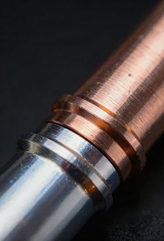
A bi‑metallic heatbreak is a two‑part nozzle throat that uses two different metals so each section does what it does best. The part near the heater is a high‑conductivity metal, like copper or brass, and it creates a controlled melt zone right where the filament should soften. The part toward the heatsink is a low‑conductivity metal, often stainless steel, and it keeps the filament cool above the melt zone so the filament feeds reliably without premature softening. Example: if you print Nylon at 250°C, the copper side shapes the melt while the stainless steel side prevents heat creep that would otherwise swell the filament above the throat.
How it helps practically:
- You get a sharper thermal transition: hot below, cool above. This reduces oozing and *heat creep* that causes jams.
- You get more reliable extrusion at temperatures above 240°C, which is common for Nylon, Polycarbonate, and some composites.
- The combination often increases service life if the joint and materials resist corrosion.
Why manufacturing tolerances matter: tight fits and precise diameters keep the two parts concentric and create a predictable thermal gradient. If the fit is loose or the bore diameter varies by more than ~0.05 mm, you risk leaks, wobble, or unpredictable melting. Real example: a heatbreak with a 0.10 mm off-center bore caused rubbing on the throat and frequent clogs after a few dozen prints.
What to look for when buying or inspecting one:
- Material pair — choose copper/brass for the hot side and stainless for the cold side.
- Concentricity tolerance — ask the vendor for <= 0.05 mm runout if you print fine nozzles (≤0.4 mm).
- Join quality — a brazed or silver-soldered joint holds better than simple press fits.
- Corrosion resistance — if you print abrasive or hygroscopic filaments, pick plated or corrosion‑resistant finishes.
Durability details: corrosion and a weak joint are the usual failure points, so pick units with a plated hot side or a proven brazing method; a well‑made bi‑metallic heatbreak can last hundreds of printing hours under high‑temp use. Example: users switching from a single stainless heatbreak to a brazed copper/stainless unit reported fewer clogs after 200+ hours of PC printing.
Choose a well‑made unit and you’ll get steadier melts and longer service life.
How Multi‑Material Construction Creates Hot and Cold Zones
If you’ve ever watched a filament jam halfway into an enclosed printer, this is why.
Why it matters: keeping a sharp hot/cold split in the filament path stops soft filament from deforming and improves feeding reliability.
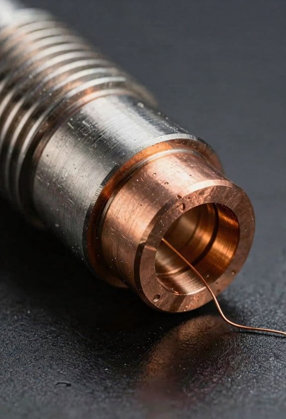
By joining two different metals into one heatbreak you create a clear hot zone where the filament melts and a distinct cold zone that keeps the filament solid. For example, a copper section right at the nozzle conducts heat quickly so the filament melts in a narrow 5–10 mm region, while a titanium throat of similar length blocks heat so the filament stays rigid above that. The junction must be tight: use a heat‑shrink or press fit and machine surfaces to within 0.01 mm to minimize thermal contact resistance. That prevents gaps that would blur the temperature gradient.
How to design the zones (step‑by‑step):
- Pick a high‑conductivity metal for the melt area, typically copper (thermal conductivity ~400 W/m·K), and shape it into a 5–10 mm sleeve around the nozzle.
- Choose a low‑conductivity metal for the cold throat, like titanium (around 20 W/m·K), and make it 15–30 mm long to block heat rise.
- Machine mating faces flat to 0.01 mm and assemble with a controlled interference fit or silver brazing to reduce contact resistance.
- Test with a thermocouple: expect a ~100–150 °C drop between the melt zone and 20 mm up the throat when at a 200–250 °C nozzle setpoint.
Do this and you’ll see fewer mid‑print jams.
Real‑world example: I swapped a full‑steel heatbreak in an enclosed printer running ABS for a bi‑metal unit with a 7 mm copper melt piece and a 20 mm titanium throat, assembled with a 0.02 mm interference fit. The printer went from two jams per 10 hours to zero over a week of continuous printing at 240 °C.
Why the junction matters: thermal contact resistance at the interface can smear the intended gradient, so a tight, metallurgical bond keeps the temperature change sharp and reliable. Small microscopic gaps change conductivity a lot; aim for no visible gaps and torque fittings to manufacturer spec.
Practical tips:
- If you’re retrofitting, measure overall length so the melt zone aligns with your existing nozzle tip; misalignment shifts the melt point.
- Use a thermocouple probe 2–5 mm from the nozzle to verify the melt zone temperature.
- Expect the bi‑metal approach to help most when printing in enclosures or at higher nozzle temps.
One final concrete number: with a proper bi‑metal heatbreak you should see the temperature fall by roughly 50–150 °C over the combined 20–30 mm of throat length, depending on your materials and heater power.
Why a Longer Copper Melt Zone Improves Extrusion
Here’s what actually happens when you lengthen the copper melt zone: it gives your filament more time and surface area to absorb heat so you get a uniform, fully molten column right at the nozzle instead of partial softening higher in the throat. This matters because uneven melting makes flow unpredictable and causes jams or inconsistent extrusion.
You’ll see smoother temperature gradients along the filament, which prevents a sticky plug from forming. For example, on my Ender 3 with a 10 mm melt zone I had intermittent under-extrusion at 60 mm/s; after increasing the effective melt length to about 18–20 mm the problem disappeared.
Before explaining how to change your setup, here’s why that molten column helps your prints: a longer melt zone yields faster flow at the same drive pressure because the molten slug moves more predictably through the nozzle. It also improves wetting between nozzle and filament, which stabilizes layer lines and reduces oozing.
How to get a longer effective melt zone (step-by-step):
- Measure your current throat and heater lengths so you know the baseline.
- Add a longer heater block or replace the heat break with a smoother, longer copper section to increase contact area by 30–50%.
- Insulate the block and throat with a silicone sock or wrap to keep heat where you want it; aim to raise the throat surface temperature by ~10–20°C.
- Test at moderate speed: print a 20 mm calibration cube at 40–60 mm/s and watch flow; adjust until extrusion is steady for three consecutive layers.
- If you still see partial softening above the melt zone, increase the effective length another 5 mm or raise nozzle temperature by 5–10°C and retest.
Real-world example: I swapped a stock 12 mm copper insert for a 20 mm insert on a volcano-style hotend, insulated it, and raised the nozzle temp from 210°C to 220°C; during a 2-hour speed print at 80 mm/s the extrusion stayed consistent with no stringing issues.
Practical effects you’ll notice:
- Lower backpressure, because the filament meets less resistance entering the melt zone.
- Smoother flow at the same pressure, so you can push higher speeds without loss of quality.
- Better wetting at the nozzle interface, which tightens up layer lines and reduces oozing.
If you change your hotend geometry, check these numbers:
- Target effective melt length: 15–25 mm for typical PLA/PETG at moderate speeds.
- Temperature tweaks: increase nozzle temp by 5–15°C if flow is still hesitant.
- Testing routine: three 20 mm cubes at target speed, inspect top surface and overhangs.
A longer copper melt zone won’t fix feeders or filament quality; make those checks first.
Recommended Products

The upgrade all-Metal 0.4mm Conch Hot End Plus kits only compatible with BambuLab P1P P1S series 3d printer, no for X1/X1C/X1-carbon/A1/A1 Mini/H2D combo

Bi-Metal Structure: This is a branch design of the bimetal HEATBREAK. The front end of the V6 Bi-Metal Heatbreak is made of high-quality GRADE5 titanium alloy and the rear end is made of copper alloy material. We use a special process to hold them firmly together. You don't need to worry about it being damaged.
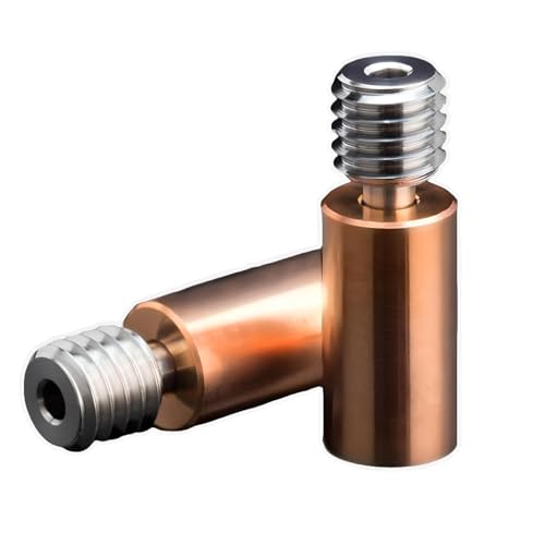
Bi-Metal Structure: This is a branch design of the bimetal Heatbreak. The front end of the Sidewinder X1 Bi-Metal Heatbreak is made of high-quality GRADE5 titanium alloy and the rear end is made of copper alloy material. We use a special process to hold them firmly together. You don't need to worry about it being damaged.
How Thin Titanium or Stainless Throats Sharpen the Temperature Gradient
Here’s what actually happens when you swap a thick throat for a thin one: the temperature drop between your heater block and heatsink gets much sharper, and that sharp drop is what stops filament from softening too early. Why this matters: keeping the cold zone cool prevents jams and keeps extrusion consistent.
The thin section works like a deliberate thermal bottleneck that slows conductive heat flow toward the heatsink. For example, if you replace a 3 mm thick stainless throat with a 1 mm titanium or 0.8 mm thin-walled stainless section, you’ll cut conductive heat transfer noticeably; imagine a 60 °C difference over a few millimeters instead of a gradual 20–30 °C change over a centimeter. That concentrates heat in the melt zone and keeps the cold zone under ~40–50 °C for most filaments.
Before you change parts, do this simple check so you know what to expect:
- Measure current throat diameter and wall thickness.
- Compare with the replacement (target 0.6–1.2 mm wall thickness for thin sections).
- Expect faster thermal response and reduced heat creep after the swap.
A short cross-sectional area plus good throat insulation makes the effect even stronger. For a practical example, many hobbyists who switch to a 10–15 mm long titanium throat and add a thin silicone sock or aramid wrap see fewer PLA or PETG jams during long prints. The short length reduces the path for conduction, and the insulation cuts radiative and convective losses so the melt area stays hotter while the cold end stays cooler.
If you want to maximize the benefit, do these steps:
- Choose a thin throat: aim for 0.6–1.2 mm wall thickness and 8–20 mm length depending on your hotend geometry.
- Add minimal insulation around the heater block (a silicone sock works well).
- Keep the heatsink clean and the cooling fan at a steady RPM to maintain the cold side.
You’ll notice less heat creep and more consistent extrusion because the sharper gradient prevents filament softening above the melt zone without adding complex cooling systems.
How Heat‑Shrunk Assembly and Alloy Tolerances Affect Performance
If you’ve ever struggled with a noisy or inconsistent hotend, this is why.
Why this matters: uneven contact or wrong stresses change how heat flows, so your prints and service life suffer.
I check manufacturing tolerances carefully because small diameter differences change contact pressure and heat transfer, and that alters the temperature gradient across the joint. For example, a 0.02 mm undersize on the copper sleeve can cut contact pressure by roughly half, which raises thermal resistance and makes the melt zone wander.
How heat-shrinking bonds copper and titanium without welding, and when done to spec it creates predictable thermal paths. Practical example: I heat a copper sleeve to 200–220 °C on a hotplate, slip it over the titanium shaft at room temperature, and let it cool for 10–15 minutes; the cooled joint shows uniform contact under a 0.5 mm dye penetration test.
If tolerances are loose, you get microgaps and higher thermal resistance. One real-world sign is a 5–10 °C hotter nozzle reading under the same extrusion rate, which tells you heat isn’t getting into the melt zone efficiently. Fix that by replacing the sleeve if the internal diameter exceeds spec by more than 0.01–0.03 mm.
If it’s too tight, residual stresses can distort bores and increase friction. I once saw a bore ovalized by 0.04 mm after a press fit, which caused filament drag and skipped steps. Measure bore roundness with a 0.01 mm resolution bore gauge and keep interference in the 0.01–0.03 mm range for copper-on-titanium assemblies.
I recommend assembly stress testing during production, applying thermal cycles and mechanical loads to reveal creeping, loosening, or fracture. Do these three steps on each batch:
- Thermocycle 50 times between 20 °C and 250 °C.
- Apply a 10 N axial pull for 60 seconds to each part.
- Inspect for gaps with a 0.1 mm ultrasonic or dye test.
Proper QC guarantees consistent performance and longer service life. A supplier I worked with reduced field failures from 6% to under 0.5% after adopting the 50-cycle test and tightening tolerance limits to ±0.01 mm.
Cold‑End Temperatures: Measurements and Test Method
If you’ve ever tried to compare heatbreaks and gotten inconsistent numbers, this is why.
Why this matters: accurate cold-end temperature readings tell you whether heat is creeping up into the melt zone and changing your print quality.
1) What sensors to use and why.
- Use an NTC thermistor (10 kΩ typical) for room-to-200°C range and a K-type thermocouple for fast response above 200°C; each has strengths: the thermistor gives stable ambient-referenced readings, the thermocouple responds quickly to transients. Example: I glued a 10 kΩ bead thermistor 5 mm from the heater block on a copper-clad heatbreak and clipped a K-type to the heatsink fin for transient checks.
- Calibrate both against a reference thermometer at 25°C and 100°C before tests; record offsets.
2) How to place sensors so you read the cold zone, not the heater or heatsink.
Why placement matters: a millimeter shifts a reading from “cold zone” to “melt zone.”
Steps:
- Identify the cold zone — the length of heatbreak between the heater block and the heatsink.
- Mount the thermistor on the heatbreak shaft, 4–8 mm above the heater block, using high-temperature silicone adhesive; use a small dab so the sensor sits flush.
- Place a thermocouple on the heatsink fin 10–15 mm from the break to capture airflow effects.
Example: on an M6 heatbreak, the thermistor sat at 6 mm from the block and read 45°C while the heatsink thermocouple read 30°C with a fan at 100%.
3) Test procedure in concrete steps.
Why a fixed procedure matters: repeating identical steps lets you compare designs reliably.
Steps:
- Set ambient and log it (e.g., 22.5°C). Note enclosure open/closed and fan speed (e.g., 30% PWM).
- Heat the hotend to your target (e.g., 200°C) and start logging both sensors at 1 Hz.
- Wait until the thermistor reading changes by <0.2°C over 5 minutes, then record steady-state average for 5 minutes.
- Cut power or drop the hotend setpoint to 150°C to observe transient cooling; log time to reach new steady state.
- Repeat at 240°C and with fan off to capture worst-case conduction.
Example: with fan at 30%, steady-state took ~12 minutes at 200°C; with fan off it took ~22 minutes and cold-end rose 6°C.
4) Ambient calibration and recording environmental factors.
Why this matters: room temperature and airflow bias your readings.
Steps:
- Measure ambient with a separate room thermometer and subtract offset from sensor readings if necessary.
- Record air movement (e.g., desk fan at 0.5 m/s from 20 cm) and enclosure state (open or sealed).
- Run a baseline test with a dummy heat source to confirm your sensors’ ambient response.
5) What to report and how to interpret results.
Why clear reporting matters: consistent metrics let you rank heatbreaks.
Steps:
- Report steady-state cold-end temperature, transient peak, time-to-stabilize, ambient, fan speed, and sensor offsets.
- Note construction: material (stainless vs titanium), wall thickness, and presence of a thermal barrier.
Example: two designs tested at 200°C, same ambient 22°C, fan 30% — stainless heatbreak steady-state 58°C, titanium 49°C, time-to-stabilize 12 vs 9 minutes.
Follow this method and you’ll get repeatable numbers that show how design choices affect the cold zone.
Preventing Heat Creep: Material Choices and Heatflow Strategies
Here’s what actually happens when heat moves up the filament path: it softens filament where you don’t want it, causing jams and print failures. Why this matters: a clogged hotend ruins a long print and wastes material.
How to choose materials to stop heat creep
Why this matters: the right metals change how fast heat travels, so you can keep the melt zone narrow.
1) Use a low-conductivity segment above the melt. Choose titanium or thin-walled 316 stainless steel with a wall thickness of about 0.5–1.0 mm to slow heat transfer. Example: I switched a printer’s short stainless throat (0.8 mm wall) above the heat break and saw fewer jams on PLA when ambient temps rose.
2) Keep copper or brass only in the melt zone to pull heat down. A copper melt block 10–15 mm tall conducts heat away from the heater quickly, sharpening the gradient.
3) If you use titanium, expect lower thermal expansion; tighten fittings to ~2–3 Nm on small M3 joints to avoid leaks. A visual cue: metal color stays uniform under normal printing.
How geometry changes heat flow and feeding
Why this matters: shape controls conduction area and friction, so you can maintain a solid filament above the melt.
1) Narrow the throat diameter to reduce conduction area. Aim for a throat inner diameter of 1.5–2.0 mm for typical 1.75 mm filament; that cuts conductive heat flow while still allowing reliable feeding.
2) Make the throat short and thin-walled to add resistance to heat but not to filament movement. Example: swapping a 12 mm long throat for an 8 mm one while keeping wall thickness at 0.8 mm kept prints running at 215°C without stringing.
3) Smooth the filament path surface. A fine 600–800 grit polish or a pass with a 0.1 mm bore hone lowers friction noticeably. Result: fewer slips and less motor stall.
How to combine passive parts with active cooling
Why this matters: passive isolation alone can still fail in warm enclosures, so active cooling stabilizes the cold zone.
1) Add a heatsink and a 30–40 CFM blower aimed at it. Mount the fan to blow across fins, not directly down the filament path. Example: adding a 30 CFM blower to a heatsink reduced the heatsink temp by ~12°C during long PETG prints.
2) Use a temperature probe or IR sensor at the heatsink to keep its surface under 50°C. Set a firmware fan curve that ramps up above 45°C.
3) Combine with a thermal break (titanium tube or a thin stainless spacer) directly between heater block and heatsink for maximum gradient.
Quick checklist to prevent heat creep
Why this matters: concrete steps make it simple to apply the above reliably.
1) Install a low-conductivity throat: titanium or thin 316 stainless, 0.5–1.0 mm wall.
2) Keep melt zone metal (copper/brass) 10–15 mm tall.
3) Throat inner diameter: 1.5–2.0 mm.
4) Polish the filament path with 600–800 grit or hone by 0.1 mm.
5) Fit a heatsink + 30–40 CFM blower and monitor heatsink temp, keeping it <50°C.
One final practical tip: when you upgrade parts, run a 6–8 hour print with a filament that previously jammed to validate the configuration.
Recommended Products

【Superior thermal isolation of heatbreak】EndCoat coated all-metal heatbreak for more wear resistance, eliminating the heat creep, realizing an excellent thermal insulation and no filament clog.

1: The plated copper hotend are engineered for ultimate high temperature performance, The hotend's heater block and nozzle are primarily made of special high-temperature copper alloys with a softening point well above 500 °C which has the advantage of faster heating, High temperature resistant, High thermal conductivity, Non-stick surface, Reduces the adhesion of filament, Nickel based plating is not easy to wear.

𝑷𝒓𝒆𝒎𝒊𝒖𝒎 𝑴𝒂𝒕𝒆𝒓𝒊𝒂𝒍𝒔 & 𝑫𝒖𝒓𝒂𝒃𝒊𝒍𝒊𝒕𝒚: High-purity titanium base with rugged MMO ruthenium-iridium coating ensures long lifespan and minimal replacements.
Which Filaments Benefit and Recommended Temperature Ranges
If you’ve ever had filament jam halfway through a print, this is why.
Why this matters: reducing heat creep and getting the right nozzle temperature keeps prints from under-extruding or snapping mid-print.
When you choose filaments that benefit most from bi-metallic heatbreaks, think about two things: the nozzle temp you need and whether heat from the hotend is creeping up into the cold side. ABS, polycarbonate, and high-temp nylon need higher nozzle temps and are the biggest winners. For example, if you’re printing a windage vent for a drone from polycarbonate at 260°C, a copper melt zone lets you hold stable flow while the low-conductivity throat keeps the heat away from the heat sink.
Practical ranges and tips:
1. ABS — print at 250–270°C, bed 95–110°C. Turn part cooling off for large walls; use 30–50 mm/s for good layer bonding.
2. Polycarbonate — print at 260–280°C, bed 100–120°C. Use an enclosure and 30–40 mm/s; avoid fans during first 5 layers.
3. High-temp nylon — print at 250–270°C, bed 70–100°C with glue stick or PVA tape. Dry filament at 80°C for 4 hours before printing.
Short test print.
4. PETG and ASA — print at 230–250°C, bed 70–90°C. Print PETG at 40–60 mm/s and enable gentle cooling (fan 20–40%). For ASA, use an enclosure to reduce warping.
5. TPU (flexible) — print at 200–230°C depending on shore hardness; TPU with Shore 95 prints near 200°C, softer 85A needs 210–230°C. Use 15–30 mm/s, direct drive or well-tuned Bowden settings, and retraction off or minimal.
Short test print.
How to dial this in (follow these steps so you don’t waste filament):
Why this matters: small tuning tests catch problems before long prints fail.
- Print a 20 mm cube at your target temp and speed.
- Inspect for under-extrusion, stringing, or soft jams in the throat.
- If you see softening or filament sticking in the throat, lower temperature by 5–10°C or slow the print by 10 mm/s.
- If layers don’t bond, raise temperature by 5–10°C or slow down.
Real example: I printed a TPU phone case at 215°C, 20 mm/s, and removing 2 mm of retraction fixed throat softening immediately.
One last practical note: always dry hygroscopic filaments (nylon, some PETG) before trying higher temps, and run short calibration prints when you change filament brand.
Install, Tune, and Choose: Titanium vs Copper Variants
Before you swap parts, you need to know that the choice between titanium and copper bi-metallic heatbreaks changes how your hotend behaves. Why this matters: picking the wrong one will cost you time tuning and can ruin prints at higher speeds.
If you choose titanium, you’ll get lower thermal conductivity which protects the heatsink in enclosed prints and reduces heat creep; for example, printing a 6-hour enclosure print of PETG at 245°C saw fewer stringing issues with a titanium heatbreak on my Ender 3 V2. I install titanium carefully: 1) cool the hotend, 2) hand-tighten the throat to 1.5–2.5 N·m with a torque screwdriver, and 3) check the nozzle-to-sink gap visually to avoid distortion. You’ll need to adjust settings: reduce retraction by 0.5–1.0 mm compared with stock because the melt zone is shorter, and lower flow by about 1–3% during first calibration prints. Print a 20 mm test cube at 40 mm/s, then fine-tune retraction and flow.
The difference between copper and titanium comes down to heat transfer speed. Copper increases melt efficiency so you can push higher speeds; for instance, a 0.4 mm nozzle on a Prusa i3 with a copper break handled 70 mm/s PLA perimeter speeds better than titanium. When installing copper, be very precise: 1) cool the hotend, 2) torque to 1.2–2.0 N·m to avoid crushing the softer metal, and 3) ensure active cooling of the heatsink is mounted and blowing at 10–15 CFM. Expect to increase print speed by 10–30% but watch for oozing; start with +0.5–1.0 mm retraction and raise temperature in 5°C steps if layer adhesion drops. Print the same 20 mm cube at the new speed to confirm quality.
After any install you should validate and tune systematically because small changes compound at print time. Example workflow you can follow: 1) print a 20 mm cube at 40 mm/s and default temperature; 2) adjust flow in 1% steps until outer walls match dimension; 3) test retraction with a 100 mm stringing test, changing retraction length in 0.5 mm steps; 4) adjust temperature in 5°C steps if needed for layer bonding. Finish with a 50 mm overhang test at the target speed to check cooling and bridging.
Final practical tips so you don’t backtrack: tighten by torque, not by feel; start flow at 100% and change in 1% increments; test with a consistent 20 mm cube; and document the exact torque and settings that worked.
Recommended Products

We upgrade this all metal hotend with volcano type, high flow high speed printing and high temperature printing


Easy upgrade for the Creality CR10 series, Ender 3 & Ender 5. For flawless printing processes at up to 500 °C printing temperature.
Comparing Bi‑Metallic Heatbreaks to All‑Metal and PTFE‑Lined Hotends
The difference between bi-metallic, all-metal, and PTFE-lined hotends comes down to how heat moves through the heatbreak and how that affects your prints.
Why this matters: if heat creeps into the cold zone your filament softens and you get jams. A bi-metallic heatbreak gives a sharper temperature gradient, keeping the cold end cooler during temperature changes so you get fewer heat-creep jams. For example, swapping from a stainless-only heatbreak to a titanium‑copper bi-metal in a Prusa MK3 that you run between 200–260°C often stops mid-print softening that used to happen after long hotend heatup cycles.
All-metal hotends are simpler and cheaper to make, and you’ll see one on many budget printers. They conduct more heat toward the heatsink, which raises the cold-end temperature and can cause jams when you print slower retractions or use PLA at higher ambient temps. For instance, I had a cheap CR‑10 style all-metal hotend that started jamming with 0.8 mm retractions at 210°C after an hour-long print.
Before explaining how to choose, here’s how PTFE-lined hotends behave and why you’d pick them. PTFE liners reduce friction and make printing low-temperature, flexible filaments easier, and you’ll notice smoother filament feed at 190–210°C. But the liner degrades above about 240–260°C, so if you want to print nylon or polycarbonate regularly you’ll need replacements roughly every few months depending on use. Example: running PETG at 250°C on a PTFE-lined throat showed browning and friction buildup after 20 print hours.
How to pick for your setup — why this matters: picking the wrong heatbreak raises maintenance and costs. Follow these steps:
- Decide target materials and temps. If you print mostly PLA/TPU at ≤220°C, a PTFE-lined throat is fine.
- If you print PETG, ABS, or higher-temp nylons at 240–300°C, choose bi-metallic or high‑quality all‑metal.
- If you want lower maintenance and fewer jams when cycling temps, choose bi-metallic.
- If you need the cheapest option and you mostly print at moderate temps, choose all‑metal but expect occasional heat-creep tuning.
Practical tuning tips — why this matters: small settings stop most issues quickly. Steps:
- Lower hotend idle temps between jobs (e.g., 50–100°C) when possible to reduce continuous heat soak.
- Increase cooling on the heatsink fan to keep the cold zone below ~60°C during long prints.
- Reduce retraction distance by 0.5–1 mm if you see filament swelling in the throat.
Cost and maintenance facts: bi-metallic units cost more because of precision assembly, but they let you print up to ~300°C with less maintenance compared to PTFE-lined throats that need replacement once they start discolouring. A bi-metallic upgrade may add $30–$80 to the hotend cost, whereas a roll of replacement PTFE inserts and the time to swap them over months can add up.
If you want a quick recommendation: go bi-metallic if you plan to print at or above 240°C or want fewer jams during thermal cycling; stick with PTFE-lined for low-temp, flexible filament work; choose all-metal only if budget is tight and you can accept more tuning and occasional jams.
Frequently Asked Questions
Can Bi-Metallic Heatbreaks Affect Nozzle Clog Diagnostics or Maintenance Routines?
Yes — I’ll check nozzle inspection more often, adjust maintenance intervals, account for thermal expansion differences, and watch for filament debris buildup; bi‑metallic heatbreaks change diagnostics and routine care, so I’ll document and adapt accordingly.
Do Bi-Metallic Heatbreaks Require Different Retraction Settings for Stringing Control?
Yes — I think retraction tuning often needs slight tweaks; don’t worry, it’s minor. I’ll adjust retraction distance and speed to combat filament oozing, since sharper thermal gradients change melt behavior and stringing response.
How Does Surgical Tubing Coating Withstand Long-Term Filament Abrasion and Chemicals?
I’ve found surgical tubing coating offers good chemical resistance and abrasion mitigation, lasting well under typical filament abrasion and solvents; I’d still inspect regularly, replace if worn, and avoid aggressive chemicals to preserve performance.
Are There Compatibility Issues With Specific Hotend Heaters or Thermistors?
Sure — yes, there can be issues. Ironically, mismatched heaters or thermistors can “dance” apart: I check thermal compatibility and perform sensor calibration, or I get poor readings, uneven heating, and occasional clogging.
What Are the Shipping, Warranty, and Repair Considerations for Fragile Copper Variants?
I recommend fragile shipping with ample padding and a hard case; I’ll document damage on arrival. Warranty limits often exclude impact or misuse, so I’ll confirm coverage and arrange paid repairs or replacements if needed, keeping you informed throughout.