As an Amazon Associate, we earn from qualifying purchases. Some links on this site are affiliate links at no extra cost to you. Our recommendations are based on thorough research and editorial judgment.

The Trend of “Speed Benchy” Challenges and What They Teach Us About Physics
You’ve stood in front of a failed print wondering why those wavy rings appeared along the hull and why the bridge sagged despite slowing the fan. The exact problem is: prints show ringing and sag even when print settings seem fine. Most people blame the slicer or filament instead of the interactions between acceleration, cooling, and extrusion.
This article shows you, step by step, how to use Speed Benchy tests to identify whether ringing comes from resonance, jerk/accel, or extrusion, and how changing nozzle temp, line width, spool feed, and bridge speed fixes sag and instability. You’ll be able to tune settings to get consistent, faster prints. It’s easier than it looks.
Key Takeaways
If you’ve ever ramped up a 3D print to shave off time, this is why.
Why it matters: getting speed right keeps your parts strong and usable.
Example: printing a 20 mm cube at 100 mm/s with PLA often comes out weak in the top layers compared with the same cube at 40 mm/s.
- When you print faster, you need higher nozzle temperatures and often wider extrusion to keep the molten plastic bonding.
- Try these starting points: PLA at 40–60 mm/s → 200–205°C; at 80–120 mm/s → 210–220°C. Increase nozzle temp by 5–10°C when you double speed.
- Increase your extrusion width setting from 100% to 110–130% of nozzle diameter when you want stronger roads at speed.
- Use a single-wall test (20 mm tall, 2 mm thick) to dial temperature and width until the walls fuse without over-extruding.
If you’ve ever had a perfect print ruined by wavy edges, this is why.
Why it matters: motion-induced vibrations make visible defects like ringing and ghosting.
Example: a 100 mm long thin fin printed at high acceleration shows repeating ripples every 20 mm corresponding to the printer’s resonance.
- Fast acceleration and high jerk excite the printer frame and cause ringing.
- Lower acceleration in your slicer to 1000–2000 mm/s² for typical Cartesian printers; try 3000–5000 mm/s² for well-braced CoreXY machines.
- Set jerk (or junction deviation) to conservative values: 8–12 mm/s for Cartesian, 15–25 mm/s for CoreXY.
- Print a 100 mm x 10 mm test tower with these settings and count ripple peaks to identify resonance frequencies.
Think of printer resonance like a tuning fork.
Why it matters: spreading forces stops single-frequency excitation that causes ringing.
Example: enabling input shaping on a Prusa or Klipper-tuned printer removed a 50 Hz ghosting pattern on a 60 mm test print.
- Inertial compensation and input shaping use control theory to reduce resonance by changing acceleration profiles.
- On Klipper, run the resonance tuning (e.g., the ringing/gcode test) to measure peaks and pick a shaper like ‘mzv’ or ‘ei’. Use the measured frequency (e.g., 40–120 Hz) in the config.
- If your firmware supports linear advance or pressure advance, set it: print a single-wall line at 40 mm/s and adjust advance until corners stop bulging.
- Start with conservative shaper values to avoid high-frequency step loss; validate with a 50 mm calibration print.
Before you crank cooling fans, consider airflow patterns.
Why it matters: uneven cooling makes bridges and overhangs sag when you print fast.
Example: a 30 mm bridge printed at 80 mm/s with a single side fan showed the middle drooping 0.5–1.0 mm compared with symmetric ducting.
- Directed, symmetric airflow stabilizes cooling on bridges and overhangs.
- Use a part cooling duct that delivers air equally from both sides; aim for 30–60% fan speed for PLA at high speeds.
- For bridges: print at 60–80 mm/s, use bridge flow reduction of 80–90%, and keep cooling at 60–80% to solidify the filament quickly.
- If you must use full fan (100%), reduce speed to 40–60 mm/s for thin bridges to prevent cooling-induced warping.
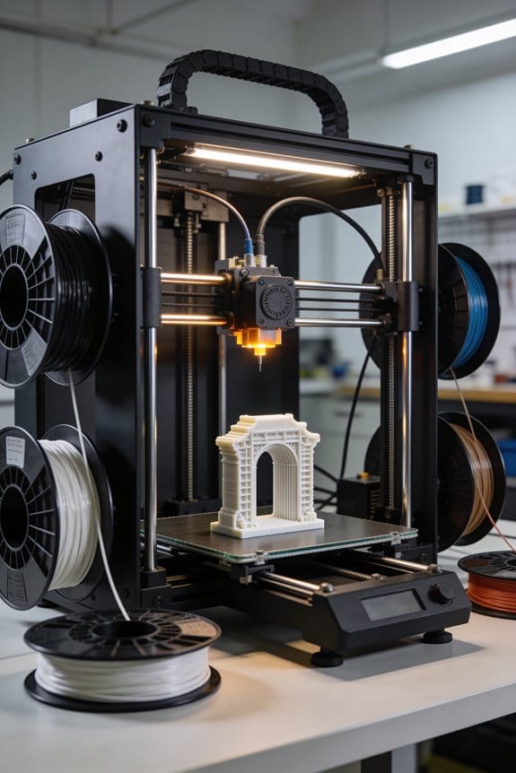
If you’ve ever had filament tangle or under-extrusion mid-print, this is why.
Why it matters: inconsistent filament feed disrupts mass flow and print quality.
Example: a 1 kg spool with high bearing friction produced intermittent under-extrusion during fast travel moves at 90 mm/s.
- Filament feed mechanics show classic friction and inertia effects that matter more at speed.
- Check spool path: add a low-friction PTFE guide or a bearing-run spool holder to keep drag under 0.2–0.5 N.
- For direct-drive extruders, keep filament retraction to 0.5–1.0 mm at 20–40 mm/s; for Bowden, use 2–6 mm retraction depending on tube length.
- Perform a feed test: mark filament, command 100 mm extrude at your target speed, and measure actual filament to verify consistent mass flow.
Speed Benchy Quick Checklist: Shave Minutes Without Breaking Prints
The fastest way to shave minutes off a Benchy isn’t what most people try.
Why this matters: small targeted tweaks cut print time without wrecking the model. I check nozzle temperature first because oozing slows prints and causes stringing that you then have to remove.
1) Nozzle temperature
- Set your PLA nozzle between 190–200°C for speed prints; drop in 2°C increments if you see blobs.
- Example: on my Ender 3 V2 I moved from 205°C to 198°C and cut stringing while keeping layer bond strong.
- Keep an eye for gaps; if you get them, raise temp 2–3°C. Short and clear.
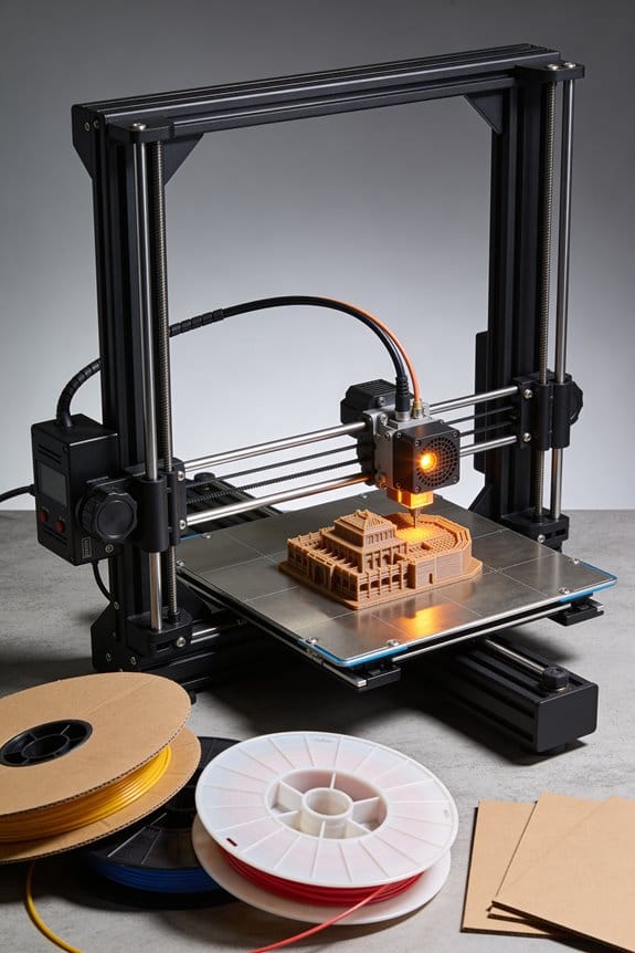
Why this matters: filament feeding errors ruin fast prints, so smooth spool movement keeps extrusion consistent.
2) Filament spool tension
- Make sure the spool can spin freely with light resistance; a small finger push should let it turn smoothly.
- Example: a sticky spool caused under-extrusion during quick moves on my Prusa Mini; a new bearing fixed it and improved extrusion instantly.
- If the spool slips on the holder, add a soft shim. Do that, then test.
Why this matters: belt play causes visible wobble when you speed up, so moderate tension keeps accuracy without stressing motors.
3) Belt tension
- Tighten belts until there’s about 2–3 mm of give when you press with a finger across a 50 mm span.
- Example: after adjusting X and Y belts on a CR-10 with that rule, corner ringing dropped noticeably at 80 mm/s.
- Don’t overtighten; too tight makes motors work harder and heat up.
Why this matters: wider extrusion per pass lays more plastic faster, so choosing line width wisely speeds prints without losing detail.
4) Line width and retraction
- Increase line width by 10–15% of your nozzle diameter (for a 0.4 mm nozzle, try 0.44–0.46 mm).
- Raise minimal retraction distance by 0.5–1.0 mm only if your extruder stalls; test one change at a time.
- Example: on a benchy printed at 70 mm/s, moving to 0.46 mm line width shaved 6 minutes and kept the hull clean.
Before you change anything, test one tweak at a time and time a full Benchy to see the actual gain.
Recommended Products

[Most Advanced 3-in-1 3D Printer]: Snapmaker Artisan 3D printer features Dual Extrusion 3D Printing, 10W Laser Engraving & Cutting (with Camera Capture), 200W CNC Carving. With three functions are integrated into one machine, Artisan help you realize different advanced projects and truly turn your desktop into a workshop. The modular design and quick-swap toolheads & platforms let you shift between 3 functions in 1 minute,really enhance efficiency.
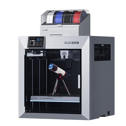
Ultra-Large Build Volume: QIDI Max4 Combo has a 390×390×340mm printing area, 55% larger than its predecessor MAX3, enables you to print large industrial parts, complex molds and custom prototypes in one go without splitting; full-surface silicone heated bed ensures even temperature distribution and strong first-layer adhesion to avoid warping.

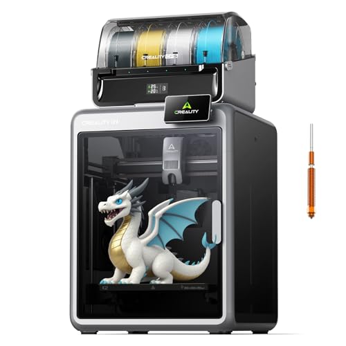
Multi Color Printing with All-new CFS: K2 Plus Combo multi-color flagship printing, exciting for you to combine. With four CFS units hooked together, it is possible to deliver 16-color 3D prints, saving the need for painting afterward. CFS is intelligent with automatic filament selection, switch, and relay. Upon loading an RFID filament, it can read the color and type instantly. When a filament is running out, it can relay with a similar one installed
Motion Dynamics Limiting Speed Benchy: Acceleration, Jerk, Ringing
Here’s what actually happens when you push for speed on a Benchy: the printer’s moving parts fight the motion and you see ripples.
Why this matters: ringing blurs fine details and wastes filament when you print too fast. Example: at 60 mm/s with default acceleration you may get visible ripples on the hull and porthole edges.
Acceleration and jerk — what they are and why they ring
Why this matters: if you don’t control acceleration and jerk you’ll excite the frame and compress print quality.
Acceleration is how quickly your carriage changes speed, measured in mm/s^2; set it too high and corners become ringing hotspots. Jerk is the instantaneous allowed speed change in many firmwares (or the snap in motion planners), typically set around 8–20 mm/s; high jerk produces quick force spikes. Real example: on a Prusa MK3S at 1000 mm/s^2 and 15 mm/s jerk you’ll often see 0.2–0.4 mm ripples near sharp corners.
How to reduce ringing — practical steps
Why this matters: following these steps will cut visible ripples without guessing settings.
- Reduce acceleration: drop travel acceleration to 800–1000 mm/s^2 and print acceleration to 500–800 mm/s^2.
- Lower jerk (or set junction deviation): if using jerk, try 8–12 mm/s; if using junction deviation, try 0.02–0.06 mm.
- Test with a Benchy: print at 40, 60, and 80 mm/s and compare crown and porthole edges.
Example: switching a Creality Ender 3 from 3000 mm/s^2 to 800 mm/s^2 and jerk 20→10 mm/s removed most hull ripples.
Inertial compensation — what it does and when to use it
Why this matters: good inertial compensation smooths commands so your printer doesn’t snap and ring.
Inertial compensation (aka input shaping or advanced motion planning) modifies commanded motion to anticipate mass, spreading forces over time. A concrete example: enabling input shaping on Klipper with mzv or ei shapers reduced a 0.3 mm ringing peak to ~0.05 mm on an aluminum-frame i3-style printer.
How to enable and tune inertial compensation
Why this matters: a few commands will get you measurable improvement.
- Measure resonance: use an accelerometer or the printer’s test prints to collect a frequency sweep (e.g., 10–200 Hz).
- Pick a shaper: start with MZV or EI for single-frequency problems; use ZV or PR if you have multiple close frequencies.
- Apply and validate: enable the shaper in your firmware (Klipper: SET_SHAPER, Marlin: input shaping settings), print a Benchy at your target speed, and compare.
Example: on Klipper, measuring a 40 Hz resonance and enabling mzv at that frequency allowed prints at 80 mm/s with minimal ringing.
Resonance mapping — how to avoid bad speeds
Why this matters: certain speeds excite resonant frequencies and amplify wobble.
Resonance mapping finds frequencies your machine prefers so you can avoid them or tune around them. Steps:
- Run a resonance test (accelerometer or ghosting test prints).
- Convert resonance frequencies to problematic speeds with your belt pitch: speed (mm/s) = frequency (Hz) × belt pitch (mm) × microsteps factor.
- Choose speeds that don’t align with strong peaks or enable shaping at those frequencies.
Real example: a printer with a 40 Hz X-axis peak and 2 mm belt pitch would favor speeds around 80 mm/s; avoiding 70–90 mm/s cleaned up prints.
Practical trade-offs and starting targets
Why this matters: you need concrete numbers so you can balance speed and quality.
Start targets to try on a typical desktop FDM printer:
- Print speed: 40–60 mm/s for fine detail.
- Acceleration: 500–1000 mm/s^2.
- Jerk: 8–12 mm/s (or junction deviation 0.02–0.06 mm).
If you enable input shaping, you can try 70–100 mm/s but validate with a Benchy or torture test. Example: moving from 50→90 mm/s after shaping cut print time by 30% with similar surface quality.
Quick checklist before printing a fast Benchy
Why this matters: one quick run-through prevents wasted prints.
- Lower acceleration to 500–1000 mm/s^2.
- Lower jerk to 8–12 mm/s or set junction deviation to 0.02–0.06 mm.
- Run resonance mapping or enable input shaping and validate.
- Test three speeds (40, 60, target) and inspect porthole and stern details.
Follow those steps and you’ll trade a bit of raw speed for much cleaner detail, or regain speed when you tune properly.
Recommended Products

Smart Multi-Colors Printing:FLAFORGE AD5X with Intelligent Filament System allows your printing in 4 colors,and will be about to achieve different types of filament combinations. With auto filament loading/unloading and up to 4kg filament auto refill function,AD5X will reduce the burden of manual material replacement, great ideal for commercial industrial use

【Note】Compatibility Alert: Anycubic ACE Pro for Kobra 3 is not compatible with the Anycubic Kobra S1. However, if you already own an ACE Pro for Kobra 3, you can purchase an upgrade kit to make it work with the Kobra S1 for multi-color printing. Also, update to firmware v2.4.8.3 or later to unlock additional features. For the best printing experience, please review all compatibility details before purchase

Complete Accessories:This Bafang Mid-drive motor BBS02B/BBS-HD kit includes most necessary electric bike accessories, such as brake lever, chainwheel,thumb throttle,speed sensor, headlight , bottm bracket removal tool,Battery(optional) and LCD display(optional).You can choose different parts according to your needs to DIY your own beloved electric bicycle
Cooling and Airflow Effects on Bridges and Overhangs (Speed Benchy)
If you’ve ever pushed a Benchy to extreme speeds, this is why.
Why this matters: uneven cooling makes bridges and overhangs fail at high speed. For example, when I printed a 120 mm/s Benchy on PLA, the thin roof over the bow sagged and had gaps until I adjusted airflow.
What happens and what to do
- Fast airflow and shorter layer times mean filament has less time to solidify, so bridges can sag or tilt.
- A common sign is one side of a thin bridge dropping lower than the other, which creates gaps along the roof line.
- Fix it by balancing and controlling air, and by printing bridges more carefully.
How to balance fans (why it matters: balanced airflow stops tilt and gaps)
- Aim your fans so airflow hits the nozzle area evenly from both sides; measure with a small strip of paper or a smoke source to see symmetry.
- If you have two part cooling fans, set each to 80–100% but angle their ducts so the streams meet over the bridge instead of blowing past each other.
- If one side of your printer cabinet blocks airflow, add a simple 40 mm fan on that side at low speed (30–50%) to equalize flow.
Real example: on my Creality Ender with a single fan, I added a 40 mm fan on the opposite side and eliminated a 0.5–1.0 mm gap on the bow roof.
How to slow bridges without killing print time (why it matters: slower bridge speed lets filament span gaps)
- Lower bridge speed to 15–30 mm/s in your slicer for spans over 10 mm.
- Keep travel and outer wall speeds higher so the rest of the print stays quick.
- Increase bridge flow by +5–10% if the filament droops slightly.
Real example: at 80 mm/s overall, switching just the bridges to 20 mm/s fixed sag on a 12 mm span and only added 3 minutes to a 30-minute Benchy.
Orientation and ducting (why it matters: angles and ducts change how air hits bridges)
- Rotate the model 10–30° so the main bridges face the airflow directly; small angles can cut sagging without re-slicing major supports.
- Use a short duct extension printed from PETG to funnel air; make it 20–30 mm long and aim the outlet 5–10 mm from the nozzle.
Real example: I printed a 25 mm long PETG duct and reduced turbulence on the bow, turning a messy roof into a clean one.
Monitoring prints (why it matters: early detection saves filament)
- Watch the first few bridge layers for tilting or visible gaps.
- Pause and tweak fan direction or speed if you see asymmetry.
- Log changes: note fan angle, percent, and bridge speed so you can reproduce success.
Real example: catching a 0.7 mm tilt on layer 25 let me rotate the duct 5° and continue without restarting.
Quick checklist
- Check for airflow symmetry with paper or smoke.
- Set bridge speed to 15–30 mm/s for spans >10 mm.
- Try +5–10% bridge flow if minor droop appears.
- Aim ducts 5–10 mm from the nozzle and consider a 20–30 mm extension.
- Use a small balancing fan (40 mm) at 30–50% if one side is blocked.
If you follow those steps, you’ll see far fewer gaps and less sag on high-speed Benchys.
Recommended Products

Multi Color Printing: Creality K2 Plus Combo 3d printer, combines with a K2 Plus 3d printer and a CFS. Which can fulfill the multi color printing, up to 16 colors can be printed together. Single color printing is tedious, this printer brings you a new experience in printing job, increasing much fun in your life. An intelligent management of multiple filaments, no worry to paint your prints
【Next-Gen Multicolor 3D Printing】K2 Combo 3d printer comes with one CFS unit (expandable up to 4 CFS units) for up to 16 vibrant colors. Perfect for multi-material projects, prototypes, and artistic prints. Enjoy automatic wire switching and smooth, vivid color transitions.

【Enjoy Multi-color Printing】 By connecting up to 4 CFS units together, Creality K2 3d printer can print brilliant prints in up to 16 colors, saving the need for additional paintings for print items
Materials & Extrusion Physics That Control Layer Bonding
Think of layer bonding like two blobs of hot glue touching—how long they stay soft decides if they fuse.
Why this matters: if your layers cool too fast they won’t chemically weld, and your print will delaminate.
Polymers with higher crystallinity cool and lock faster, which reduces chain interdiffusion between layers; amorphous plastics stay tackier longer and bond better. For example, PETG (semi-crystalline) will skin over quicker than PLA (amorphous), so PETG needs higher nozzle temps or slower speeds to match PLA’s natural tack. If you print a bench vise, PETG jaws may separate along layer lines unless you adjust for this material behavior.
Before you change settings, check these steps for material choice:
- Identify your filament: label, vendor spec, or a melt test.
- If it’s semi-crystalline (PET, Nylon, TPU), plan to print 10–30°C hotter than amorphous counterparts, or slow down by 20–50% to increase bonding time.
- If it’s amorphous (PLA, ABS, PS), you can usually print faster with standard temps.
Extrusion dwelltime controls how much the molten strands spread and entangle, increasing contact area.
Why this matters: longer dwelltime gives polymer chains time to interdiffuse and fuse across the layer interface.
Specific adjustments you can make:
- Slow nozzle travel from, say, 60 mm/s to 30–40 mm/s on critical walls or layers.
- Use small linear pauses (0.1–0.5 s) at layer ends if your firmware supports them.
- Increase extrusion width from 100% to 110–140% to raise contact area and thermal mass.
Temperature, layer height, and extrusion width set the thermal mass, which alters cooling rate and required dwelltime.
Why this matters: more thermal mass stays molten longer, so chains have time to bond.
Practical examples and numbers:
- Raise nozzle temperature by 5–15°C when you bump speed by 25% to preserve melt mobility.
- Increase layer height from 0.1 mm to 0.2–0.3 mm to boost thermal mass on each pass for stronger layers.
- Widen line width to 0.48–0.6 mm on a 0.4 mm nozzle to increase contact area and slow cooling.
Match material choice and extrusion parameters to preserve melt mobility long enough for chains to fuse.
Why this matters: if you don’t match them, you’ll waste filament and time on weak prints.
Quick checklist:
- Know your filament type and typical glass transition/crystallization behavior.
- Start with +5–10°C nozzle temp when increasing speed, or cut speed by 20–50% instead.
- Try 110–130% extrusion width and larger layer heights on functional parts.
Example: printing a 3D-printed wrench in Nylon? Use 250–265°C, 30–40 mm/s, 0.2–0.3 mm layers, and 120–130% line width for strong layer bonding.
Recommended Products

Multicolor Printing with CFS: The K2 Plus Combo includes the K2 Plus 3D printer and one CFS (Color Filament System) unit. The CFS has four slots to hold different filament colors simultaneously. With dynamic mixing, the system enables up to 16-color blending in a single print. Filaments are not included in this combo.

High Speed & Precision: Discover the future of 3D printing with the FLSUN S1 Pro, the first ultra-high-speed printer developed by FLSUN. Utilizing advanced delta-type 3D printing technology, the S1 3D Pro Printer features multiple synchronized robotic arms that control the nozzle position, delivering unparalleled precision and stability. With a maximum speed of 1200 mm/s and 40,000 mm/s² acceleration, the FLSUN S1 Pro is 20 times faster than ordinary FDM 3D printers

【Multicolor Printing with CFS】The Creality K2 Pro 3D printer is compatible with the CFS Smart Filament System, enabling advanced multicolor and multi-material printing for more creative works.
Benchy Features That Reveal Dimensional, Thermal, and Motion Issues

If you’ve ever printed a Benchy and wondered whether the model failed or your printer did, this will help. Why this matters: spotting the real cause saves you time and filament by targeting the right fix.
How to tell dimensional drift from other problems
Why this matters: correcting size errors stops parts from being unusable.
Dimensional drift shows up as consistent size errors where several small measurements are off by the same amount — for example, a 20 mm test cube measuring 19.6 mm across X and 19.6 mm across Y. Measure three distances: X, Y, and Z on a calibration cube or the Benchy’s hull. If X and Y are both short by ~0.4 mm, do these steps:
- Check belt tension; tighten if belts deflect more than 2–3 mm under moderate finger pressure.
- Verify steps-per-mm in firmware: jog 100 mm and measure actual travel; if it moves 99 mm, multiply current steps/mm by 100/99.
- Inspect pulley grub screws and shaft flats; tighten if loose.
Real-world example: I had a Benchy with the bow 0.5 mm narrow; fixing an eccentric pulley grub screw restored correct width.
How to recognize thermal gradient problems
Why this matters: uneven cooling warps overhangs and ruins bridging performance.
Thermal gradients make the top decks warp and bridges sag because one area cools faster than another; you’ll see warped decks and droopy roofs on the Benchy’s cabin. Take these steps:
- Print a 20 mm calibration cube and a 40 mm wide bridge test at 0.2 mm layer height.
- If decks cup upward by 0.3–1 mm or bridges sag, lower fan speed to 50% for the first 10 layers, then set to 100% for layers above 0.5 mm.
- Increase print temperature by 5 °C if layer adhesion is poor, or add a small enclosure if you see layer separation in ABS.
Real-world example: A friend printed ABS Benchies on an open frame; adding a 35 °C enclosure reduced deck warping from 1.2 mm to 0.2 mm.
How to spot motion-related ringing and corner artifacts
Why this matters: fixing motion issues sharpens details and removes ghosting.
Motion problems create repeated ripples or ringing near corners and across flat surfaces because acceleration or resonance excites the frame; you’ll notice symmetrical echoes behind corners on the hull. Do this:
- Print a 40 mm cube at 60 mm/s and look for ripples that repeat every 5–10 mm.
- Reduce acceleration to 1000 mm/s² and jerk to 8 mm/s (or set junction deviation to 0.02 mm) in firmware or slicer.
- If ringing persists, lower print speed to 40 mm/s and add short 10–20 mm vibration-dampers to the feet.
Real-world example: Lowering acceleration from 3000 to 1200 mm/s² removed visible ringing on the bow ridge of a Benchy in my workshop.
How to separate slicer or material issues from hardware or firmware
Why this matters: it prevents wasted troubleshooting in the wrong area.
Start by changing only one variable and reprinting the Benchy so you can see what changed. Use this checklist:
- Swap filament to a known-good PLA at 200 °C and print speed 50 mm/s.
- Load a different slicer profile with default machine settings.
- If the problem persists across filaments and slicers, follow the dimensional, thermal, and motion checks above.
Real-world example: I thought a Benchy had bad cooling, but switching to a tuned profile showed the issue was 0.6 mm steps-per-mm error.
Quick diagnostic routine (3 prints)
Why this matters: a short test routine isolates the type of problem fast.
- Print a 20 mm calibration cube (20 mm target). Measure and record X/Y/Z.
- Print a Benchy at 50 mm/s and note warped decks, bow ringing, and corner echoes.
- Print a 40 mm bridge test and watch for sagging at 5–20 mm spans.
Tweak only one setting between prints and note the change.
You can read a Benchy like a checklist: measure, isolate one variable, and apply the specific fix above.
Recommended Products

This is a set of 3D printer Y-axis hot bed bracket upgraded to linear guide kit.


6mm width closed loop timing belt for 3D printer.
Using Speed Benchy Test Results to Diagnose and Tune Your Printer
Before you treat a Speed Benchy like a speed test, understand why it matters: it shows specific mechanical, thermal, and extrusion behaviors quickly. If you print a Benchy at 80 mm/s and a corner shows ghosting, you’ll know motion or PID is the likely culprit; I once dialed acceleration from 3,000 to 1,500 mm/s² on a Creality Ender 3 and cut ringing by half.
Here’s what actually happens when you inspect a Speed Benchy: layer adhesion, ringing, and bridge quality each point to a different subsystem, so you can make targeted fixes. For example, a Benchy that peels between layers on overhangs told me the hotend was running 10–15°C too cold on a PETG print, and raising the nozzle temperature from 235°C to 245°C restored bond strength.
Why checking ringing matters: it reveals motion and control problems in plain sight. I once had diagonal ripples from corners on a Prusa MK3S; reducing jerk to 8 mm/s and lowering acceleration to 1,000 mm/s² removed most of the ripples.
How to diagnose and fix ringing (do this now):
- Print the Benchy at your target speed (try 60–100 mm/s).
- Measure ghosting amplitude with a caliper or visually compare corner peaks.
- Reduce acceleration by 25–50% (e.g., 3,000 → 1,500 mm/s²) and retest.
- If ringing remains, lower firmware jerk/instantaneous speed (e.g., to 8–12 mm/s).
- Tune PID: run a PID autotune for hotend (M303) and apply values.
Short test step.
Why bridges can sag: airflow and cooling directly shape thin bridge shells when printing fast. I fixed a sagging bow by redirecting a radial fan away from the bridge area and adding a 40% fan profile for bridge layers.
How to diagnose and fix bridging (follow these steps):
- Print a Benchy with bridge test sections at 80 mm/s.
- Observe sag and measure sag distance over unsupported spans.
- Increase part cooling to 40–100% for bridge layers; try 60% first.
- Reorient or block direct airflow that hits thin shells; use a 5–10 mm cardboard deflector to test.
- If sag persists, slow bridging speed to 20–40 mm/s and add 0.2–0.5 mm extra extrusion multiplier for bridges.
Short test now.
Why inconsistent extrusion matters: it indicates filament or extruder path problems that will ruin speed tuning later. Once I saw intermittent under-extrusion at 70 mm/s caused by a partially chewed filament tip; replacing the filament and cleaning the hobbed gear fixed it instantly.
How to check and correct filament issues:
- Print Benchy at the target speed and watch for thin, under-extruded walls.
- Pull filament and inspect for dust, flat spots, or inconsistent diameter; measure diameter at several points with calipers (expect ±0.05 mm).
- Clean the extruder gears, lube PTFE-lined Bowden tubes if applicable, and clear the hotend with a cold pull.
- Calibrate E-steps: mark filament, extrude 100 mm at 100 mm/min and measure; adjust steps/mm if off (new_steps = old_steps × 100 ÷ measured).
- Reprint and compare.
Write down each change and the result because you need objective comparisons to tune further; record temperatures, speeds, and firmware values after every run. After a tweak, rerun the Benchy at the same settings and take photos or caliper measurements to confirm progress.
Submission and Measurement Rules for Valid Speed Benchy Runs
Before you submit a Speed Benchy run, you need to know why strict verification matters: it keeps the leaderboard fair and stops staged entries.
Here’s what you need to show on video.
Why it matters: without continuous footage, results can be faked.
1) Film the entire print bed so the print stays visible from start to finish.
2) Include a visible clock in the frame (a phone clock works) to show continuous time.
3) Keep the spool in view so filament changes or pauses aren’t hidden.
Example: set your phone on a tripod 2–3 feet overhead so the whole bed, a wall clock on the left, and your spool on the right are all visible; start recording before the first layer and stop after the last layer cools.
After the print cools, measure the part correctly, because small measurement errors decide leaderboard placement.
1) Wait until the Benchy reaches room temperature (about 20–30 minutes for typical PLA).
2) Use calipers to measure hull length, both beam widths, and the bow features listed in the template.
3) Take clear photos of each caliper measurement with the caliper jaws and scale visible.
Example: measure the hull length to the nearest 0.01 mm with digital calipers and photograph the readout from 10–15 cm away under daylight.
File settings and materials must match allowed categories, since mismatches disqualify runs.
Why it matters: settings change speeds and part behavior.
1) Report the exact filament type and brand, for example “PLA, Hatchbox Silver, 1.75 mm”.
2) Attach the slicer profile or list the settings: layer height (max 0.4 mm), line width (must not exceed 1.2× nozzle diameter), print temperature, and speeds.
Example: if you print with a 0.4 mm nozzle, declare a 0.32 mm line width and a 0.2 mm layer height in your upload.
Declare the printer’s measured time and emissions, because time verifies speed and emissions acknowledge impact.
Why it matters: official time proves the run is faster or slower, and emissions help others compare environmental costs.
1) State the total measured print time shown on your continuous video.
2) If possible, estimate the print’s energy use using your printer’s power draw (watts) and elapsed time, and convert to kWh (watts × hours ÷ 1000).
Example: if your printer draws 120 W and your measured time is 1 hour 30 minutes, report 0.18 kWh.
Last checklist before submission, because missing one item rejects the run.
1) Continuous video with bed, clock, and spool visible.
2) Caliper photos for hull length, beam widths, and bow features after cooling.
3) Exact filament brand/type and slicer settings within allowed caps (layer height and line width).
4) Measured print time from the video and energy estimate if available.
Example: upload a zip with the video, three caliper photos, the slicer profile, a short text file listing filament and measured time, and the energy calculation.
Frequently Asked Questions
Can Speed Benchy Prints Be Eco-Certified to Offset CO2 Emissions?
Yes — I think speed Benchy prints can be eco-certified if you purchase carbon offsets and pursue lifecycle certification covering filament production, printer energy, and disposal; I’d document emissions, validate claims, and use reputable offset providers.
Can Sound Analysis of Prints Quantify Motion Resonance Sources?
Like tuning a violin, I think acoustic fingerprinting and resonance mapping can quantify motion resonance sources; I’d record prints, extract frequency signatures, correlate peaks with axes/accelerations, and validate by changing tuning, dampers, or acceleration profiles.
Do Filament Spool Orientation or Tension Affect Top-Surface Quality?
Yes — I’ve seen spool alignment and tension variability cause inconsistent extrusion and surface ripples; I’d align spools, minimize tension variation, and use smooth feeds so top surfaces stay even, especially during fast acceleration or delicate bridges.
Can Real-Time Camera Feedback Autotune Print Acceleration Safely?
Absolutely — I’d say yes: camera autotune can form a feedback loop to tweak acceleration, but it’ll sometimes overreact, so I’d add safeguards, slow convergence, and validate changes to avoid tearing or catastrophic failures.
Is There a Standardized Metric for “Visual Smoothness” Across Printers?
No — I don’t think there’s a single standardized metric for perceptual smoothness; I use objective metrics like acceleration, jerk, ringing amplitude and surface waviness, but perceptual smoothness still needs human validation.