As an Amazon Associate, we earn from qualifying purchases. Some links on this site are affiliate links at no extra cost to you. Our recommendations are based on thorough research and editorial judgment.

Understanding the Photochemistry of UV Resin Polymerization

You’ve mixed a UV resin, shined your lamp on it, and the surface cured while the rest stayed tacky — why didn’t it finish?
You can’t tell from a quick cure whether the photochemistry or the setup is to blame. Most people assume a stronger lamp or longer exposure always fixes tacky parts, but that overlooks initiator type, oxygen inhibition, and spectral mismatch.
This article will show you how to diagnose whether radicals, acids, or oxygen are stopping your cure and how to match initiator absorbance to your lamp, dose, and formulation so your resin fully hardens and reaches the mechanical properties you expect.
You’ll get clear tests to run and practical fixes to try.
It’s easier than it looks.
Key Takeaways
If you’ve ever wondered why your UV resin sometimes cures unevenly, this explains the basics so you can fix it.
Why it matters: understanding the photochemistry helps you choose the right lamp and additives so your parts cure reliably. In a typical 3D-printing bench project, for example, a tiny ring cured unevenly because the lamp peak didn’t match the photoinitiator.
1) What do photoinitiators do?
– Photoinitiators absorb UV light and immediately make reactive species (either radicals or acids) that start polymer chains.
Example: when you shine a 405 nm LED on a resin with a radical initiator, the initiator splits and you see tack-free gel in seconds.
Why it matters: if your photoinitiator doesn’t absorb the lamp wavelength, nothing will start. In practice, test a 1 mm test cure: 5–10 seconds under your lamp and check tack.
2) How do Type I photoinitiators work?
– Type I photoinitiators cleave under 365–405 nm LEDs and give fast radical cures; match the lamp peak to the photoinitiator absorbance.
Example: use TPO-L or Irgacure 819 with a 405 nm diode for quick desktop printer layers.
Why it matters: matching wavelengths lets you cure layers in seconds rather than minutes. Try 0.5–3% w/w loading; 1% is a good starting point for 0.2–0.5 mm layers.
3) Why do radical systems stall at the surface?
– Radical systems polymerize rapidly but suffer oxygen inhibition at the surface because oxygen scavenges radicals.
Example: a flat cast panel cured in air has a sticky top layer after 10 seconds, but the bulk is hard.
How to fix it:
- Add an amine synergist (1–3% w/w).
- Cure under nitrogen or argon if you can.
- Increase exposure time by 20–50% for the topmost 0.1–0.2 mm.
4) What do cationic systems do differently?
– Cationic systems generate acids that enable dark cure and deeper penetration, but they are moisture-sensitive and slower.
Example: a deep pot-coating cured overnight because the acid kept polymerizing after the lamp was off.
Why it matters: use cationic chemistry when you need post-cure in shadowed regions, but keep humidity below ~40% and expect longer full cure times (hours).
5) How does formulation control performance?
– You control shrinkage, toughness, and cure depth with oligomer molecular weight, monomer content, and photoinitiator loading (0.5–3% w/w recommended).
Example: swapping a low-molecular-weight monoacrylate for a difunctional oligomer cut shrinkage and made the part less brittle.
Quick practical steps:
- Identify your lamp peak (e.g., 365 nm or 405 nm).
- Choose a photoinitiator that absorbs that peak (TPO-L/819 for 405 nm; BAPO or others for 365 nm).
- Start PI at 1% w/w and adjust between 0.5–3% based on test cures.
- If surface tack occurs, add 1–3% amine synergist or purge with nitrogen.
- For deep or shadowed cures, use cationic systems and control humidity <40%.
Follow these checks and you’ll get fewer failed prints and more predictable cures.
UV Resin Photochemistry: Photoinitiators and How UV Starts Polymerization
If you’ve ever watched a 3D print cure under a UV lamp, this is why.
Why it matters: knowing how a photoinitiator works helps you pick the right one so your resin cures fast and evenly. Picture the photoinitiator as the spark that turns liquid resin into solid plastic. For example, when you cure a small SLA print with a 405 nm lamp, the right initiator makes the layers bond cleanly instead of leaving sticky spots.
How photophysics works, simply: photoinitiators absorb UV photons, jump to excited states, and then either break apart or transfer energy to form reactive species that start chain growth. A common case is a Type I initiator (like TPO) that cleaves into two radicals when hit at 365–420 nm; a visual example is a thin 1 mm test stripe curing within 5–10 seconds under a 405 nm LED. Another case is a Type II initiator (for example, benzophenone with a co-initiator) that needs a hydrogen donor to produce radicals, so you’ll see slower surface cure unless you add the co-initiator.
Why solubility matters: if the initiator won’t dissolve, light absorption and radical or acid generation are uneven, reducing cure efficiency. For instance, if you sprinkle 1% w/w crystalline initiator into a viscous resin and don’t dissolve it, your 50 µm layers may show streaks after 30 seconds of exposure.
How to make practical choices (steps):
- Match absorption to your lamp:
- Measure or check the lamp peak (e.g., 365 nm, 385 nm, 405 nm).
- Choose an initiator with strong molar extinction at that wavelength (TPO for 385–405 nm, Irgacure 819 for 365–385 nm).
- Start with 0.5–3.0% w/w for acrylate systems; adjust by 0.5% increments based on cure speed and depth.
- For thick parts (>2 mm), increase by 0.5–1% and verify through-thickness cure times.
- Pre-dissolve in a reactive diluent or warm the resin to 40–50 °C if needed.
- If the initiator shows cloudiness at your working temperature, lower its loading or pick a more compatible initiator.
- Use lower concentration (0.5–1%) for fine detail and high-resolution prints to avoid overcuring surface areas.
- Use higher concentration (2–3%) for thick, fast cures but expect shallower light penetration.
- Cure a 1 mm and a 3 mm disc at your standard exposure; record tack-free time and hardness after 24 hours.
- Use an inert atmosphere (nitrogen purge) or a thin glass/foil cover, or increase lamp intensity to >50 mW/cm² to outrun oxygen.
- For coatings and inks, cure in 5–60 seconds with 10–50 mW/cm²; for thicker parts, cure in stages.
- Keep moisture low: store and handle resins below 50% relative humidity and dry substrates when possible.
- Expect full cure over hours at room temperature; accelerate with gentle heat (40–80 °C) for 30–60 minutes.
- Choose radical systems for very fast surface cures like inks and thin coatings when you need seconds-level throughput.
- Choose cationic systems for low-shrinkage, deep cures like structural epoxies or when you want post-cure to improve mechanical stability.
- Color: some photoinitiators yellow under light. If color matters, test your initiator under your exact lamp and substrate; use phosphine oxide types for lower yellowing.
- Water with cationics: avoid water contact; dry substrates or use desiccant storage.
- Oxygen with radicals: use nitrogen purge, a laminated cover, or tack-free formulations; test cure at your intended lamp intensity.
Real-world example: when switching from a 365 nm mercury lamp to a 405 nm LED on a tabletop printer, users switching from Irgacure 2959 (poor 405 nm absorbance) to TPO at 1.5% w/w saw cure times drop from 20 seconds per layer to 8–10 seconds, and the surface finish became more consistent.
Remember: your lamp wavelength, initiator absorption, concentration, and solubility all interact to determine how fast and how completely your UV formulation crosslinks under exposure. Test empirically with those steps and record the exact exposure times and temperatures you used.
Radical vs. Cationic Polymerization: Mechanisms and Practical Differences
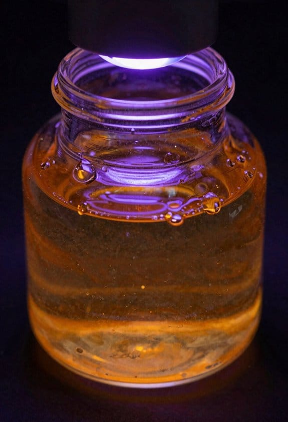
The difference between radical and cationic polymerization comes down to how the reaction starts and whether it keeps going after you turn the light off.
Why this matters: choosing the wrong system wastes time and gives bad parts. For radicals, a common real-world example is UV-cured nail polish that dries in seconds under a lamp.
How radical polymerization starts, grows, and finishes — and what you do
Why it matters: radicals stop at the surface if oxygen is present, so your cure can fail unless you control air.
1) Initiation: photoinitiators (e.g., benzoin ethers or acylphosphine oxides) split under UV into free radicals that add to acrylate double bonds.
2) Propagation: chains grow very fast — reactions complete in seconds to minutes under 365–405 nm lamps at typical intensities of 10–50 mW/cm².
3) Termination: oxygen quenches radicals at the surface, creating a sticky tacky layer unless you remove oxygen.
Steps you can take:
Example: when printing a UV inkjet label, you’ll run into a tacky edge unless you add a nitrogen hood or use an oxygen-tolerant formulation with amine synergists.
How cationic polymerization starts, grows, and finishes — and what you do
Why it matters: cationic systems keep curing after the light goes off, so you get deeper, stress-relieved parts without continuous exposure.
1) Initiation: on exposure, photoinitiators (e.g., diaryliodonium or triarylsulfonium salts) generate strong acids.
2) Propagation: those acids open epoxy rings and the chain grows more slowly than radicals, but the acid is *persistent*, so curing continues in the dark (known as dark cure).
3) Termination: the process is self-limiting only when the acid is neutralized or consumed; water will terminate the active species.
Practical steps:
Example: when bonding an epoxy lens, you’ll get better final clarity and lower shrinkage if you let the part post-cure for several hours, or heat at 60 °C for 30 minutes.
Which to pick for common jobs
Why it matters: picking based on the property you need saves rework and material cost.
Example: for a quick graphic decal cured under a handheld lamp, use acrylates; for a bonded composite part that must resist deformation, use a cationic epoxy and plan a 1–24 hour post-cure.
Practical warnings and quick fixes
Why it matters: a small mistake can ruin batches.
Example: if your clearcoat yellows after storage, swap to a less yellowing initiator and test at 1,000-hour light exposure to confirm.
Quick checklist before you run a job
Why it matters: these five checks prevent common failures.
1) Lamp spectrum and intensity match your photoinitiator.
2) Substrate moisture <50% RH for cationics.
3) Oxygen control (nitrogen or cover) for radical surface cures.
4) Plan post-cure for cationics: time or 40–80 °C heat.
5) Test for color change under your production lamp.
That’s the practical difference: radicals are fast but sensitive to oxygen; cationics are slower, keep curing, and hate water.
Recommended Products

Low Odor&Hardness: LET'S RESIN upgrade UV resin is developed and produced safely, using high-quality materials, after long testing and improvement. The reactive diluent is added to reduce volatile components, minimize odor, and allow you to use it more confidently. The UV resin has a shrinkage rate below 2% and cured resins up to 85D with excellent hardness, durability, and scratch resistance. This UV resin kit is perfect for making beautiful necklaces, earrings, pendants.

Low Odor&Hardness: LET'S RESIN upgrade UV resin is developed and produced safely, using high-quality materials, after long testing and improvement. The reactive diluent is added to reduce VOC volatile components, minimize odor, and allow you to use it more confidently. The UV resin has a shrinkage rate below 2% and cured resins up to 85D with excellent hardness, durability, and scratch resistance. This UV resin kit is perfect for making beautiful necklaces, earrings, pendants.

Professional UV Resin Light&Faster Curing:LET'S RESIN UV Light customized professional UV light has 18pcs double light source lamp beads, uniform distribution, compared with other small power UV lamps, has stronger curing effect, faster-curing speed and evenly curing effect.
How Oligomers and Monomers Build the Crosslinked Network
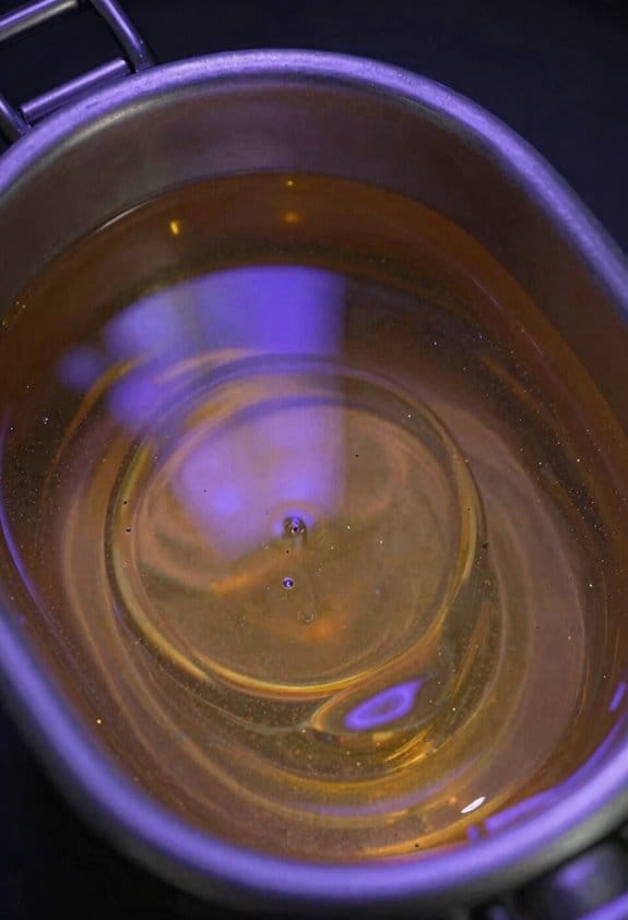
Here’s what actually happens when you turn liquid resins into a cured network: it changes how the material behaves, so you can get the toughness or flexibility you want.
When you mix oligomers and monomers, you’re combining two roles. Oligomers are the higher–molecular–weight chains that become the backbone of your cured material; they set bulk properties like toughness and flexibility. For example, using a 2,000–5,000 g/mol oligomer in a coating will give you a noticeably tougher film than a 500 g/mol oligomer. Pick an oligomer in that range for durable parts.
Why this matters: the balance between chain length and crosslinks controls shrinkage, hardness, and solvent resistance. In a clear coating used on furniture, too many short monomers can cause visible shrinkage and brittleness; more oligomer content reduces that while keeping flexibility.
How monomers work and a quick step you can follow:
- Use monomers as reactive diluents and crosslinkers — they lower viscosity so you can apply the formulation and then form bridges between oligomer chains.
- Target 10–30% reactive monomer by weight for many coatings to get good flow without excessive shrinkage.
- Choose monomers with functionality 2 or 3 (di- or tri-functional) to control crosslink density.
Real-world example: if you’re formulating a UV-cured varnish for tabletops, start with 70% oligomer (3,000 g/mol urethane acrylate), 20% mono- or difunctional acrylate monomers to adjust viscosity, and 10% photoinitiator and additives.
The difference between radical and cationic routes comes down to the reactive species and speed, and you should pick the route based on your needs. Radical polymerization uses free radicals that add monomers rapidly to grow chains and create crosslinks fast; it’s great when you need quick cure times under UV. Cationic polymerization uses positively charged species that open epoxide rings or add to double bonds more slowly, and it keeps reacting in the dark after light is removed.
Why this matters: cure mechanism affects pot life, depth of cure, and sensitivity to oxygen. For example, a radially cured floor coating can tack at the surface if oxygen inhibition isn’t addressed, whereas a cationic epoxy varnish will continue curing in shadowed corners after the light goes off.
How network topology controls final properties:
- Increase crosslink density to raise hardness and solvent resistance.
- Reduce crosslink density (more flexible links or longer oligomers) to raise toughness and reduce shrinkage.
- Monitor gel point: faster gelation traps stresses and increases shrinkage.
Practical example: to improve solvent resistance on a printed circuit board coating, increase tri-functional monomer content by 5% and measure solvent uptake; you should see a measurable drop in swelling within 24 hours.
A few actionable rules of thumb you can use:
- Start with 60–80% oligomer for structural coatings, 30–50% for flexible films.
- Use 10–30% reactive monomer to tune viscosity and crosslinking.
- For fast UV cure choose radical systems and add an amine synergist if oxygen inhibition is an issue.
- For deep or post-cure in shadowed areas choose cationic systems; they keep curing after irradiation.
Pick one variable at a time when you test formulations.
Choosing Resins, Monomers, and Photoinitiators for Performance Targets
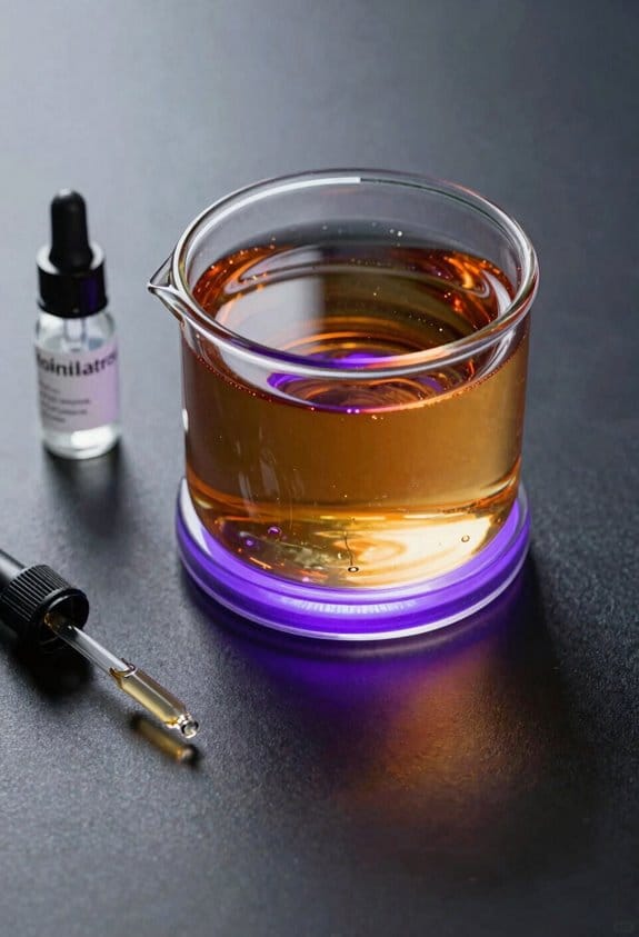
Before you choose resins, monomers, or photoinitiators, know what performance you need and why it matters: it determines toughness, clarity, cure depth, and regulatory risk.
Pick a resin molecular weight to hit mechanical and processing targets. Higher molecular weight oligomers (5–20 kDa) give you toughness and lower shrinkage; lower molecular weight oligomers (200–1,000 Da) improve flow and reduce viscosity so you can coat thin layers. Example: for a 1 mm structural print, use a 5–10 kDa urethane acrylate oligomer to resist fracture. Steps:
- Measure target viscosity (cP) for your process.
- Choose oligomer MW to get within that viscosity range.
- Verify mechanical properties (tensile strength, elongation) on sample prints.
Choose monomers by functional group to control crosslink density and viscosity, because this directly changes stiffness and cure behavior. A di-functional acrylate (e.g., 1,6-hexanediol diacrylate) increases rigidity without making the mix too viscous; a tri-functional monomer (e.g., trimethylolpropane triacrylate) pushes crosslink density and raises modulus but increases brittleness. Example: if you want a rubbery seal with 100–300% elongation, use 10–20% mono-functional acrylate plus a low fraction (5–10%) of tri-functional monomer. Steps:
- Decide desired modulus and elongation.
- Select mono/di/tri proportions to tune crosslink density.
- Test cure and adjust ratios by 5% increments.
Pick photoinitiators by initiation type and absorption to match your light source because that decides cure speed and depth. For 385–405 nm LED lamps pick Type I acylphosphine oxides (e.g., TPO or BAPO) for fast radical starts and deep cure; for 250–350 nm choose benzoin ethers or alpha-hydroxyketones. Photobleaching matters: TPO bleaches and improves transparency after cure, while BAPO can leave yellowing if overdosed. Example: for clear dental appliances cured with a 405 nm LED, use 1–2 wt% TPO to get 1–2 mm depth of cure with minimal yellowing. Steps:
- Match PI absorption to lamp spectrum.
- Start at 0.5–2.0 wt% and measure depth of cure.
- Adjust for clarity and cure speed.
Check regulatory compliance early because some monomers and photoinitiators face restrictions and that affects usable ingredients. For example, some acrylates are skin sensitizers and require hazard labels or substitution in consumer products. Example: selling a nail product? Avoid high concentrations of known sensitizers and keep documentation of SDS and exposure limits. Steps:
- List all ingredients and check SDS and REACH/EU/US limits.
- Substitute restricted components before scale-up.
- Keep compliance records with batch formulations.
Balance cure speed, mechanics, and optics by iterating with small batches because you’ll need trade-offs. If you push cure speed with more photoinitiator you may increase yellowing or shrinkage; if you lower functionality to improve toughness you’ll slow cure and reduce modulus. Example: to make a 0.5 mm optically clear lens, use a low-viscosity oligomer, 0.5–1% TPO, and 5% di-functional monomer; then run three test cures at 1, 2, and 4 seconds and record clarity and hardness. Steps:
- Pick baseline formulation using guidelines above.
- Run 3 cure conditions and record metrics.
- Adjust one variable at a time and repeat.
Document choices for safe, reproducible formulations because records save time and maintain quality. Keep one file per formulation with ingredient percentages, photoinitiator type and loading, lamp specs, measured viscosities, cure times, and test results. Example: a single-sheet spec for a coating might show: 7.5 wt% TPO, 12% TMPTA, urethane acrylate 80.5%, viscosity 1,200 cP, cure 2 s at 405 nm. Steps:
- Create the spec sheet template.
- Fill it for each batch.
- Archive with SDS and test data.
Recommended Products

【Low Shrinkage and High Precision】ELEGOO photopolymer resin is specially designed for reducing volume shrinkage during the Photocuring process ,which ensures the high precision of the print model with smooth finish.

【High-Saturation Fluorescent Effect】 ELEGOO ABS-Like Ultra 3d printer resin stimulates bright fluorescent colors under blue light, purple light, and near-ultraviolet light, creating dazzling luminous artworks. The high-saturation fluorescent effect transforms ordinary designs into stunning exhibits, bringing unparalleled visual impact.
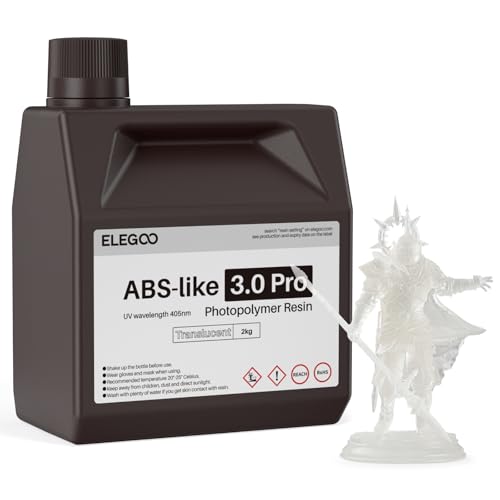
【Higher Scratch-Resistance】 The models printed with ELEGOO Abs-like 3.0 Pro Resin are not easily damaged by the friction and impact of daily use, providing more stable aesthetics.
Processing Parameters: Wavelength, Irradiance, and Dose
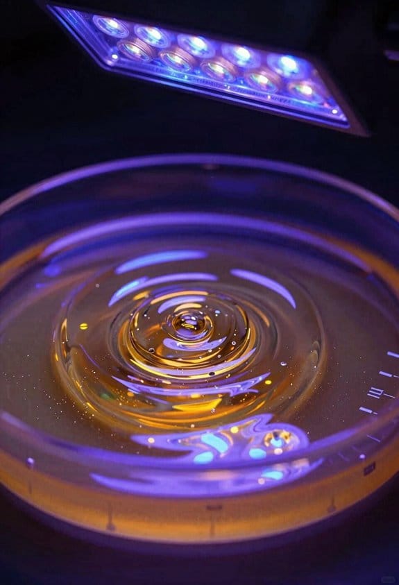
If you’ve ever matched a lamp to a photoinitiator, this is why.
Why it matters: If the lamp spectrum doesn’t overlap the photoinitiator absorbance, you’ll waste photons and get poor cure.
Example: I swapped from a 395 nm LED to a 365 nm LED for a UV-absorbing PI and cut exposure time in half.
1) Check spectral matching
Why it matters: Photons have to be absorbed to start the reaction.
Steps:
- Get the photoinitiator absorbance curve (nm vs. absorbance).
- Get the lamp emission spectrum (nm vs. relative intensity).
- Overlay them and ensure peak overlap within ±10 nm and good intensity across the PI’s main band.
- If overlap is poor, try a different lamp or a different PI with a peak nearer your lamp.
Real-world example: For a TPO-based PI with peak at 380 nm, aligning an LED centered at 385 nm raised initial conversion from 20% to 55% in the first 10 seconds.
I monitor irradiance to control speed.
Why it matters: Irradiance sets how fast the reaction proceeds and how much heat you generate.
Example: A 50 mW/cm² lamp cured a 100 µm film in 12 seconds; a 200 mW/cm² lamp cured it in 4 seconds but made the part reach 60 °C.
2) Control and measure irradiance
Why it matters: Knowing the number tells you whether to shorten time or add cooling.
Steps:
- Calibrate a radiometer or photodiode at the specific wavelength band.
- Measure at the part surface and report mW/cm².
- Adjust lamp distance, lens focus, or duty cycle to target irradiance.
- For sensitive parts, keep irradiance below 150 mW/cm² or add active cooling.
Real-world example: Moving a 365 nm LED from 10 mm to 30 mm from the substrate dropped irradiance from 250 to 90 mW/cm² and prevented blistering on a painted part.
I use dose mapping so energy is uniform.
Why it matters: Dose (J/cm²) — irradiance times time — ensures the whole area gets enough energy.
Example: A flat panel showed edge undercure until we mapped dose and added 2 s extra exposure at the edges.
3) Dose mapping for uniform cure
Why it matters: Uneven exposure creates soft spots and scrap.
Steps:
- Choose your target dose (J/cm²) based on previous cure tests (e.g., 1–3 J/cm² for many acrylates).
- Create a grid across the substrate and measure irradiance at each point.
- Multiply local irradiance by planned exposure time to get local dose.
- Adjust lamp arrangement, add overlapping passes, or change time until every point meets the target dose.
Real-world example: Mapping a 200 × 200 mm part revealed one corner at 60% of target dose; adding a small reflector increased that corner to 102%.
For thick parts, verify cure through the depth.
Why it matters: Surface cure doesn’t guarantee the interior crosslinks enough to get strength and dimensional stability.
Example: A 3 mm printed part looked cured on the surface but was tacky at 1.5 mm depth until we increased dose and switched to a longer wavelength.
4) Depth profiling and adjustments
Why it matters: Depth profiling shows how deep your chemistry actually cures.
Steps:
- Cast test coupons at the same thickness as your part.
- Expose using your planned dose.
- Section or scrape the coupon and measure tack or hardness at different depths (e.g., every 0.5 mm).
- If the middle is undercured, either increase dose by 20–50%, switch to a PI with deeper penetration, or shift to a longer wavelength.
Real-world example: A 2 mm clear coating required adding 0.8 J/cm² to reach adequate hardness at 1.8 mm depth.
Watch temperature and viscosity.
Why it matters: Heat speeds chemistry but can thin or deform parts and change final properties.
Example: Raising temperature from 25 °C to 50 °C halved gel time for one formulation but caused 0.5% shrinkage in part dimensions.
5) Manage thermal effects
Why it matters: Temperature affects reaction rate and final conversion.
Steps:
- Monitor part temperature with a thermocouple or IR gun during exposure.
- Keep peak temperature below your material’s glass transition or deformation point (often <60 °C for many polymers).
- If temperature gets high, reduce irradiance, use pulsed exposure, or add airflow/cooling.
Real-world example: Switching to pulsed LEDs (50% duty cycle) kept peak temperature at 45 °C while preserving the same cumulative dose.
Final practical checklist (do these in order):
- Match spectra within ±10 nm.
- Measure irradiance at the surface (mW/cm²).
- Plan dose = irradiance × time (target J/cm²).
- Map dose across the part and fix low spots.
- Run depth-profile coupons and adjust dose or chemistry.
- Monitor temperature and add cooling if peaks exceed safe limits.
If you follow those steps you’ll avoid most common cure failures.
Recommended Products

[UPGRADED BRIGHT UV LIGHT BEAD]: Made of upgraded powerful UV LED bead, with high power of 10W and 1300mW radiant intensity. The 365nm Light is a real invisible uv light that is not dazzling. It doesn't look as bright as 395nm because it is invisible to human’s eye. But, when it irradiates items containing fluorescent agents, security code or watermark, it will show obvious blue-violet light.
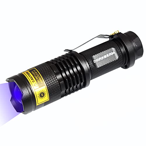
【365NM INVISIBLE LIGHT】--365nm light is invisible to the naked eye, so that it is not as BRIGHT as the 395nm flashlight, but better for detection of high demand like fluorescent agents & security code. Warm tips: Please clear your needs before ordering.

〖Upgraded Powerful UV 365nm Light Flashlight〗The LED UV 365nm light with 10W power output is invisible to the naked eye, so that it is not as BRIGHT as the 395nm flashlight, but more good for detection of high demand like fluorescent agents & security code. And also has USB-C direct charging function, which is good for environmental protection. The portable handheld pet dried urine detector will make your daily life easier!
Limitations: Oxygen Inhibition, Moisture Sensitivity, and Shrinkage
If you’ve ever watched a partly cured UV coating stay tacky on the surface, this is why.
Why it matters: tacky surfaces ruin appearance and block adhesion to the next layer. Oxygen in the air reacts with the radicals that drive UV radical curing and forms peroxy radicals that stop chain growth at the surface. Example: when you spray a UV varnish on a printed poster and leave it in open air, the top 10–50 micrometers can stay soft while the bulk cures. To reduce that surface inhibition, try these steps:
- Purge the cure zone with nitrogen at 2–5 L/min so oxygen falls below ~0.5% and surface cure matches bulk cure.
- Use higher-intensity UV (e.g., 200–400 mW/cm²) for 1–3 seconds to outpace oxygen, or add 0.5–2% amine synergists to your formula.
- Apply a thin tack-free cap coat within 30–120 seconds after the first cure.
A simple shop fix is to drape a clear plastic box over the part during curing; you’ll see the tack disappear.
Think of cationic curing like planting seeds that need an acid to sprout.
Why it matters: water neutralizes those acids and stalls the reaction, so cured parts can have low conversion and poor adhesion. In practice, humidity above ~50% can cut cationic conversion by tens of percent. Example: a cationic primer applied to a cold, damp aluminum door in a poorly ventilated garage may remain undercured and peel. To manage moisture:
- Pre-dry your substrate at 40–60 °C for 10–30 minutes where safe.
- Keep ambient RH below 40% while curing using dehumidifiers or conditioned air.
- Add 0.5–1.5% hydrophobic additives (by weight) or choose less moisture-sensitive photoinitiators.
If you suspect moisture damage, measure surface conversion with FTIR to confirm reduced epoxy ring-opening.
The difference between monomer and network volume comes down to packing.
Why it matters: volume shrinkage creates stress that cracks or delaminates coatings on rigid parts. Typical acrylate systems shrink 2–10% by volume during cure, producing tensile stress of 1–20 MPa depending on layer thickness and substrate stiffness. Example: a 100 µm UV-printed layer on glass can lift at the edges after shrinkage-induced stress concentrates there. To minimize shrinkage stress:
- Use lower-shrinkage monomers (e.g., cycloaliphatic epoxies instead of monofunctional acrylates) or add 10–30% inert fillers like silica beads.
- Reduce film thickness to under 50–100 µm per pass and cure in multiple thin passes.
- Allow partial cure (50–70% conversion) between passes so the network relaxes before final cure.
Measure adhesion with pull-off tests after curing to verify your approach.
A few cross-cutting tips you’ll use right away: check for trapped oxygen in porous substrates by running a 5-second high-intensity test cure and inspecting the surface under 10× magnification; dry-pack or vacuum-bag parts that absorb air; and log RH, lamp intensity, and dwell time for each batch so you can reproduce good runs.
Mitigation Strategies: Nitrogen, Photosensitizers, and Cure Optimization
If you’ve ever had cured resin stay tacky, this is why.
Why it matters: a tacky surface ruins appearance and attracts dust, and it signals low conversion that weakens the part.
1) How does purging with nitrogen help your cure?
Why it matters: oxygen at the surface steals radicals, stopping polymerization.
Steps:
- Set up a simple inert-gas tent or use a small nitrogen nozzle aimed at the surface.
- Purge until you see steady gas flow for 30–60 seconds before irradiating.
- Maintain a light blanket of nitrogen during the first 10–20% of your total exposure, when radical formation is highest.
Example: when I cured a 1 mm thick coating that stayed tacky, running nitrogen at ~1–2 SCFH over the part for 45 seconds removed the surface tack and produced a hard gloss.
Use a low flow so you don’t cool or disturb the resin; too high a flow (over ~5 SCFH) can create bubbles.
2) When should you add a photosensitizer?
Why it matters: photosensitizers let you use available light or cure deeper with the same photoinitiator.
Steps:
- Match the sensitizer absorption to your light source — pick one that absorbs where your lamp emits most (e.g., 400–450 nm for many LEDs).
- Add the sensitizer at 0.1–1.0 wt% relative to the resin, then test with 2–5 second exposures to find the sweet spot.
- Combine sensitizer with the primary photoinitiator at a 1:1 to 1:5 molar ratio, then check for yellowing after cure.
Example: I added 0.5 wt% of a visible-range sensitizer to a formulation and cured a 2 mm part under a 405 nm LED; the center reached non-tacky hardness after 12 seconds instead of 20 seconds.
Be aware: adding too much sensitizer can increase residual color or lower thermal stability.
3) How do you optimize irradiance and dose without over-shrinking parts?
Why it matters: the right light intensity and total dose give you speed without excess shrinkage or heat.
Steps:
- Start with an irradiance that matches your lamp spec — for many LED systems try 10–50 mW/cm² for resins used in coatings and 100–1000 mW/cm² for rapid 3D printing.
- Measure dose (irradiance × exposure time) and increase in 10–20% increments while checking tack and dimensional change.
- Record conversion by degree of tackiness and a simple solvent rub test; stop increasing dose once tack is gone and no visible distortion appears.
Example: for a 0.5 mm film I used 50 mW/cm² and found 2 J/cm² removed tack without warping; doubling irradiance to 100 mW/cm² and halving time caused slight edge curling.
Photoinitiator selection tip: choose blends that absorb where your lamp emits — for example, pair a UV absorber with a visible photoinitiator when using mixed-spectrum lamps. Test small samples first.
A few quick rules you can use right away:
- If surface tack is your only problem, try nitrogen purge for 30–60 seconds first. Works fast.
- If cure is slow through thickness, add 0.2–0.8 wt% photosensitizer matched to your lamp.
- If parts warp when you speed up cure, reduce peak irradiance and increase exposure time to keep total dose similar.
Bold the critical parameter when you log tests, like dose = irradiance × time, so you don’t lose track of what changed.
Recommended Products
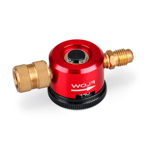
Optimal Nitrogen Flow for HVAC Systems: Designed specifically for HVAC purging and brazing, this nitrogen purge regulator delivers consistent flow at 50 PSI inlet pressure...
Application Guide: When to Use Radical or Cationic Systems
The difference between radical and cationic systems comes down to how they start and keep curing.
Why this matters: choosing the wrong chemistry wastes time and can ruin adhesion or appearance. For example, when printing 4-color process inks on glossy paper at 3000 sheets per hour, cure speed and tack control determine whether the stack sticks together.
Use radical systems when you need very fast cures and you’re working with acrylates or inks. Radicals form within milliseconds under a 300–400 nm UV lamp at 200–300 mW/cm² and build polymer networks quickly. Example: on a UV web press running at 100 m/min, switch to a radical formulation with 1–2% photoinitiator by weight to drop surface tack in seconds. Steps:
- Choose a low-viscosity acrylate oligomer for speed.
- Add 1–2% radical photoinitiator (e.g., DAROCUR 1173).
- Run at 200–300 mW/cm² and measure tack after five sheets.
Use cationic systems for epoxies when oxygen inhibition or low film shrinkage matters. Cationic cures continue after the light source is removed, so you get deeper conversion and better adhesion on difficult substrates. Example: bonding a glass fiber composite panel where shrinkage causes warping — use a cationic epoxy with 1–3% onium salt, cure with a 250–350 nm lamp at 100–200 mW/cm², then let it dark-cure for 10–20 minutes. Steps:
- Select an epoxy oligomer rated for cationic UV cure.
- Add 1–3% onium salt photoinitiator.
- Expose at 100–200 mW/cm² and allow post-cure in the dark for 10–20 minutes.
Consider substrate compatibility and long-term performance before you pick. Some plastics (like PET) tolerate acrylates and peel tests show >10 N/cm adhesion after radical cure, while metals and glass often bond better to epoxies cured cationically. Cationic networks also resist yellowing and stress in high-heat or humid environments, whereas radical networks can be tweaked for higher toughness by adding flexible oligomers or rubber modifiers. Example: for outdoor signage where UV yellowing is a risk, choose a cationic epoxy and measure color change (ΔE) after 500 hours of QUV testing.
Match cure speed, environment, and material:
- Define your priority: speed, adhesion, or stability.
- Pick chemistry: radical for speed; cationic for adhesion and low shrinkage.
- Specify photoinitiator level, lamp wavelength, and power based on substrate and line speed.
If you follow those steps, you’ll pick the chemistry that works reliably for your job.
Recommended Products

💎【Upgrade UV Resin Hard】:The use of higher quality raw materials (polyurethane acrylic resin) makes the UV light curing effect better. After curing, the work is hard and non-stick, and the perfect creation can be presented.

Bonded UV Resin Kit Cured in 5-10 Seconds: LET'S RESIN UV resin for bonding has low viscosity(refer to fluency), strong adhesive, UV curable, odorless&high transparency after curing. Compared with other UV resin, it cures rapidly under the irradiation of a UV flashlight.

[Clear Crystal]: High purity UV epoxy resin, clear and glossy as crystal after curing
Frequently Asked Questions
How Do Photoinitiator Byproducts Affect Long-Term Polymer Stability and Color?
Ironically, I find photoinitiator byproducts often worsen long-term polymer stability and color by leaving residual chromophores that yellow over time and catalyze oxidative degradation, so I avoid them or use stabilizers to mitigate effects.
Can UV Curing Be Fully Monitored In-Line During High-Speed Production?
Yes — I can monitor UV curing inline during high-speed production using real time spectroscopy and inline refractometry together; I’d correlate spectral conversion with refractive index shifts, implement fast data processing, and feedback-control to guarantee consistent cure.
What Safety Measures Are Needed for Workers Handling Uncured UV Resins?
I once burned my thumbnail with sticky resin—so I always insist: I wear personal protective gear (gloves, goggles, aprons), prioritize equipment selection for chemical resistance, and guarantee robust ventilation controls to prevent inhalation and skin exposure.
How Do Additives (Fillers, Pigments) Impact Cure Uniformity and Depth?
Additives reduce cure uniformity and depth: I note particle scattering and pigment aggregation block UV, increase opacity, and create shadowed zones, so I limit loading, use dispersed pigments, and optimize exposure to restore consistent cure.
Are There Standardized Tests Predicting Long-Term Adhesive Durability After UV Cure?
Yes — I use accelerated aging and bond testing protocols (e.g., ASTM, ISO variants) to predict long-term adhesive durability after UV cure, combining thermal, humidity, and mechanical cycling with periodic strength measurements for reliability.