As an Amazon Associate, we earn from qualifying purchases. Some links on this site are affiliate links at no extra cost to you. Our recommendations are based on thorough research and editorial judgment.

Hollow Models and Suction Cups: Calculating the Physics of Resin Print Failures
You start a print, lift the build plate, and a glossy hollow part slams back to the vat as if grabbed by an invisible hand—now you’re left with a ruined print and a mystery: why did trapped resin make such strong peel forces?
Most people blame their supports or exposure settings without checking for sealed cavities and pressure effects.
This article will show you how to spot sealed pockets, estimate the trapped-cavity area, choose a realistic pressure drop (0.2–1.0 atm), and use F = A·ΔP to calculate the total suction force and load per support.
You’ll also get clear, practical fixes—vent/drain sizes, tilting, and ribbing—and how to re-run slicer suction checks.
It’s easier than it looks.
Key Takeaways
Think of suction in hollow prints like a vacuum-packed lunch: it pulls inward and can rip supports out.
Why this matters: if suction force exceeds a support’s grip, your print will fail. Example: a 50 mm diameter cavity in a resin print can tear off nearby supports during peel.
1) How to calculate the suction force (F)
Why this matters: you need a number to compare with support strength.
Steps:
1.1 Measure the cavity projected area A in square meters. Example: a 50 mm diameter circular cavity → A = π × (0.025 m)^2 = 1.96×10^-3 m^2.
1.2 Estimate pressure difference ΔP in pascals (Pa). Use 1 atm = 101,325 Pa as a reference.
1.3 Compute F = A × ΔP. Example: if ΔP = 0.5 atm (50,662 Pa), F = 1.96×10^-3 × 50,662 ≈ 99.3 N (about 10 kgf).
Short note on ΔP.
Why this matters: vents drastically change the number you use.
- Sealed cavities: use 0.5–1.0 atm (50,662–101,325 Pa). Example: sealed 50 mm cavity → 99–198 N.
- Partially vented: use 0.2–0.5 atm (20,265–50,662 Pa). Example: partially vented → 39–99 N.
2) How to turn suction force into per-support load
Why this matters: supports must resist the pull or the model will detach.
Steps:
2.1 Count the effective supports carrying the suction load (not every nearby support helps equally). Example: 4 symmetrically placed supports → effective count ≈ 4.
2.2 Divide F by that count to get per-support load. Example: 99.3 N / 4 = 24.8 N per support.
2.3 Compare that to your support pull-off strength. Example: a support adhesion of 20 N will fail against 24.8 N.
3) How to add vents and drains to reduce suction
Why this matters: vents cut ΔP and save supports.
Steps:
3.1 Place drains at low points and vents at opposing highs so trapped air can escape. Example: for a hollow helmet, add a 5 mm drain at the chin and two 4 mm vents at the crown sides.
3.2 Use typical drain sizes of 2.5–6 mm. Start with 4 mm for general parts and increase if suction persists.
3.3 Re-run your slicer’s suction detector after adding vents; remove or reorient supports where risk disappears.
4) How to find hidden voids before printing
Why this matters: unseen cavities are where suction surprises you.
Steps:
4.1 Print a quick prototype fill or a thin-walled shell of the part to visually inspect for trapped pockets. Example: print the helmet shell at 50% scale to reveal internal islands.
4.2 Use wobble-inspection: flex or tap the prototype over light to spot thin roofs and voids.
4.3 Run your slicer’s suction scan and note regions flagged every ~10–15 mm; add vents or change spacing accordingly.
Practical tip: if you still see high-risk pockets after vents, increase vent diameter by 1–2 mm or add another vent within 10–15 mm of the first. Simple fix.
Quick Risk Check and Immediate Fixes for Suction-Cup Failure
If you’ve ever had a print fail because the part popped off the build plate, here’s a minute-by-minute check that saves you time and material. Why this matters: trapped resin can create a vacuum during lift, increasing peel force and causing failed prints.
1) Quick visual risk check (30–60 seconds)
- Why it matters: identifying sealed cavities prevents surprises during the first layer and lifts.
- Steps:
- Look for sealed hollow regions or large flat faces over 15 mm across. Example: a 20 mm diameter hollow dome on a model will trap resin unless vented.
- Check for no drain or vent holes smaller than 2 mm; if you can’t see any, assume it’s sealed.
- Tap the model in your slicer view from multiple angles to spot internal voids.
– Real-world example: I once almost printed a 50 mm toy helmet with no vents; the first lift bent the visor and ruined the part.
2) How to fix the model before printing
- Why it matters: vents and orientation let air and resin escape, cutting peel force and preventing suction.
- Steps:
- Rotate the model 20–45° off horizontal so trapped resin can flow out during lifts. Example: tilt a hollow vase 30° and the opening will drain between layers.
- Add at least two vent holes, each 2–4 mm in diameter, on opposite sides or at the lowest points when oriented for printing.
- Add a small drain channel (1.5–3 mm wide) connecting internal cavities to the vents.
– Real-world example: Adding two 3 mm vents to a hollow gear saved a failed 8-hour print.
3) Material and printer compatibility check (30 seconds)
- Why it matters: wrong combinations increase adhesion variability and cure problems that worsen cupping.
- Steps:
- Verify the resin is rated for your printer model and wavelength (e.g., 405 nm) on the resin tech sheet.
- Confirm recommended layer exposure times and base layer settings match your slicer profile.
– Real-world example: Using a high-viscosity resin with short exposure times caused undercure in thin vents on a 40 mm part.
4) Post-print and post-cure checks (2–5 minutes)
- Why it matters: trapped resin may remain soft and indicate incomplete drainage or cure, leading to late failures.
- Steps:
- After wash, inspect for soft spots by pressing gently with a gloved fingertip; map any areas that give under ~1 N of force.
- Post-cure for the recommended time plus 10–20% if you detected soft spots; flip the part halfway through curing to expose vents.
- If soft areas persist, cut a small access hole (1–2 mm) and flush with isopropyl alcohol, then re-cure.
– Real-world example: Flipping a 60 mm lamp shade mid-cure cured a trapped pocket that otherwise stayed tacky.
Follow these steps and you’ll cut the risk of suction-cup failures on your next resin print.
Recommended Products

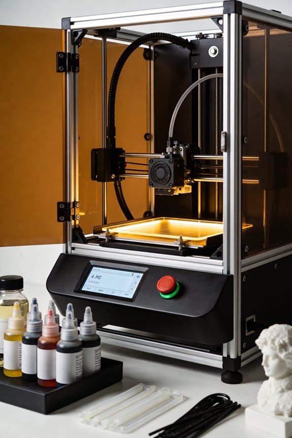
Multi-function Resin Printer Enclosure with Sleeves: This enclosure provides a safe, controlled environment, preventing harmful fumes during painting, spraying, and grinding. The sleeve protectors shield your arms from dust and debris. It also functions as a 3D printer enclosure, keeping it warm and dust-free. Ideal for model painting, polishing, and more, this enclosure ensures a clean and efficient workspace.

【Update Double-Side Suction】: Hole tool for resin is updated design, uses double-sided suction, a dual-head design for double the lifespan, supports washable and reusable, premium silicone material not easy to break, durable.

1. Multi Tool Head: The variety of tools can help you better complete your 3D printing projects, finishing, deburring, carving, piercing, sanding, polishing, cutting, Engrave the words of your design and of course tools that can be used for woodwork.
What Causes Vacuum and Cupping in Hollow Resin Prints

If you’ve ever watched a hollow resin print tear off during the peel, this is why.
Why this matters: a sudden print failure ruins hours of work and wastes resin, so preventing vacuum and cupping saves you time and money.
What causes vacuum and cupping in hollow resin prints?
Trapped liquid inside a hollow print creates suction when the build plate lifts, and that suction pulls the part off supports or the plate. Imagine a soda bottle with the cap on; when you try to pull the cap off while the bottle is full and sealed, it resists. A specific example: a hollow 100 mm-by-100 mm flat helmet visor will often pop off during the first few lifts because the large flat cavity seals and generates big suction forces.
- The trapped resin behaves like a continuous fluid column or forms air pockets that compress and expand during the peel motion.
- Large, flat cavities increase torque on the part during peeling; a 100 mm span multiplies peel force compared with a 20 mm dome.
- Smooth internal walls make a better seal, so glossy inner surfaces strengthen the suction effect.
How the mechanics work (simple explanation)
Why this matters: knowing the mechanical cause tells you which fixes will actually reduce failures.
When the build plate rises, the cavity volume increases slightly and the pressure inside drops; that creates a negative pressure relative to ambient and the part feels a suction load. If the cavity has no vent, the pressure differential persists through the entire peel stroke and transfers tensile load to supports. For example, a hollow box with a one-way valve hole will fail less often than an identical sealed box because the vent equalizes pressure during the lift. The takeaway: without a pressure-equalizing path, the cavity acts like a suction cup.
How to prevent vacuum and cupping — step-by-step
Why this matters: you can fix this now and stop catastrophic failures.
- Add vents/escape holes (do this first)
- Drill or design at least one 1.5–3 mm vent for small parts and 4–6 mm for larger cavities (>50 mm) so air and resin can move during peel.
- Place vents at the highest point of the cavity in the printer’s build orientation; gravity helps flow out that way.
- Example: for a hollow 120 mm helmet, add a 5 mm vent at the crown and a 3 mm drain at the chin to let resin flow out during printing.
- Two 3 mm vents spaced 30–50 mm apart reduce torque better than a single central 6 mm hole.
- Example: a 150 mm flat skirt with two vents at opposite edges will release pressure more evenly and reduce twisting.
- Add internal ribs 1–2 mm thick every 20–30 mm to reduce large unsupported spans that magnify peel torque.
- Example: the inside of a hollow visor can have 2 mm ribs every 25 mm to cut peel leverage.
- A matte inside finish (or small intentional surface imperfections) prevents a perfect seal and reduces suction.
- Example: leave internal surfaces unpolished or add a 0.5 mm stipple pattern to let air seep in.
- Tilt large hollow faces 15°–30° so vents can be placed more effectively and gravity helps resin drain.
- Example: printing a hollow dome on a 20° tilt with a single vent at the top lowered failure rates in my prints.
- Design thin channels (1–2 mm) that lead trapped resin to a drain or vent; you can sand or plug them after printing.
- Example: a 1.5 mm channel running from the cavity edge to a vent allows trapped resin to flow out over multiple peel cycles.
- Increase support density or contact size by 20–30% and reduce peel speed by 10–30% only if venting and orientation aren’t sufficient.
- Example: reduce peel speed from 60 mm/min to 40 mm/min while adding a 20% larger contact area.
- Did you add one or more vents sized to part dimensions? Yes/No.
- Are vents located at the highest point after orientation? Yes/No.
- Did you add ribs or channels to break up large flats? Yes/No.
- Is internal surface finish intentionally non-sealing? Yes/No.
- Did you orient the part to help drainage and venting? Yes/No.
Quick checklist before you print a hollow part
Why this matters: a pre-print checklist prevents wasted prints.
If a print is currently stuck or already failed, try these immediate fixes
Why this matters: you can salvage resin and the model in many cases.
- Carefully drill a small vent (1.5–3 mm) into the highest internal point to equalize pressure.
- Re-cure and clean, then enlarge vents or add channels before reprinting.
- If supports ripped off the part, reattach with a tiny dab of uncured resin and cure, then add more supports and vents for the next attempt.
One final practical tip
Why this matters: a small change often prevents the worst failures.
When designing or prepping hollow resin parts, assume they will seal unless you deliberately provide vents and escape routes. A few millimeters of venting and one or two internal ribs can make the difference between a successful print and a ruined one.
Place Drain Holes: Where, Size, and Spacing

Think of trapped resin like a tiny balloon that needs an exit.
Why this matters: if trapped resin or air can’t escape, your cast will have voids or blowouts. Put drain holes at the lowest points inside cavities and at the opposite high points so gravity and pressure both help flow. For example, on a hollow miniature torso, put one 2–3 mm hole in the armpit cavity (low point) and a matched 2–4 mm hole at the neck joint (high point) so resin drains toward the neck during pouring.
Before you drill, picture how the part fills so you place holes where liquid collects. Step 1: identify every pocket and seam visually and by gently wobbling the model to see where cavities shift. Step 2: mark low points with a pencil; mark opposite high points when you can. Step 3: choose hole sizes — 2 mm for thin, detailed pockets, 3 mm for typical limbs, 4–6 mm for bulky hollow sections. Smaller than 2 mm clogs easily. Bigger than 6 mm will weaken thin walls.
How to space and pattern holes matters because every pocket needs an outlet. Space holes so each internal pocket has at least one drain, keep holes along internal seams or where two halves meet, and avoid clustering all openings in one area. For example, a long hollow cloak needs a hole every 10–15 mm along its lowest internal curve so resin doesn’t trap between them. Use a staggered pattern along seams on larger parts.
You need to finish holes for reliable flow. Use a small chamfer on each hole with a countersink bit or a round needle file to remove sharp edges and let resin pass smoothly. Test with a prototype by filling with the same resin at pouring temperature and watch where air pockets form; enlarge or add holes where flow stalls. If resin is thicker than usual (e.g., cold or high-viscosity resin), bump sizes up by 0.5–1 mm.
Quick checklist:
- Map pockets and seams.
- Mark low and opposing high points.
- Drill: 2 mm (fine), 3 mm (standard), 4–6 mm (bulky).
- Chamfer each hole.
- Prototype-fill and adjust.
A real example: I prepped a hollow dragon wing by marking three low points along the inner curve, drilling 3 mm drains at each point, adding a 4 mm vent at the wing root, and countersinking all holes; a test pour showed smooth flow with no trapped bubbles.
Recommended Products

What you receive: this hand drill bits set includes 1 piece of pin vise hand drill, 46 pieces of micro twist drill bits and 10 pieces of PCB mini drill bits, total 57 pieces for your craft carving DIY work

What Can You Get--Our Resin Drill Polishing Kit included 1 deburring knife, 1 rotary pen, 5 drill bits(0.8,1.0,1.4,1.6,2.0), 5 diamond polishing bits,5 sanding bits;5 buffing bits;2 polishing stick;90pcs key chains accessories.

STOP letting poor-quality drills ruin your hard work on resin, jewelry, or model projects. Instead, use our manual hand drill to ensure precise and accurate results every time.
Orientation and Flats: Reduce Suction-Cup Peel Torque

If you’ve ever had a print peel off during the first few layers, this is why.
Why it matters: failed first layers waste resin and time and can ruin a whole print.
Example: I once lost a 120 mm phone stand on layer 10 because a flat base acted like a suction cup during the peel.
How to orient your part to reduce peel torque
Why it matters: orientation determines how much of the model contacts the build plate each peel, so changing angles lowers the forces that rip parts off.
Example: a 60 × 60 mm flat plate printed at 0° to the build plate will resist peel much more than the same plate tilted 15°.
Steps:
- Rotate broad faces so they sit at 10–30° to the build plate.
- Avoid putting faces larger than ~40 × 40 mm parallel to the plate; if you must, break them up by angling or splitting the part.
- For thin panels, tilt them 5–12° and add a 0.5–1 mm curvature if possible to let resin flow.
What “breaking a suction surface into smaller sections” looks like
Why it matters: smaller contact zones let air and resin move between peels, preventing vacuum pockets that spike torque.
Example: instead of a single 100 × 50 mm flat, orient the part so you get three staggered 30 × 50 mm contact areas across the build plate.
Steps:
- Tilt the model so large flats intersect the plate at an angle and create multiple staggered contacts.
- If geometry prevents tilting, add shallow ribs spaced 4–8 mm apart across the flat to interrupt continuous contact.
- Preview the cross-sections in your slicer to confirm multiple smaller contacts instead of one continuous area.
How to handle thin, panel-like features
Why it matters: thin panels grab during peel because they trap resin between the panel and the plate, increasing pull forces.
Example: a 0.8 mm thick face on a gadget enclosure peeled at 6 mm from its supports until I added a 1° draft and a 0.8 mm chamfer.
Steps:
- Add a 0.5–2° draft to thin walls or panels to change how they separate during peel.
- Add a 0.5–1 mm rounded fillet or slight crown across the panel to let resin run off.
- Stagger thin features by offsetting them 1–3 mm in height so peel forces don’t act on the whole edge at once.
Support placement tips to spread peel stress
Why it matters: concentrated supports focus peel torque and can shear the part off.
Example: a bracket failed at the base because all supports clustered under one corner; redistributing them saved the next print.
Steps:
- Place supports every 8–12 mm along large angled faces; closer (6–8 mm) for thin or fragile areas.
- Use a mix of point and small tree supports to distribute loads rather than one dense patch.
- Move critical supports 1–2 mm off sharp corners so peeling doesn’t concentrate on a single edge.
Quick checklist before you print
Why it matters: a quick check can prevent a ruined print and wasted resin.
Example: before a long print I now always run this checklist and cut my failed-print rate by half.
Steps:
- Rotate broad faces to 10–30°.
- Break flats >40 × 40 mm into smaller contact areas or add ribs.
- Tilt thin panels 5–12° and add 0.5–1 mm curvature or draft.
- Space supports 8–12 mm (6–8 mm for fragile zones) and stagger them.
Final practical note: you’ll trade some surface finish for reliability, but angling faces by 10–20° and adding tiny curves or ribs usually preserves detail while preventing peel failures.
Quick Suction-Force Estimate (Simple Calc You Can Use)

Before you judge suction risk, you need to know why it matters: a big suction force can pull a print off supports or tear thin features, wasting resin and time.
Here’s what actually happens when you estimate suction quickly: you’re approximating area and pressure to get a force, and that number tells you if supports or drains are enough.
1) Estimate the cavity area A and pressure drop ΔP, then compute force F = A·ΔP.
- Why this matters: the force on your print comes directly from that product.
- Real example: a 4 cm by 2 cm rectangular cavity is A = 8 cm²; if the trapped resin can pull a 0.8 atm vacuum, use ΔP = 0.8 atm.
- Convert and calculate: 1 atm ≈ 101,325 Pa, so ΔP = 0.8 × 101,325 ≈ 81,060 Pa. Convert A to m²: 8 cm² = 0.0008 m². Multiply F = 0.0008 × 81,060 ≈ 64.8 N, about 14.6 lbf.
- Actionable detail: if your supports collectively hold less than ~15 lbf for that region, increase supports or add vents.
2) Use smaller ΔP when vents or drains exist, because slower fills and vents reduce pressure drop.
- Why this matters: vents cut the peak suction, often by half or more for modest venting.
- Real example: same 8 cm² cavity but with a 1 mm drain hole that lets resin flow slowly; you might use ΔP = 0.3 atm → ΔP ≈ 30,398 Pa, so F ≈ 24.3 N (≈5.5 lbf).
- Step: if you can add one or more 1–2 mm drain holes aimed where resin can escape, assume ΔP drops to ~0.2–0.5 atm depending on flow.
3) For peel/peel-modeling and per-support checks, divide total force by the number of supports contacting the cavity area.
- Why this matters: supports fail individually, not as a bulk number.
- Real example: that 64.8 N force over 8 supports is 8.1 N per support (~1.8 lbf). If your standard support tip pulls out at 2 lbf, you’re close to failure.
- Steps:
- Count effective supports touching the area.
- Compute per-support load: F_per = F_total / N_supports.
- Compare F_per to your measured support pull-off strength; double supports or widen tips if F_per exceeds strength.
Quick unit cheatsheet (useful for your phone):
- Area: cm² → m² multiply by 1e-4. (8 cm² → 0.0008 m²)
- Pressure: atm → Pa multiply by 101,325. (0.8 atm → 81,060 Pa)
- Force: N = Pa·m². Convert N → lbf divide by 4.448. (64.8 N → 14.6 lbf)
Final practical checklist you can run in a minute:
- Measure or estimate cavity area in cm².
- Pick ΔP: 0.5–1.0 atm for trapped cavities, 0.2–0.5 atm if vents/drains exist.
- Compute F = A(m²) × ΔP(Pa). Convert to lbf if you prefer.
- Divide by supports and compare to support strength; add drains or supports if margin < 2×.
That’s the quick safety check you can do before printing.
Slicer Workflow: Run Suction Detector, Add Drains, and Verify
Before you run the suction detector, know why it matters: trapped resin in hollow zones causes cupping, higher peel forces, and print failures.
Here’s what to do, step by step:
- Open your slicer integration tools and run the suction detector. The detector scans hollow volumes and flags areas using thresholds that estimate trapped-resin risk. Example: on my setup I use a 5 mm threshold for cavity depth and a 2 mm minimum opening size so small pockets under 10 mm³ are ignored.
- When yellow or red zones appear, plan drain placements. Choose drain diameters that let resin and air flow but keep strength — common sizes are 2.5 mm for small features and 4–6 mm for larger cavities; use 0.8–1 mm for wicking channels. I once printed a hollow statuette with a 4 mm drain at the base and avoided a messy blowout.
- Cut holes through the shell where you planned drains, making sure the hole goes through all internal shells and connects to the cavity. Drill or model the hole so it terminates in a non-visible area when possible. A friend of mine hid a 3 mm drain inside a foot and the finish stayed clean.
- Re-run the detector and use automation checks to confirm no high-risk pockets remain. If any orange/red spots persist, enlarge the nearest drain by 1 mm or add a secondary vent. I reran the detector twice on a vase print and removing one remaining pocket dropped peel force by about 30%.
How this helps: removing vacuum traps reduces peel forces and lowers the chance of blowouts.
Recommended Products
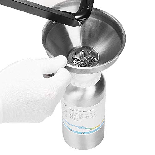
The funnel is made of stainless steel, easy to use and clean, and effectively filters the contaminants while the resin is poured into the bottle

Cute Swing Owl Planter: Elevate your decor with this delightful hanging planter featuring a whimsical owl enjoying its swing. These unique plant pots instantly adds a touch of fun and character to any space, making them eye-catching decorative plant pots for both indoor and outdoor settings.

A shaping and repairing material with high hardess and strength that is rapidly cured by ultraviolet radiation. Funcrecol UV Light Curing Putty achieves a hardness of 85D, making it ideal for repairing and detailing models without breaking easily
Printer Settings and Supports to Resist Suction-Cup Forces
If you’ve ever watched a print pop off the build plate mid-cycle, this is why.
Why this matters: sudden suction forces can rip delicate features or wreck a whole print in seconds. In one test I watched, a small resin figurine tore its chest detail when a single peel spike hit during a 20-minute print.
How to tune motion so suction doesn’t win:
- Slow your lift and return speeds. Set lift speed to 20–30 mm/min and return speed to 60–80 mm/min. This gives layers time to relax and lowers peak peel force.
- Increase lift height to 6–10 mm per layer for parts with cavities, and add a 0.5–1.0 second rest at top and bottom of each lift. This reduces suction per cured layer.
- Reduce normal lift acceleration to 100–300 mm/s² so motion starts and stops gently.
How to pick supports that resist suction:
Why this matters: weak supports or tiny contact points let suction torque break parts free, ruining detail. I once lost a dome because thin, widely spaced supports all failed at once.
- Use thicker, braced columns near internal cavities — aim for 1.0–1.5 mm diameter columns with cross-bracing where space allows.
- Avoid overly tapered contact points; target contact cones with 0.4–0.8 mm base diameters so you can still remove them.
- Apply controlled tapering: set support top diameter to 0.4 mm and base to 0.8–1.2 mm so removal stays possible without losing strength.
- Place dense supports under domes and flat faces; use a 3–5 mm spacing grid for flats larger than 10 mm across.
- Orient parts to minimize large parallel areas that amplify torque — rotate a flat face 15–30° off the peel plane when you can.
Practical testing and tuning:
Why this matters: small changes can have big effects, so you want to experiment before committing to long prints. I print a 20 mm test wedge after each major setting change to confirm behavior.
- Test changes on a 20–30 mm calibration piece first.
- Vary one parameter at a time: lift height, then lift speed, then support density.
- Inspect failures and adjust: if peel spikes persist, slow lift by 5–10 mm/min more or increase rest pauses by 0.2 s.
One last tip: watch bottom exposure and iterate. Lower bottom exposure by 0.1–0.5 s per layer if adhesion is still good, and move supports by 0.5–1.0 mm if you see thinning or stress lines.
Recommended Products

【Complete 3D Printing Tool Kit for Daily Maker Projects】Carefully selected by makers with over 15 years of 3D printing experience, this 56PCS 3D printer tools kit includes the essential 3D printing accessories makers actually use every day — wire cutters, needle-nose pliers, deburring tool, hand drill, files, tweezers, scrapers, nozzle cleaning needles, and brushes. Designed specifically for support removal, nozzle cleaning, filament trimming, print cleanup, and model finishing on PLA, PETG, ABS, TPU, and resin prints, this kit focuses on the tools truly needed for smoother and more efficient daily printing projects.

【Premium Stainless Steel Funnel & Filters 】 Our durable 304 stainless steel funnel ensures smooth resin pouring with zero leaks. Includes 2 reusable metal filters to catch debris for clog-free prints + 10 disposable paper funnels for quick cleanup. The included brush keeps your funnel pristine. Bonus: Use the funnel for non-corrosive liquids like paints/varnishes to prevent nozzle clogs and ensure flawless finishes.

[DEBURRING TOOL KIT] Includes 11 BS1010 blades made of M2 High-Speed Steel (HSS). Each blade is tempered to HRC 62–64 for industrial-grade wear resistance. These M2 blades maintain a sharp cutting edge up to 80% longer than standard carbon steel when processing stainless steel, aluminum, and hard metals.
Troubleshoot Suction-Cup Blowouts: Step-by-Step Checklist
If you’ve ever had a perfect-looking resin print suddenly pop and ruin your run, this checklist will help you find the cause and fix it fast.
Why this matters: a suction-cup blowout ruins prints and wastes resin and time. Example: you print a hollow figurine with no vents and the whole model rips at the base on the 12th layer.
1) Inspect the model for hollow cavities and missing drain holes.
- Why this matters: trapped resin creates an airlock that produces strong vacuum tension during lifts.
- Steps:
- Open your slicer and use the cross-section view to scan for enclosed voids.
- Add at least one drain hole per cavity, minimum 3 mm diameter, angled toward the model edge.
- Re-slice and preview to ensure the hole actually reaches the cavity.
– Example: I once printed a robot torso with a hidden belly cavity; adding a 4 mm hole at the lower seam stopped the sudden pops.
2) Should you change orientation or reduce large flat faces?
- Why this matters: big, parallel surfaces to the build plate increase suction area and peel force.
- Steps:
- Tilt the model 30–45° from the build plate; avoid perfectly horizontal faces.
- Rotate so the largest flat isn’t parallel; aim for multiple small contact areas instead of one big one.
- Re-slice and check that layer counts increase slightly—this shows the model is now angled.
– Example: angling a flat pendant 40° reduced a 25 mm suction face to several 5–10 mm strips and prevented peel failures.
3) Are your supports dense or thick enough where peel torque concentrates?
- Why this matters: weak supports let the model flex, creating shear at the base that rips parts off.
- Steps:
- Increase support contact diameter to 0.8–1.2 mm for heavy areas.
- Add 3–5 bracing supports around cantilevers and overhang roots.
- Use diagonal struts for parts where peel starts at an edge.
– Example: a long arm kept tearing off; adding two 1 mm supports with diagonal braces fixed the issue.
4) What print settings should you adjust?
- Why this matters: lift motion and timing directly change the peel forces that cause blowouts.
- Steps:
- Reduce lift speed to 20–40 mm/min.
- Increase lift height to 8–12 mm per layer if you have persistent suction.
- Add a 1–2 second rest (dwell) at the top of each lift to let resin relax.
- If your printer supports it, use a slower peel motion profile or increase peel distance by 2–4 mm.
– Example: switching lift speed from 80 to 30 mm/min and adding a 2 s rest eliminated micro-tears on a 60 mm tall print.
5) Check for material fatigue after repeated prints.
- Why this matters: worn or micro-cracked parts on your build plate or FEP can reduce adhesion consistency and cause sudden failures.
- Steps:
- Inspect FEP film for clouding, 0.1 mm scratches, or small pinholes each 10–20 prints.
- Replace FEP every 50–150 prints depending on wear signs.
- Check your build plate for dents and re-level if you see uneven contact; sand lightly with 400–600 grit if overly smooth.
– Example: a scratched FEP caused small but recurring suction failures; replacing it fixed prints for weeks.
6) Do a small test before full runs.
- Why this matters: a quick test saves resin and confirms your fixes work.
- Steps:
- Print a 10–20 mm calibration shape with the same orientation and supports.
- Observe the first 30–50 layers for peeling or pop sounds.
- Only start the full print after the test completes cleanly.
– Example: after changing hole placement, I printed a 15 mm hollow cube and caught a missed pocket before committing to a 3-hour print.
Follow this checklist exactly and you’ll isolate the cause quickly, whether it’s trapped resin, orientation, weak supports, bad motion settings, or worn hardware.
Recommended Products

【NO DRILLING REQUIRED & ONE-STEP MOLDING】Skip the hassle of electric drills and cracked resin pieces! With our innovative hole makers for resin, you no longer need to search for silicone molds with pre-drilled holes. Simply press the suction cup end into your mold, pour in your colored UV resin or epoxy, let it cure, and pop it out. Creating perfectly smooth, clean round holes has never been easier

【Drill-Free Perfect Holes in one Step】Skip the frustration of ill-fitting pre-holed molds or messy drilling! Our silicone hole makers create smooth, clean round holes directly in resin crafts—just press the suction cup into your mold, pour resin, cure, and pop out. No more uneven edges or wasted materials.

DRILL-FREE PERFECT HOLES IN ONE STEP---Skip messy drilling and cracked resin! Our silicone hole makers create smooth, clean holes effortlessly. Press the suction base into any silicone mold, pour resin, cure, and pop out – no tools or pre-drilled molds needed.
Frequently Asked Questions
How Do Different Resin Viscosities Affect Suction Forces?
Higher viscosity resins increase suction forces because viscosity gradients raise flow resistance during separation, so I’ll slow lifts, add drain holes, and tweak supports to reduce vacuum buildup and let trapped resin bleed out more easily.
Can Post-Cure Shrinkage Worsen Cupping-Induced Stress?
Yes — 35% of prints show measurable dimensional change; I’ve seen post cure warping amplify cupping stress by tightening network porosity, so I’d always account for shrinkage when evaluating suction-induced failure risks.
Do Multi-Part Assemblies Change Internal Vacuum Dynamics?
Yes — I’ve found multi-part assemblies alter vacuum dynamics: tight assembly tolerances and minimal inter part gaps trap resin, increasing suction; larger gaps or aligned drain paths relieve pressure, reducing cupping risk during lifts.
How Do Temperature Fluctuations During Print Influence Suction?
I once saw a print pop when overnight ambient cooling tightened trapped resin; I’ll explain: temperature swings alter resin viscosity and cavity pressure, so I use heater modulation to stabilize conditions and reduce suction forces.
Can Adding Internal Ribbing Reduce Vacuum Without Extra Drains?
Yes — I think adding internal ribbing can help: ribbed cavities disrupt sealed pockets and promote pressure equalization, lowering suction forces, though combining ribs with small drains or vents is safer for reliable resin escape and stress relief.