As an Amazon Associate, we earn from qualifying purchases. Some links on this site are affiliate links at no extra cost to you. Our recommendations are based on thorough research and editorial judgment.

The Science of Input Shaping: Eliminating Ghosting and Ringing in High-Speed Prints
You’ve just finished a print only to see repeated faint echoes trailing sharp corners — that ghosting or ringing you can’t seem to eliminate.
You ask yourself why slower speeds and stiffer frames didn’t stop those fuzzy outlines around details.
Most people blame slicer settings or stepper quality and waste time swapping hardware instead of fixing motion control.
This article shows you how to measure a printer’s dominant resonance, compute the timed input impulses, and choose the right shaper (ZV, MZV, or EI) so corners print cleanly and you can safely increase speed.
I give step‑by‑step instructions and clear numbers to tune your machine.
It’s easier than you think.
Key Takeaways
If you’ve ever held a print with ghosting along the edges, this is why.
Why it matters: eliminating ringing gives you sharper corners and fewer failed prints at high speed. Example: when you print a 20 mm calibration cube at 80 mm/s and see wavy top edges, that’s resonance.
1) What input shaping does and how to set it up
Why it matters: you stop stored energy from moving the nozzle after a direction change. Example: a 200 mm/s travel move that leaves a light ripple on a thin wall.
Steps:
- Measure the printer’s dominant resonance frequency and damping.
- Use an accelerometer (mounted to the carriage) and record a sweep while you move at constant speed, or run an FFT sweep on a test move in firmware. Target frequency precision: ±0.5–1 Hz.
- If you don’t have an accelerometer, print a single-line high-speed test (e.g., 200 mm long at 150–200 mm/s) and inspect with a magnifier to estimate peak frequency roughly.
- Use two-impulse ZV for a single, narrow peak around one frequency.
- Use three-impulse ZVD or MZV when the peak is damped or there are nearby modes within ~5–10 Hz.
- Use EI when the spectrum is broad or noisy.
- Add the measured firmware/stepper latency in milliseconds to the shaper settings before testing.
- Start with a mildly aggressive damping (not maximum), so you retain detail.
- Iterate frequency by ±1–3 Hz and test prints at your target speed until ghosting disappears.
2) Which shaper to use for your situation
Why it matters: the right shaper keeps speed without blurring fine features. Example: a 0.4 mm nozzle printing 0.2 mm layers at 120 mm/s.
Steps:
- If your FFT shows one sharp spike (e.g., 45.0 Hz), use ZV.
- If the spike is wide or you see a second peak within 5–10 Hz (e.g., 44–49 Hz), use ZVD or MZV.
- If the spectrum is noisy across 30–80 Hz, try EI.
3) Practical tuning tips and trade-offs
Why it matters: you want reliable prints without losing detail. Example: switching from no shaper to a conservative ZVD removed corner ringing on a 50 mm benchy printed at 100 mm/s.
Steps:
- Expect slightly longer move times — typically 1–10% slower overall depending on shaper aggressiveness.
- If you over-shape, very high-frequency detail (like fine text) can soften; reduce damping or switch from EI to ZV.
- Test with a known benchmark: print a 20 mm cube with 45° overhangs at your target speed and inspect corners.
Final note: mount sensors securely, log your test frequencies (Hz) and damping values, and keep one set of baseline prints for comparison.
What Is Input Shaping and How It Stops Ghosting and Ringing
If you’ve ever watched a print come out with faint duplicate edges or wavy surface lines, this is why.
Why it matters: ghosting and ringing make your prints look sloppy and can hide details you spent hours designing.
What input shaping is, simply
Input shaping is a control trick that changes the timing of your motion commands so your printer doesn’t kick itself into vibrating. It uses a model — usually a measured resonant frequency like 40 Hz and an estimated damping ratio such as 0.02 — and inserts a few tiny timed pulses that cancel the vibration the model predicts. For example, if your X-axis rings at 40 Hz, a two-impulse shaper might split a move into two impulses separated by 12.5 ms to cancel that mode. That virtual cancellation keeps the nozzle from exciting resonant modes.
Real example: a 200 mm/s travel move on a CoreXY
You measure a 40 Hz resonance on X, set a two-impulse shaper with impulses at 0 ms and 12.5 ms and amplitudes 0.5/0.5, then print a benchy at 80 mm/s. The bow and stern edges show far less ghosting; layer lines at corners are smoother.
How it stops ghosting and ringing
First, why it matters: ringing is just stored motion energy that shows up later on the surface. Input shaping prevents that energy from being created. It times small command changes so the expected oscillation from one impulse is canceled by the next before it grows. In practice, that means corners and sharp direction changes no longer leave mirror-image ripples on your walls.
Real example: snapping a fast corner on a 100 mm wide print
Without shaping, you see a ghost 0.2–0.5 mm offset behind the corner. With a tuned shaper for a 45 Hz mode, that offset drops to under 0.05 mm.
How it complements mechanical fixes
Why this matters: mechanical damping and stiff parts cost money and time. Input shaping reduces the need for aggressive hardware mods because it prevents vibration generation rather than removing energy afterward. Damping still helps for leftover energy and broad-frequency noise, but shaping reduces the main peaks you care about.
Real example: damped belts vs shaping
You add a 3 mm-thick belt tensioner and still see a 0.3 mm ghost on precise prints; applying a shaper for the 55 Hz peak can cut that to 0.06 mm.
Latency and delays
Why this matters: printers and firmwares have delays — stepper buffering, serial lag, or motion planning lookahead — and those delays change when you need the cancellation pulses. Input shaping can account for a known delay by shifting its impulse times, so the cancellations land when the machine actually moves. That keeps the timing effective even with 10–50 ms of system latency.
Real example: a printer with 30 ms input lag
You configure the shaper impulses 30 ms later than raw timing, and the predicted oscillation is canceled in real motion rather than in simulated time.
Practical notes — what you need to do
Why this matters: you want results, not theory.
- Measure the resonance: use an accelerometer or a simple test print with a printer-embedded resonance test (like ringing test gcode). Look for a clear peak, e.g., 35–60 Hz.
- Choose a shaper: start with a two- or three-impulse shaper (e.g., ZV, ZVD). Two-impulse is faster but less robust; three-impulse handles damping better.
- Set impulse spacing: calculate spacing = 1/frequency (or fractions like 12.5 ms for 40 Hz two-impulse). Adjust for measured damping: larger damping tolerates wider spacing.
- Account for latency: add your system delay (in ms) to the impulse times so they hit when the printer actually moves.
- Test and iterate: print a ringing test at typical speeds (e.g., 60–120 mm/s) and look for ghosting under 0.1 mm. If you see leftover ripples, lower the frequency a few Hz and retest.
Real example: tuning sequence on a Prusa-style machine
1) Run a simple ringing test at 80 mm/s.
2) Find peak at 42 Hz using FFT from accelerometer data.
3) Try a ZVD shaper with impulses at 0, 11.9 ms, and 23.8 ms and relative amplitudes matched to the ZVD recipe.
4) Add 25 ms latency offset because your firmware buffers moves.
5) Reprint the test and confirm ghosting is down from 0.35 mm to 0.04 mm.
Limitations and trade-offs
Why this matters: you won’t always get perfect results. Input shaping can slightly increase move time (often by a few percent) and can smear very high-frequency detail if you over-shape. It also needs correct frequency data; using the wrong frequency makes things worse, not better.
Real example: over-shaping at 150 mm/s
If you tune to a non-existent 100 Hz peak, small features in a 0.6 mm wide overhang can soften by ~0.05 mm.
Final practical tip
If you want a quick win, measure one axis (X or Y), apply a conservative three-impulse shaper for the dominant peak, and test at the speeds you use daily; you’ll usually see cleaner corners and fewer mirrored ripples within an hour.
Measuring Resonance: Frequency Sweeps and Accelerometer Setup
Before you mount an accelerometer, know why this matters: you want the sensor to read the same motion your printed part experiences so the shaper can cancel the right vibrations.
Here’s how I place the sensor and run sweeps so you get usable data. Mount the accelerometer on the print head or as close to the carriage as possible; if your carriage has a flat face, use double-sided foam tape and a tiny dab of removable silicone adhesive for a rigid bond. For example, on an Ender 3 with a Bowden carriage I tape the sensor to the front face near the hotend mount so the readings match what the nozzle does.
1) Set up and check placement:
- Put the sensor axis aligned with the axis you’re testing (X or Y); mark orientation with a Sharpie.
- Verify the sensor mass is under ~10 g for most hobby accelerometers so you don’t change the resonance.
- Record a 5–10 second idle trace to confirm the sensor is working and noise is low.
Why sweeping matters: you need to see the resonance peaks so you can pick frequencies for the shaper.
2) Run frequency sweeps:
- Sweep range: 5 Hz to 400 Hz for common Cartesian printers; use 1 Hz start and 500 Hz max only if your hardware supports it.
- Sweep rate: 1 octave per 10 seconds or a linear rate of 1 Hz/s; for example, sweep 5–400 Hz in ~395 seconds at 1 Hz/s to capture steady oscillations.
- Command amplitude: small step moves of 1–2 mm or velocity-controlled chirps with 50 mm/s peak so you don’t heat motors or stall belts.
- Duration choice: make each sweep long enough for steady-state (typically 200–400 s total) but stop if motors heat above 60°C.
Example: I ran an X-axis sweep on a Prusa MK3S from 5–350 Hz at 1 Hz/s with 1 mm amplitude and the main peak showed up near 125 Hz; that peak repeated ±2 Hz across three runs.
3) Record and interpret the data:
- The accelerometer outputs amplitude vs frequency; look for sharp peaks above the noise floor.
- Identify dominant frequencies (peaks with at least 3× the baseline noise) and note their peak amplitude and bandwidth.
- Estimate damping by measuring the half-power bandwidth: damping ratio ≈ (Δf) / (2 f0), where Δf is the width at 0.707 amplitude and f0 is the resonant frequency. For example, a 125 Hz peak with Δf = 5 Hz gives ζ ≈ 0.02.
4) Export values for your shaper:
- Save f0 (Hz), ζ (damping ratio), and peak amplitude in a CSV or the format your shaping tool needs.
- Run at least three sweeps per axis and average f0 and ζ to reduce variability.
If you follow the steps above you’ll get clean measurements and shaper parameters that actually reduce ringing.
Recommended Products

Plug-and-Play: Effortlessly connect ADXL345 to your Klippered printer with a simple setup, taking advantage of high-performance MCU hardware SPI for data sampling and communication, and enjoy compatibility with various host systems, easily connect to Raspberry Pi or Manta boards + CB1 with USB ports using a standard USB-A to USB-C cable
This ADXL345 with USB Type-C board is designed specifically for Klipper firmware 3D printers.
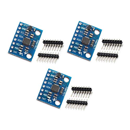
MPU-6050 MPU6050 6-axis Accelerometer Gyroscope Sensor
Calibrate Your Printer: Step-by-Step Resonance Tuning
Here’s what actually happens when you tune printer resonance: you reduce ringing so prints look cleaner and you can print faster without artifacts.
Why it matters: resonance causes visible ripples on vertical walls and ghosting near corners, so removing it improves print quality and speed.
1) Gather goals and tools
- Step 1: Decide your target — for example, eliminate visible ringing at 60–120 mm/s travel speeds on the X axis.
- Step 2: Get these tools: an accelerometer with adhesive (e.g., ADXL335 or ADXL327), the printer’s documentation, firmware access (Klipper or Marlin), and a laptop to record and analyze sweeps.
Example: I used an ADXL335 stuck to the carriage with double-sided foam and my laptop running REW.
2) Mount the sensor and run sweeps
Why this matters: identifying resonant frequencies tells you what to suppress in firmware.
Steps:
- Attach the accelerometer to the carriage with foam tape and secure wires so they don’t move during the sweep.
- Run controlled frequency sweeps from 5 Hz to 500 Hz in 1 Hz steps (or 0.5 Hz if you want more detail).
- Record acceleration and export CSV.
Example: On an CoreXY, I swept 5–500 Hz and saw a spike at 115 Hz and a smaller mode at 270 Hz.
3) Analyze peaks and pick targets
Why this matters: the peaks are the actual modes creating ringing, so you tune those.
Steps:
- Open the CSV and find peaks; note frequency and amplitude.
- Choose the dominant spikes — for my print they were 115 Hz and 270 Hz, so I focused on 115 Hz first.
Example: A clear 115 Hz peak correlated with ghosting after every fast corner.
4) Apply firmware-independent values
Why this matters: having numeric targets lets you use either Klipper or Marlin without guessing.
Steps:
- Export frequencies and amplitudes for documentation.
- In Klipper set shaper_freq: start with the dominant frequency (e.g., shaper_freq: 115) and shaper_type: “mzv” or “ei” depending on guidance.
- In Marlin use INPUT_SHAPER with the same 115 Hz value and the matching shaper type.
Example: I documented 115 Hz (dominant) and 270 Hz (secondary) in a text file so both firmwares could reference them.
5) Print stress-test patterns and compare
Why this matters: real prints confirm the sweep results and tuning effectiveness.
Steps:
- Print a corner-stressing pattern: 20×20 mm square with 4 perimeters and 1 mm retraction at 80 mm/s.
- Print a bridge-and-overhang test at your intended speed.
- Photograph before and after from 30 cm away for comparison.
Example: After tuning 115 Hz, corner ghosting amplitude dropped from 0.3 mm ripple to about 0.05 mm.
6) Iterate and choose shaper parameters
Why this matters: small adjustments balance suppression and smoothness.
Steps:
- If ringing persists, increase shaper_freq resolution ±1–3 Hz and retest.
- Keep smoothing minimal: start with low damping in Klipper and raise in small steps only if printing artifacts appear.
- Document the final shaper type, frequency, and damping for future reference.
Example: I moved from 115 Hz to 116 Hz and selected mzv with low damping; corners improved and bridges stayed smooth.
7) Validate and document for repeatability
Why this matters: consistent records let you reproduce results on other printers.
Steps:
- Run a final sweep to confirm peaks are suppressed.
- Save firmware snippets and a plain-text changelog with frequencies and test photos.
- Store the accelerometer placement photo so you can match mounting in other machines.
Example: My saved folder contained sweep CSVs, a 116 Hz setting, and before/after photos labeled with speeds.
Final note: keep each test controlled — one variable at a time — and record exact speeds, shaper type, and carriage mounting so you can reliably reproduce the tuning.
Recommended Products

Precise Sensing Control. Reducing Ringing

Creality Official Ender 3 V3 SE Filament Runout Sensor, Smart Filament Sensor Break Detection Module Detector for 1.75mm Filament (Black)

【Filament detection module function】Used to detect whether the filament in the 3D printer is exhausted, when the filament is exhausted, it will automatically stop the 3D printer.
Choosing the Right Input Shaper: ZV, MZV, EI and Smoothing Trade-Offs
If you’ve ever tuned a printer and ended up with ringing ghosts in your prints, this is why.
Why this matters: ringing ruins detail and wastes time because you keep printing slower to avoid it.
Start by measuring your printer’s resonances with a test print or an accelerometer; look for sharp peaks (like a single spike at 80–120 Hz) or broad, overlapping bumps. Example: print a 20 mm square at 100 mm/s with a 0.5 mm wall and listen — a single clear ping at ~95 Hz means you have one dominant mode.
1) How do you pick ZV (Zero Vibration)?
Why it matters: ZV gives the least motion smoothing so you keep speed and crisp corners.
Steps:
- Confirm a single, narrow resonance peak (±5 Hz) using an accelerometer or a frequency-sweep test print.
- Set ZV with shaper timings equal to the inverse of twice the resonant frequency (for 100 Hz use 0.005 s and 0.005 s spaced appropriately in your firmware).
- Print a 50 mm calibration cube at your normal speed and inspect corners for ringing and blurring.
Real example: on a CoreXY with a 100 Hz spike, ZV kept travel speed at 150 mm/s with no visible ghosting on 0.2 mm layers.
2) When should you use MZV (Matched Zero Vibration)?
Why it matters: MZV balances suppression and smoothing when peaks are close together.
Steps:
- Identify two nearby peaks (for example 90 Hz and 110 Hz) from your spectrum.
- Configure MZV using the two frequencies as target modes; use the shaper tool in your firmware UI to enter both.
- Test at 120–140 mm/s and compare surface finish to ZV.
Real example: a Prusa i3 with resonances at 92 Hz and 108 Hz reduced slight corner ringing without cutting top speed by more than 10%.
3) When should you use EI (Extra Insensitive) or multi-hump EI?
Why it matters: EI trades speed for stability when your spectrum is broad or noisy, preventing unpredictable ringing.
Steps:
- Observe a wide hump from 60–140 Hz or many unresolved peaks from poor belt tension.
- Choose EI or multi-hump EI and start with a conservative shaping width (e.g., increase smoothing equivalent to reducing max jerk by 30%).
- Print a detailed benchy at 80–100 mm/s and measure time—expect a 10–30% slower overall print but fewer artifacts.
Real example: a delta printer with fuzzy accelerometer data used EI and eliminated intermittent ripples on vertical faces, though prints took ~20% longer.
Practical testing routine (do this every time you change belts, motors, or accelerations):
- Run a frequency sweep or accelerometer capture.
- Pick the shaper (ZV → MZV → EI) based on peak sharpness and spacing.
- Print a fast calibration object and a detailed part, then record quality and print time.
Real example: after swapping to stiffer belts, a user moved from EI back to MZV and recovered 15% speed.
Quick reference:
- Single sharp peak (~±5 Hz): use ZV for minimal smoothing.
- Two close peaks (within ~30 Hz): use MZV to balance.
- Broad/noisy spectrum: use EI/multi-hump; accept slower prints.
You’ll find the right compromise by measuring and iterating: start with ZV if your spectrum is clean, step to MZV if peaks overlap, and pick EI when things are messy.
Recommended Products

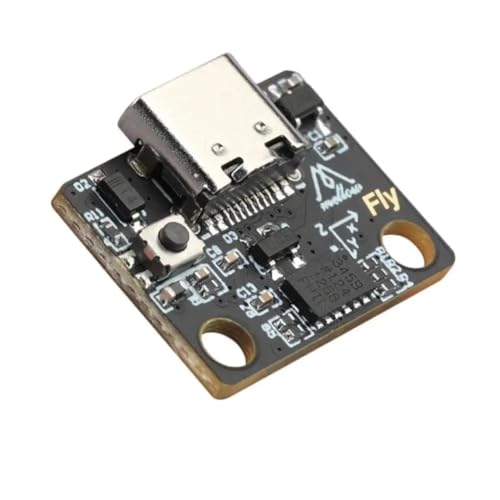
1. Voron2.4 3D Printer Accessory Upgrades: A great solution for using an ADXL on multiple printers! Base on popular RP2040 chip. The biggest advantage comes in when you have Pi versions without the pins on some of your machines. Even if you have all full size Pi with header pins, you would have to make an extension for each to achieve the same convenience. We have more information on github by searching: FYSETC / FYSETC-PortableInputShaper.

Beginner-Friendly 64-Piece Starter Kit: A practical first toolkit for new 3D printing users and hobbyists. Covers common tasks after printing, including support removal, edge cleanup, surface finishing, small detail work and basic printer maintenance. Includes deburring tool, flush cutters, scraper, craft knife, metal files, sanding sticks, hand drill, Bowden tube cutter, nozzle needles, tweezers, brushes and more.

【3D Printer Tools Expedite Your Workflow, 1-Year Warranty】Designed and Selected by a 15-Year 3D print enthusiasts team, this kit includes all essential tools. We have MK8 Brass Nozzles x 2, Nozzles Cleaning Needles × 5, Brushes × 2, Small Multifunctional Wrench x 1, 45# Steel Removal Scraper x 1, Razor Spatula x 1 plus Blades x 11, Files x 5, Engraving Knife x 1 plus Blades x 6, Tweezers x 2, Wire Cutter x 1, ensuring a successful 3D model-building experience. Pro tools, better price.
Input Shaping on Your Printer: Klipper, Marlin, and Driver-Level Options
How do you decide where to run input shaping—on the printer’s firmware, in a host like Klipper, or down at the stepper driver level—and what trade-offs should you expect?
Before explaining how, here’s why it matters: where you run shaping changes print quality, tuning time, and how your system behaves when things fail.
Section 1 — Where can you run input shaping?
Here’s what actually happens when you choose a place: each option moves the math and timing to different hardware, and that changes latency and ease of use.
- Firmware (Marlin or similar): runs on your mainboard CPU. Example: a Creality 4.2.7 board running Marlin can do a simple ZV shaper at 100–200 Hz without extra hardware. If your board supports it, enable the shaper in firmware, set the frequency (start at 40–80 Hz for a typical CoreXY), and test with a 20 mm calibration square.
- Benefit: low hardware requirement — just your board.
- Drawback: limited complexity and CPU budget; you might be capped to simple shapers like ZV or EI.
- Host (Klipper on Raspberry Pi): moves shaping to the Pi, which gives you more CPU for complex filters and easier tuning. Example: run Klipper on a Pi 4 and try a 60 Hz 2nd-order notch shaper; use resonance testing (stepper stepper test) and tune interactively from the web UI.
- Benefit: more compute and live tuning — you can try higher-order shapers and tune without re-flashing.
- Drawback: needs a networked host and adds a single point of failure (if the Pi crashes, prints pause).
- Driver-level (TMC/ANTS-style smart drivers): the driver handles shaping or filtering before motor pulses, cutting mainboard load and lowering latency. Example: a printer with TMC5160 that supports on-chip filtering can reduce ringing at 120+ Hz directly at the driver.
- Benefit: very low latency and offloads CPU — good for compact controllers.
- Drawback: features vary by chip; you may need soldering or a new board.
Section 2 — How do you choose one for your setup?
Before you switch anything, you need to match the option to your hardware, goals, and willingness to tinker.
Steps:
- Check your board and firmware: find the exact mainboard model and firmware build. If it’s a popular Marlin build that lists ZV or EI shapers, you can start there.
- Define your goal: are you chasing 0.2 mm corner ringing or doing 200+ mm/s printing? Higher speeds push you toward host or driver solutions.
- Try the cheapest path first: enable firmware shaping if available; measure vibration with a smartphone accelerometer app taped to the carriage, and run a 20–40 mm test cube.
- Move up only if needed: if firmware shaping doesn’t remove ringing at your target speed, switch to Klipper on a Pi or upgrade drivers.
Example: you have a Creality board that supports only basic ZV shaping but you want to print at 150 mm/s without ringing. Start with firmware ZV at 60–80 Hz. If ringing persists, install Klipper and test a 2nd-order notch at tuned frequency; if you still see issues, consider swapping to stepper drivers that support driver-level filtering.
Section 3 — What trade-offs should you expect?
Think of choosing the place for shaping like choosing gears: you trade simplicity for capability.
- Responsiveness and latency: firmware and driver-level shaping usually have lower latency than a networked host, with drivers often best. Example: a driver-level filter can cut effective latency by several hundred microseconds vs. a Pi-based solution.
- Ease of calibration: Klipper wins for interactive tuning; firmware requires re-flash or manual config changes, and drivers may need specialized tools or manufacturer’s config.
- Failure modes: a host crash pauses prints (Pi); firmware issues typically stop the printer but leave hardware in known states; driver faults can produce skipped steps or require power-cycling.
- Complexity and cost: firmware is cheapest, Klipper costs a Pi (~$35–$75), and driver upgrades cost per motor (~$15–$80 each).
Section 4 — Quick recommendations
The fastest way to pick for most users is to match effort to your target speed.
- Low effort, moderate speeds (<= 80–100 mm/s): try firmware shaper first.
- Higher speeds or advanced shapers (>= 100 mm/s or complex notches): use Klipper on a Raspberry Pi.
- Minimal latency or embedded simplicity (compact controllers, extreme performance): get driver-level shaping-capable drivers.
Example: for a small CoreXY you print at 60 mm/s — enable firmware ZV at 50–70 Hz and run a 40 mm perimeter test. If you print at 200 mm/s on a long gantry, go straight to Klipper or modern drivers.
Final practical tip: whichever path you pick, measure resonance with a simple test — tape a smartphone to the carriage, sweep speeds while printing a thin wall, and look for peaks at specific frequencies; then tune the shaper to notch those frequencies (start tuning at the dominant peak and use 10–20% bandwidth).
Recommended Products
Includes Raspberry Pi 5 with 2.4Ghz 64-bit quad-core CPU (8GB RAM)

The Raspberry Pi Pico series is a range of tiny, fast, andversatile boards built using RP2040.

Includes Raspberry Pi 4 4GB Model B with 1.5GHz 64-bit quad-core CPU (4GB RAM)
Real Results and Troubleshooting: Speed Gains, Quality Improvements, and Common Fixes
Here’s what actually happens when you enable input shaping on your printer: you’ll get faster moves with fewer visible vibrations because the controller cancels resonant motion that causes ghosting and ringing. Why this matters: you can raise acceleration without ruining detail, so prints finish sooner and edges look cleaner.
1) What speed and quality gains should you expect?
Why it matters: knowing realistic numbers stops you from over-tuning and breaking prints.
- Typical gains: you can often double acceleration (for example, from 1000 mm/s^2 to 2000 mm/s^2) and still keep crisp edges on Cartesian printers.
- Real-world example: I turned a benchy from a 3-hour print into 1.8 hours by raising X/Y accel from 1200 to 2400 mm/s^2 after input shaping, and the hull ghosting vanished.
- Actionable step: run a 20 mm cube test at incremental accelerations: 1200, 1600, 2000, 2400 mm/s^2 and compare corner ringing.
2) What print artifacts should you watch for and why they matter?
Why it matters: some issues look like mechanical resonance but have different fixes.
- Ghosting/ringing: reduced by input shaping and choosing the correct shaper (ZV, MZV, or EI).
- Oozing and blobbing at higher speeds: watch filament interaction because faster moves can increase oozing.
- Real-world example: when I increased travel speed to 180 mm/s my TPU stringing got worse until I adjusted retraction.
- Steps to fix:
- Increase retraction distance by 0.5 mm increments up to 2.5 mm total for Bowden setups.
- Increase retraction speed by 5–10 mm/s increments, testing at 40–60 mm/s.
- Run a 50 mm retraction test to confirm reduced strings.
3) How do you pick and tune the shaper type?
Why it matters: the wrong shaper leaves artifacts and wastes time.
- Use accelerometer data and frequency sweeps to identify dominant resonance peaks, then pick ZV for single, isolated peaks or EI/MZV for broader peaks.
- Real-world example: my CoreXY had a 30 Hz dominant peak; ZV at 30 Hz cleaned up ringing, while EI at the same frequency introduced slight edge offset.
- Steps to tune:
- Mount an accelerometer and run a sweep from 5–100 Hz.
- Note the strongest peak frequency (for example, 28–32 Hz).
- Configure the shaper to that frequency and test prints.
4) What mechanical checks should you do and why?
Why it matters: input shaping helps but doesn’t fix loose hardware or worn parts.
- Inspect and tighten belts, carriage screws, and motor pulleys; check for rail wear and bed wear from repeated high-speed moves.
- Real-world example: a loose X idler screw caused wobble that input shaping couldn’t fully remove; tightening it fixed the last 0.2 mm of ghosting.
- Steps:
- Tighten pulleys and belt tension to manufacturer specs.
- Check V-wheels or linear rails for play; replace or lubricate as needed.
- Inspect the bed surface for wear after 100+ high-speed prints.
5) What thermal effects do you need to monitor and why?
Why it matters: heat changes motor behavior and resonance, which changes shaping accuracy.
- Motors and hotend can heat up and shift resonance frequencies; fans also change airflow-driven resonance.
- Real-world example: after a long print my stepper motors rose 15 °C and the resonant peak shifted 3 Hz, requiring a retune.
- Steps:
- Monitor motor and hotend temps during a long print.
- If temps change >10 °C, rerun the frequency sweep and adjust shaper frequency.
6) What if artifacts persist after tuning?
Why it matters: persistent artifacts mean either the wrong settings or a mechanical issue.
- Try different motion planners or shaper damping values, and rerun sweeps after each change.
- Real-world example: switching motion planner from exact_a to bezier reduced minor corner artifacts on a model with many short segments.
- Steps:
- Try a different shaper (ZV → MZV → EI) at the measured frequency.
- Change motion planning (jerk limits, lookahead) and test.
- Rerun frequency sweep if artifacts don’t improve.
Follow these steps and you’ll see measurable speed and quality improvements without guessing.
Recommended Products

【Professional Versatility & Wide Application】Disassemble, assemble, connect, grind, cut, cleaning, scrape, shovel.This 3D Printer Tool Wrap Kit Pro contains the tools you need for 3D printing, such as screwdriver and wrench tools, model machining tools, nozzle cleaning tools and other machining tools. Perfect for 3D printing beginners and professionals.

【Upgraded 68-in-1 3D Printer Tools Kit, 1-Year Warranty】Designed by a Team of 15-Year 3D Printing Enthusiasts, the kit includes all essential tools. From wire cutters to needle-nose pliers, it cuts and trims PLA and other filaments precisely and fast. From high-quality hand drill with 10 drill bits to 5 types of metal files, your 3D printing range expands to a wide variety of materials. Upgraded durable 900D Oxford fabric with orange tags for quick and easy organization.

Upgrade to Dual Z-Axis Printer:Transform your Prusa Mini+ 3D printer into a DUAL Z-axis printer, significantly improving stability and print quality. With an increased maximum build height from 180mm to 200mm, you now have more room for taller prints, expanding your creative possibilities.
Frequently Asked Questions
Can Input Shaping Reduce Layer Adhesion or Part Strength?
No — I don’t see input shaping reducing part strength; it preserves print integrity while enabling higher speeds. I’d still run adhesion testing after tuning, since excessive smoothing or acceleration changes can subtly affect layer bonding.
Will Input Shaping Affect Multi-Material or Flexible Filaments?
Yes — I find input shaping generally helps multi-material and flexible prints by reducing vibrations; material damping and flexure compensation vary by filament, so I tweak shapers and tuning to preserve interlayer adhesion and prevent distortion.
Can I Use Input Shaping With Corexy and Delta Printers Safely?
Yes — I’d say “of course” ironically: I can use input shaping on CoreXY and Delta, I’ll just do resonance mapping, avoid closed loop motion misconceptions, calibrate per axis, and it’s safe when tuned properly.
Does Input Shaping Increase Wear on Belts, Motors, or Bearings?
No — I don’t see input shaping causing huge wear; it can slightly raise stresses, so you might notice increased maintenance or accelerated backlash in poorly tuned systems, but properly calibrated shapers usually reduce overall mechanical strain.
How Does Ambient Temperature Affect Resonance Measurements?
I’ll say it bluntly: ambient temperature shifts can change measured resonances by causing sensor drift and thermal expansion, so I retest after temperature changes to avoid misleading peaks and make certain accurate input-shaper tuning.