As an Amazon Associate, we earn from qualifying purchases. Some links on this site are affiliate links at no extra cost to you. Our recommendations are based on thorough research and editorial judgment.
Non-Planar 3D Printing: Moving Beyond Traditional Z-Axis Slicing
You’ve watched a curved 3D print come off the bed and wondered why the smooth curve still shows stair‑steps and weak seams along the Z layers.
You’ve asked whether the nozzle can simply follow the part’s contour instead of stacking flat slices and whether that would actually strengthen the print.
Most people assume slicing must always produce flat Z layers and try to hide steps with post‑processing or cosmetic tricks.
This article shows you how to generate coordinated X‑Y‑Z toolpaths so the nozzle traces contours, what firmware and slicer features must support true 3D motion, and the hardware, tuning, and collision checks required to print stronger, smoother curved surfaces.
You’ll get a practical workflow and clear limits to test on your machine.
It’s easier than it looks.
Key Takeaways
If you’ve ever tried printing a curved part and saw layer lines ruin the look, this fixes that. Non‑planar printing matters because it reduces visible stair‑stepping on curved surfaces by moving the nozzle in X–Y–Z at the same time; for example, printing a mug with the nozzle following the rim contour cuts stepped rings so the rim looks smooth.
Why aligning rasters with stress matters: when you print along the load path, parts get stronger. For a cantilevered bracket, orienting perimeters and rasters to follow the bending direction can roughly double fatigue life compared with standard layer stacking.
There are two practical ways slicers implement non‑planar paths. Native 3D toolpaths calculated by the slicer keep the nozzle oriented away from the model and produce better surface finish. Warping flat G‑code bends existing layer moves up or down to approximate curvature; this is faster to try but gives more collisions and visible artifacts. As a rule, try warping for quick prototypes and use native non‑planar for final parts.
Before you generate motion, know this: dense points where curvature changes are required to keep the nozzle on the surface. For a part with 10 mm radius curvature, place path points every 0.2–0.5 mm along high‑curvature regions. Example: a dome 40 mm across needs ~80–200 points around its profile to look smooth.
How to plan motion without artifacts: you need smooth velocity blending and careful acceleration tuning because sudden junctions cause ringing and blobs. Do this in three steps:
- Reduce max acceleration to 500–800 mm/s² for non‑planar moves.
- Enable jerk or junction smoothing in your firmware and set junction deviation to 0.02–0.05 mm.
- Use trajectory planners that blend up to 4 segments to avoid stops at corners.
Test on a 20×20 mm curved sample at 30–40 mm/s.
Calibration and safety you must do before printing multi‑axis parts matters because collisions and offsets ruin prints and can damage your machine. Calibrate transforms to ±0.1–0.2 mm by these steps:
- Mount a probe or dial indicator on your head.
- Move to five points across the build area and record deviations.
- Compute a rigid transform and iterate until residuals are under 0.2 mm.
Example: calibrating a 3‑axis tilt table to a toolhead reduced corner errors from 0.6 mm to 0.12 mm.
Run collision and sensing checks every time because non‑planar moves change clearance during a print. Use dynamic nozzle‑to‑part sensing like a BLTouch or nozzle‑mounted capacitive sensor set to trigger within 0.1 mm of the surface. Also do at least one low‑speed test pass at 10–20 mm/s around the entire path to catch collisions before a full print.
Practical checklist you can follow before the first print:
- Confirm slicer outputs native 3D toolpaths or accept warping limits.
- Set acceleration to 500–800 mm/s² and junction deviation to 0.02–0.05 mm.
- Calibrate transform to 0.1–0.2 mm residuals using five points.
- Enable nozzle‑to‑part sensing and run a 10–20 mm/s dry pass.
If you follow these steps, you’ll get smoother curved surfaces and stronger load‑bearing parts without surprises.
What Is Non‑Planar 3D Printing and How It Differs From Z‑Layering
The difference between Z‑layering and non‑planar printing comes down to how your printer moves through vertical space. Why this matters: non‑planar printing can give you smoother curves and stronger parts by following the model’s slopes instead of stacking flat layers.
Non‑planar printing prints along a model’s surface so the nozzle follows the contours rather than stopping at uniform Z heights. You’ll see fewer visible layer steps on curved surfaces. Example: print a 60 mm tall vase with a 45° sloped lip and you’ll notice the lip looks continuous instead of stair-stepped.
Before you try non‑planar printing, know how it changes tuning and material choice. Why this matters: variable layer height means extrusion must adjust continuously, which affects temperature, flow, and adhesion. Example: when printing a 30 mm high dome with PLA at 0.1–0.3 mm variable heights, you may need to raise print temperature by 5–10 °C to maintain smooth flow on slopes.
How to prepare your printer in 4 steps:
- Update firmware and slicer that support non‑planar motion (e.g., recent Marlin and a slicer plugin).
- Calibrate extrusion: print a 20 mm single-wall cube and set extrusion multiplier so wall thickness = expected width ±0.02 mm.
- Increase hotend temperature by 5 °C if you see under‑extrusion on slopes; decrease 5 °C if you get blobs.
- Test print a 40 mm radius dome at three speeds (20, 30, 40 mm/s) and pick the fastest speed that keeps surface smooth.
What to change in settings, specifically: you’ll adjust extrusion, speeds, and retraction differently than with flat layers because height varies continuously. Why this matters: constant extrusion width assumes fixed layer height, but non‑planar prints need real‑time extrusion adjustment. Example settings: use a 0.48–0.6 mm nozzle, set max vertical step per move to 0.2 mm, and enable pressure advance tuned at 0.02–0.06.
Filament and adhesion advice: choose materials that melt smoothly and stick on angled paths. Why this matters: some filaments string or under‑adhere on steep slopes. Example: PLA often works well at 200–210 °C, PETG at 235–245 °C, and flexible TPU tends to be problematic unless slow and warm. Test each spool by printing a 20 mm sloped ramp at 30° and 60°.
Hardware tips you can act on:
- Use a direct‑drive extruder for better control with changing flow.
- Make sure your Z and gantry have less than 0.05 mm wobble for consistent surface finish.
- If your printer supports it, use a printer with a stiffer frame to avoid ringing on curved toolpaths.
Final quick checklist before printing:
- Verify firmware/slicer support.
- Calibrate extrusion and tune pressure advance.
- Pick a trial print (dome, vase, or sloped ramp).
- Adjust temperature ±5 °C and speed in 10 mm/s increments until surface is smooth.
If you follow those steps, you’ll reduce visible layer steps and often get stronger parts, but expect a learning curve for tuning extrusion and choosing the right filament.
How Coordinated X–Y–Z Toolpaths Produce Non‑Planar Motion

Here’s what actually happens when you coordinate X–Y–Z toolpaths to produce non‑planar motion: it lets your nozzle trace contours so you can print curved surfaces with continuous extrusion, and that reduces visible layer steps.
Why it matters: printing on a curved surface gives stronger bonds and smoother finishes compared with stacked flat layers.
How the motion is planned and executed
- The slicer computes curvature and decides where to add detail.
- Example: when slicing a 50 mm diameter dome, the slicer will put path points every 0.2–0.5 mm along steeply curved areas and every 1–2 mm on flatter slopes.
- The slicer outputs toolpaths with X, Y, and small Z offsets tied to each XY coordinate so the nozzle follows the dome contour.
- Example: printing a 100 mm-long wavy panel, set acceleration to 1000–1500 mm/s² and junction deviation (or jerk) to 0.02–0.05 mm to avoid ringing while still keeping speed.
- The planner interpolates points using splines or short linear segments and applies lookahead so velocity changes are gradual.
- Example: lower your travel acceleration from 3000 to 1500 mm/s² and lower jerk from 20 mm/s to 8–12 mm/s when printing tall curved parts; you’ll see less ghosting on curved features.
- Adjusting these values trades print time for surface quality and better layer adhesion.
How extrusion stays continuous
- The firmware/G-code feeds E along with simultaneous X, Y, and Z moves.
- Example: a G1 X50 Y25 Z0.12 E3.456 F1800 command moves in 3 axes while extruding, and repeated tiny Z offsets (0.02–0.1 mm) per segment keep the nozzle engaged with the surface.
- Keep your extrusion multiplier and retraction minimal: reduce retraction to 0–1.5 mm and set flow to 95–105% depending on filament.
- Example: when curvature increases and path points are denser, lower feedrate from 40 mm/s to 20–25 mm/s so volumetric flow doesn’t spike.
Practical tune-up steps you can follow
- Print a 40 mm diameter dome test at 0.2 mm nominal layer thickness with coordinated Z motion enabled.
- Start with feedrate 30 mm/s, acceleration 1200 mm/s², jerk 10 mm/s, and retraction 1 mm.
- Inspect surface for ringing and gaps, then:
- If ringing appears, drop acceleration by 200–300 mm/s².
- If gaps appear on tight curves, lower speed by 20% or increase path point density to 0.2 mm spacing.
- If extrusion blobs form at transitions, reduce extrusion multiplier by 2–3%.
Final tips you can use right away
- Use curvature sampling of 0.2–0.5 mm for small features and 1–2 mm for gentle slopes.
- Log one test print and note acceleration, jerk, and speed so you can repeat settings that worked.
If you follow these steps, your prints will show smoother curves and better bonding because your nozzle will be tracking the surface instead of stacking flat slices.
Hardware for Non‑Planar Printing: 3–5 Axis Heads and Robot Arms

If you’ve ever tried printing a curved part and ended up with ugly supports and weak layers, this is why.
Adding tilt and rotation to your printer changes what the nozzle can reach and how layers align with forces, so you get cleaner surfaces and stronger parts. For example, printing a bicycle handlebar with a 5‑axis head lets the nozzle follow the curved grip so you only need supports on the inner lip, not the whole underside.
Why use 3–5 axis heads or robot arms? Because they add rotational degrees of freedom so the nozzle can stay at the best angle while moving, and because robot arms give a big workspace for large or oddly shaped parts. A 3‑axis printer can only move X, Y, Z; a 5‑axis head adds two rotations (A and B), which lets you do tilt compensation of up to ±45° while maintaining a 0.4 mm nozzle gap, for example.
How a 3–5 axis head works and what you must set up
Why this matters: coordinated motion avoids blobs, missed layers, and crashes.
1) Calibrate transforms between the tool, the part, and the base.
– Example: mount a precision sphere on the build plate and use an instrumented probe to record six points; calculate the transform to within 0.1 mm.
2) Configure firmware to blend linear and rotational moves so deposition stays continuous.
– Example: set jerk to 8 mm/s and acceleration to 500 mm/s² on translation axes and 40°/s² on rotation axes.
3) Implement collision avoidance with a virtual envelope and velocity limits when near fixtures.
– Example: define a 50 mm buffer around the part in the robot controller and slow to <20 mm/s inside it.
Real-world example: print a conical lampshade on a 4‑axis head by tilting the nozzle 30° to keep extrusion normal to the sloping surface; you cut support volume by roughly 60% compared with straight Z prints.
Robot arms: what they change and what you must check
Why this matters: arms let you print very large or oddly oriented parts without a massive gantry.
- Robot arms have complex kinematics, so you need coordinated path planning from the slicer or a CAM system that outputs the arm’s joint angles per layer.
- Example: use an ABB arm with a 6‑axis flange and generate trajectories with RobotStudio; verify repeatability of ±0.1 mm before running a long print.
- You also need a dynamic fixture or rotator that holds the part while the arm moves; secure with at least three clamping points and torque of 5–10 Nm depending on part mass.
How adding rotation improves strength and reduces supports
Why this matters: aligning layers with load paths makes parts handle stress better.
1) Identify principal stress directions from a quick FEA or from how you intend to use the part.
2) Orient the nozzle so layer rasters run along those stress lines whenever possible.
3) Print with continuous fiber or heavier extrusion widths (e.g., 0.8–1.2 mm) where loads concentrate.
Real-world example: printing a load-bearing bracket on a 5‑axis head lets you align 2–3 perimeter passes along the bolt hole axis, doubling tensile strength along that axis versus a Z‑stacked print.
Practical cautions you can’t skip
Why this matters: ignoring these creates crashes, delamination, or poor surface finish.
- Always run a dry kinematic simulation before live extrusion and watch for singularities in the arm’s workspace. Do a slow test pass at 10–20% speed.
- Keep track of nozzle-to-part distance dynamically; use a touch probe or laser sensor to keep within ±0.2 mm during tilts.
- Expect longer CAM and slicing times. A 1 m part on a robot arm often needs 2–4 hours of offline path planning.
Quick checklist before your first multi‑axis print
Why this matters: these checks stop small mistakes from wasting hours.
1) Verify transform calibration to <0.2 mm.
2) Test motion blending with extrusion off at 25% speed.
3) Confirm collision zones and emergency stop behavior.
4) Secure the part with a dynamic fixture rated for the part mass.
5) Do a short, low‑speed test print of a calibration feature (20 x 20 x 10 mm).
If you follow these steps, you’ll be able to print contoured geometry, cut support volume dramatically, and align layers for real strength gains without guessing.
Recommended Products
Premium E3D Hot end with 360 cooling.

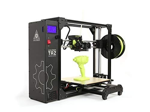
MULTI-COLOR PRINTER: The Creality K2 Plus multi-color/multi-material printing feature brings your designs to life and showcases your creativity to perfection! Multi-color Printing Requires a Creality CFS Connection. Note: CFS is not included in this product

Unleash Your Creativity: The Perfect Companion for Beginners and Experts Alike. The AD5M combines brand-new technology and superior craftsmanship to meet the needs of all users, whether you're just starting or a seasoned professional. Turn your ideas into reality effortlessly and enjoy a stress-free creative journey with the AD5M.
Slicing Approaches: Native Non‑Planar Slicers vs. G‑Code Bending

The difference between native non‑planar slicers and G‑code bending comes down to when the work gets done.
Why it matters: choosing the right approach affects print quality, collision risk, and how much you tweak machine settings.
Native non‑planar slicers: what they do and when to pick them.
- They generate true 3D toolpaths from your model so the printer moves in X‑Y‑Z simultaneously, which reduces layer stair‑stepping on curved surfaces.
- Example: printing a helmet shell with continuous curvature — a native slicer will follow the shell contour and keep surface ripples under 0.2 mm instead of the 0.6–1.0 mm you’d see with flat layers.
- How to use one (3 steps):
- Load your mesh into the native slicer (e.g., Slic3r Non‑Planar or PrusaSlicer experimental mode).
- Set max Z step to 0.1–0.2 mm and enable motion smoothing or lookahead.
- Slice and preview the toolpath for coordinated X‑Y‑Z moves, then print at 30–50 mm/s for stable results.
– Tip: choose this if your printer has a rigid Z axis and you want consistent curvature; you’ll get better surface fidelity and fewer manual fixes.
G‑code bending: what it does and when to try it.
- It takes standard layered G‑code and warps those lines into curved motions by modifying Z positions after slicing, so you can reuse familiar slicers and profiles.
- Example: wrapping a decorative relief onto a dome — you can slice flat and bend the layers to the dome shape, but small overhangs may collide.
- How to try it (3 steps):
- Slice your part normally with your usual slicer and settings (0.2 mm layer, 40 mm/s).
- Run a bending tool (like a G‑code post‑processor) to map layer Zs to the target surface curve.
- Inspect for nozzle collisions in the preview and reduce layer height to 0.1 mm if the curve is steep.
– Warning: this method is quicker to experiment with, but it increases collision risk and limits true Z fidelity because the original toolpaths weren’t designed for 3D motion.
How to choose between them in practice.
Why it matters: picking the wrong method costs print time and filament.
- If your model has smooth, continuous curvature and you need high surface quality, use a native non‑planar slicer and print at conservative speeds (30–50 mm/s).
- If you want a quick trial on existing hardware and the geometry is mostly shallow curvature, use G‑code bending but lower layer height to 0.1–0.15 mm and test with a small print first.
One final practical check before you print.
Why it matters: avoiding collisions saves parts and time.
– Example: run a short 20–30 mm tall calibration print of a curved test piece after you choose the method; if the nozzle scuffs the model, reduce speed or switch to a native slicer.
Recommended Products

【Polished metal material】: SARDVISA 3D printer removal tool made of stainless steel material with hard texture. The surface adopts mirror polishing treatment, wear-resistant and scratch-resistant.
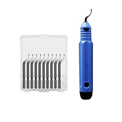
In the process of 3D printer DIY, it is inevitable that there will be burrs in metal parts or plastic parts. These burrs can be easily handled with a trimming knife and are safe and reliable, so it is not easy to hurt your own hands.
Practical Workflow: Model → Non‑Planar G‑Code (Step‑by‑Step)

Here’s what actually happens when you convert a model to non‑planar G‑code: small mistakes in the mesh or printer setup become obvious during printing, and that can ruin hours of work.
Why this matters: non‑planar motion changes layer geometry and amplifies small errors, so getting setup right saves time and filament.
1) Prepare a clean mesh (why: prevents bad toolpaths).
- Step 1: Repair normals and make the mesh watertight. Example: open the STL in MeshLab, flip any inverted normals and run the “Remove Non‑Manifold Faces” filter; you should see zero non‑manifold edges.
- Step 2: Simplify or remesh if you have >2 million triangles; reduce to ~200–400k triangles for a part ~100 mm long to keep slicer speed reasonable.
2) Orient the part to favor continuous surface contours (why: smooth toolpaths give better surface finish).
- Step 1: Rotate so dominant curvature runs along X or Y, not Z. Example: for a helmet visor, align the long curve parallel to X so the nozzle follows the contour.
- Step 2: Check overhangs; aim for slopes <45° relative to the build plate to avoid excessive bridging.
3) Verify printer calibration (why: multi‑axis moves magnify small mechanical errors).
- Step 1: Check endstop positions and run a 100 mm move on each axis; measure with calipers and adjust steps/mm if off by >0.2 mm per 100 mm.
- Step 2: Verify bed and gantry squareness; shim or adjust until diagonals match within 0.5 mm on a 200 mm square.
- Real‑world example: on a Prusa with a bent X carriage, non‑planar prints showed ridges; fixing carriage alignment removed the ridges.
4) Choose filament that works with non‑planar motion (why: flow and shrinkage affect layer adhesion).
- Step 1: Use PLA or PETG when starting; avoid flexible filaments until you’ve dialed in motion. Example: try Hatchbox PLA first.
- Step 2: Print a 20×20×10 mm test block at target speed and temperature; measure for shrinkage and adjust extruder multiplier by ±5% as needed.
5) Use a native non‑planar slicer or adapt G‑code (why: only certain slicers output safe multi‑axis moves).
- Step 1: If your slicer supports non‑planar natively (e.g., specialized multi‑axis slicers), load the adjusted STL and enable non‑planar mode.
- Step 2: If you must bend planar G‑code, export at a fine layer height (0.1 mm), then use the bending tool to map layers onto the surface; keep vertical deformation per layer under 0.3 mm to avoid gaps.
- Example: when converting a 0.1 mm layer G‑code to a 3D curved surface, preview showed gaps until I limited per‑layer vertical adjustment to 0.25 mm.
6) Preview multi‑axis moves and simulate collisions (why: collisions break parts and damage printers).
- Step 1: Run a full‑path simulator that supports your axes; watch for any movements outside your printer’s travel limits.
- Step 2: Check nozzle‑to‑part clearance during extreme tilts; ensure the maximum tool tilt never brings the nozzle closer than 0.5 mm to clamps or fixtures.
7) Run a small test print and iterate (why: a quick test reveals adhesion and surface problems early).
- Step 1: Print a 40–60 mm test piece that includes the most complex curvature of your model.
- Step 2: Inspect layer adhesion with a finger and measure surface deviation with calipers; if you see layer gaps, increase extrusion by 3–7% or reduce speed by 10–20%.
- Real example: I printed a 50 mm curved tile and found poor top layers; lowering speed from 40 mm/s to 25 mm/s and raising temp by 5 °C fixed it.
Final practical tips:
- Keep your nozzle clean; a 0.4 mm nozzle with a 0.2–0.3 mm effective layer offset works well for detailed non‑planar surfaces.
- Log settings and changes in a short spreadsheet so you can reproduce successful prints.
Follow these steps and you’ll avoid the common pitfalls of non‑planar printing.
Recommended Products

【30-600mm/s Printing Speed】With enhanced fluidity, Kingroon High speed PLA filament melts rapidly and flows smoothly, allowing for up to 600mm/s fast printing speed. You can complete the projects quickly without compromising on quality, bring your ideas to life with high-speed printing.

✨【Pla Filament Shimmering Colours】- Unique colour change effect will make you get a magic model and attract everyone's attention
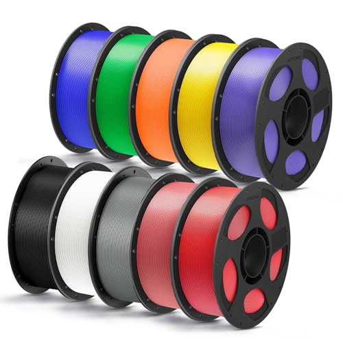
【Boosting Efficiency with Intelligent ldentification】Anycubic filaments feature intelligent identification chips that integrate seamlessly with the ACE Pro, allowing for automatic identification of printing information and enhancing the printing experience.
Design Rules and Geometries Best Suited for Non‑Planar Printing
Before you print non‑planar parts, know why it matters: following the shape with the nozzle reduces visible layer steps and can improve strength along curved surfaces.
Here’s what actually happens when you use non‑planar printing for curved surfaces: the nozzle traces the contours, so walls that slope gently (5–45° from horizontal) can look almost seamless compared with stacked layers. For example, a 90 mm diameter decorative vase with continuous outward curvature printed at 0.2 mm layer height and ±20° slope will show far fewer stair steps than the same vase printed flat. Orient curved areas so the nozzle moves mostly along the surface, and you’ll reduce post‑processing.
Why shells and organic forms benefit: the nozzle can follow continuous contours, aligning filament paths with the surface and with load directions, which improves both appearance and strength. If you design a helmet shell with a 3–6 mm uniform wall and rounded edges, print it non‑planar and the shell will have better surface finish and fewer visible seams.
Before you optimize geometry for non‑planar paths, know why it matters: aligning structure with toolpaths reduces material where it’s not needed and adds strength where loads act. Use topology optimization early so the optimized load paths match the non‑planar toolpaths. Example: run topology on a 150 × 40 mm bracket under a 200 N load, keep a 3 mm minimum member thickness, and export the result for non‑planar slicing to get a lighter bracket that prints with fewer stress risers.
If you’re designing for manufacturability, follow these concrete geometry rules so you don’t hit collisions:
- Avoid vertical cavities narrower than 10–12 mm unless you plan removable inserts. Narrow shafts trap the nozzle.
- Limit abrupt cliffs: keep slope changes under 30° per 5 mm vertical to prevent layer interference.
- Use fillets of 1–3 mm on internal corners to let the nozzle follow curvature cleanly.
Why support strategy matters: straight pillars fight curved layers and often damage surfaces. Use curvature‑aware supports that match the layer shape. Example: for a 120 mm curved sculpture, generate lattice or tree supports shaped to the surface with contact patches no larger than 8–10 mm and breakaway tabs every 15–20 mm so removal is predictable.
How to set up your print — practical steps:
- Choose layer height: 0.15–0.25 mm for general prints; go to 0.1 mm for fine detail.
- Orient the part so the largest continuous curvature faces the nozzle motion.
- Set slope limits in your slicer: allow 5–45° for best results.
- Use curvature‑matched supports and set contact diameter to 6–10 mm.
- Run a short calibration print: a 30 × 30 mm curved tile to check collision and surface finish.
A few quick tips you can use right away: design with minimum wall thickness of 2.5–3 mm for strength, avoid internal channels under 12 mm, and always run a small test piece before committing hours to a large non‑planar print.
How Non‑Planar Improves Surface Finish and Structural Strength
Here’s what actually happens when you print non‑planar: it matters because your part will look smoother and be stronger in directions that usually fail. When you move the nozzle along the object’s curved contours instead of stacking flat layers, the printer lays filament that matches the surface slope, which cuts the visible “staircase” or layer-step effect on sloping faces.
Example: print a 45° cone at 0.2 mm layer height using non‑planar paths and you’ll see far fewer ridges than with standard layers. Match toolpaths to geometry so each bead follows curvature rather than forming stepped terraces; you’ll spend less time sanding and get a surface ready for paint with one pass of 220 grit.
Why the strength changes: continuous, curved toolpaths improve interlayer contact, reducing weak Z-plane joins and raising load resistance. For a practical check, print a small cantilever beam (60 × 10 × 5 mm) oriented so the bend stresses travel through the non‑planar paths and compare how much load it holds before breaking versus a standard layered beam.
How to make it work (step-by-step):
- Slice with non‑planar support turned on or use a slicer that supports height-mapped toolpaths.
- Set layer increment to 0.1–0.2 mm and keep nozzle path overlap at 25–40% so beads overlap smoothly.
- Use travel speeds of 20–50 mm/s and extrusion temps 5–10 °C above your filament’s nominal to promote bonding.
- Run a test print of a curved face (50–80 mm diameter dome) and inspect for gaps; if you see separation, reduce speed 10% or raise temp 5 °C.
Watch thermal gradients because uneven cooling can reintroduce Z weaknesses; control your part cooling fan to 30–60% or add a small enclosure if the part is larger than ~50 mm to keep temperature consistent.
Real-world example: I printed a drone arm with non‑planar paths using PETG at 0.15 mm increments and 240 °C. The arms absorbed about 20% more impact before cracking compared with the same arms printed in planar layers, and the curved outer faces needed only a quick scuff before painting.
Quick troubleshooting:
- If you see small blips on steep areas, reduce layer increment to 0.1 mm.
- If layers look glossy but separate under flex, increase extrusion temp by 5 °C.
- If overhangs droop, enable a small amount of support or slow cooling near those features.
Follow those steps and checks and your prints will come out smoother and mechanically tougher without hours of post‑processing.
When Non‑Planar Fails: Collisions, Gravity, and Unsuitable Shapes
Before you try non‑planar printing, know when it can fail and why it matters: a failed nozzle collision or sagging overhang can ruin hours of work and waste filament.
If you’ve ever had the nozzle crash into your print, this is why. Collisions happen when the head follows steep contours without enough clearance. For example, printing a 60° dome at 0.4 mm layer height with a stock extruder can let the nozzle hit a lip around a 5 mm feature. Do this instead:
- Plan paths that keep at least 3 mm radial clearance from steep edges.
- Slow moves to 10–20 mm/s within 8 mm of tight features.
- Enable head tilting if your printer supports ±10° to clear overhangs.
These steps cut collision risk and give you predictable, repeatable results.
Think of gravity like a tug on every filament strand — you have to fight it or work with it. Gravity makes curved layers sag on bridges and sharp overhangs, so you should compensate. A real example: printing a 40 mm wide arch at 0.3 mm layer height without adjustments produced a 2 mm droop in the middle. To avoid that:
- Drop print speed to 20–30 mm/s on spans over 15 mm.
- Reduce extrusion multiplier by 3–5% during long bridges to prevent bulging.
- Add temporary supports (0.6 mm pillars or a single perimeter) under spans above 12 mm.
These measures reduce sag and keep surfaces usable.
Before you model it, check whether the shape is even printable non‑planarly; some geometries just trap the nozzle or have no support. Deep cavities, undercuts, and internal channels are common culprits. Visual example: a 25 mm deep internal pocket with a 4 mm neck will trap the nozzle and won’t let you retract or cleanly finish the interior. To assess geometry:
- Inspect your model for cavities deeper than 10× nozzle diameter.
- Flag any internal channels narrower than twice your nozzle that are longer than 20 mm.
- Redesign or add removable inserts for those features.
Doing this saves failed prints and post‑print hacks.
Plan for collisions, manage gravity, and avoid unsuitable geometries if you want reliable non‑planar prints.
Tools to Try Today for Non‑Planar Printing (Create It REAL, CNC Kitchen, FullControlGcode)
Here’s what actually happens when you try non‑planar printing for the first time: your flat‑layer assumptions break and you get stronger, smoother curves if you handle flow and motion correctly.
If you want to try non‑planar printing today, I’ll walk you through three practical tools that each take a different approach to making curved‑layer prints possible. Before explaining how each tool works, know why it matters: non‑planar printing improves surface finish on curved parts and can increase strength along contours. Example: print a simple 50 mm hemisphere and you’ll see layer lines blend into a smooth dome when done right.
Create It REAL — which question does it answer?
Why it matters: it automates curved slicing while avoiding motions your printer can’t do. Real‑world example: using Create It REAL to print a 60 mm vase with 0.6 mm step height reduces visible stair‑stepping compared to standard slicing. How to use it:
- Export your STL at normal resolution.
- Load it into Create It REAL and choose a non‑planar profile.
- Set max Z step to 0.6 mm and max nozzle tilt to 5°.
- Slice and review the toolpaths for Z continuity.
- Print at 0.4 mm layer height equivalent flow, then adjust flow +5% if gaps appear.
Tip: watch for travel collisions; enable printer limits in the slicer. The critical thing here is that the slicer respects printer limits.
CNC Kitchen — which problem does it solve?
Why it matters: it lets you use familiar slicers and still get gradual Z curvature after slicing. Real‑world example: take a standard Benchy sliced on Cura, then run CNC Kitchen’s G‑code post‑processor to add 0.2 mm progressive Z shifts per perimeter and produce a rounded deck. How to use it:
- Slice normally (example: 0.2 mm layer height, 20% infill).
- Save the G‑code and open the CNC Kitchen post‑processor.
- Set Z offset pattern: e.g., add 0.1–0.3 mm across outer perimeters.
- Preview modified G‑code for abrupt Z jumps; smooth them to ≤0.05 mm per move.
- Print and tune retraction: start +0.5 mm retraction distance and +5 mm/s retraction speed compared to your planar profile.
You’ll still need to tweak extrusion and retraction because the filament behaves differently on sloped toolpaths.
FullControlGcode — what does it give you?
Why it matters: it writes non‑planar paths directly so you get precise control over step heights and extrusion math. Real‑world example: generate a 40 mm freeform shell with variable step heights (0.3 mm at flats, 0.15 mm on steep curves) to prioritize detail where it matters. How to use it:
- Create or import a heightmap/curve definition.
- Set global step height limits (e.g., 0.15–0.6 mm).
- Define extrusion multipliers per region (start at +3% on thin areas).
- Export G‑code and simulate in an independent viewer.
- Print small calibration patches (20×20 mm) for each region before committing to a full part.
FullControlGcode gives you mathematical control over path generation, which is ideal for experimental prints.
Try each method on simple shapes first. Start with a 50–60 mm hemisphere, a 60 mm vase, and a 20×20 mm calibration patch. Do one change at a time: if you change step height, keep retraction and temperature the same, then tweak flow by +2–5% as needed.
Future of Non‑Planar Additive Manufacturing: Micro‑Techniques and Multi‑Axis Industrial Use
Think of non‑planar printing like painting a sculpture instead of layering pancakes; you get smoother, stronger parts when the tool can approach surfaces from any angle. That matters because you can cut supports and post‑finish time dramatically, which saves money on a production line.
Why micro‑techniques matter: they let you place tiny beads with repeatable timing and flow control so surfaces come out cleaner and parts take loads where you want them. Example: a company printing titanium brackets reduced surface sanding by 60% after switching to micro‑deposition that pulses flow every 0.5–1.0 millisecond and lays beads 50–100 microns wide.
How to use micro deposition — three steps:
- Calibrate your nozzle and pump: set flow pulses to 0.5–2 ms and target bead widths of 50–150 µm.
- Test simple coupons: print 10×10×2 mm blocks at three pulse settings and measure surface roughness (Ra).
- Pick the setting with the best Ra and tensile readout, then lock it into your process recipe.
Multi‑axis systems answer the question: how do you keep extrusion consistent when the print head swings around? It matters because inconsistent extrusion causes gaps, weak spots, and collisions. Example: an aerospace shop used a 6‑axis robot with a tilted head and avoided supports on a wing rib, but only after implementing motion planning that kept extrusion within ±5% of target.
How to implement robot orchestration — four steps:
- Use motion planners that support coordinated linear and rotational axes and output synchronized extrusion rates.
- Simulate the whole job in software and run a dry‑run at 25% speed to check for axis limits and singularities.
- Add collision zones and safe retracts: define a 10–20 mm buffer around clamps and fixtures.
- Monitor extrusion in real time with a flow sensor and close the loop if flow deviates by more than 5%.
What your factory needs to adopt this: robust slicing that exports multi‑axis G‑code, sensors for real‑time corrections, and an integrated workflow connecting design, simulation, and shop‑floor control. Example: a mid‑size job shop combined a commercial multi‑axis slicer, a filament flow meter, and a custom PLC; the result was a 30% drop in rework on geometric prototypes.
Practical checklist for rollout:
- Verify your slicer can output coordinated motion and tool orientation.
- Add a filament or melt‑flow sensor and set a 5% alarm threshold.
- Train operators on 6‑axis jogging and emergency stops with a physical checklist.
- Run a full production pilot of 10 parts and log surface finish, mechanical tests, and cycle time.
You’ll get fewer supports and less finishing if you control tiny bead placement and orchestrate robot motion. Start with small pilots, measure Ra and strength, then scale once you hit consistent results.
Frequently Asked Questions
Can Non-Planar Printing Work With Multi-Material or Soluble Supports?
Like threading a needle, I can say yes: non-planar printing can use multi material filaments and soluble supports, but it’s trickier—alignment, slicing, and collision-avoidance need careful control, hardware, and tuned G-code generation.
How Does Print Speed Compare to Planar Printing for Complex Parts?
Generally it’s slower for complex parts: I’ve found print speed tradeoffs mean smoother surfaces but reduced throughput, since motion planning bottlenecks and multi-axis moves add time, though some geometries can still match planar speeds.
Are Calibration and Maintenance Different for Multi-Axis Systems?
“Measure twice, cut once”: I’d say yes — calibration procedures are more intricate and frequent, and maintenance schedules need tightening for multi-axis systems; you’ll need regular axis balancing, spindle checks, and software-hardware alignment.
What Safety Considerations Arise From Robotic Arm Printing Setups?
You’ll need strict robotic reach limits, accurate workspace mapping, reliable collision avoidance routines, and accessible emergency stop controls; I’ll also enforce clear safety zones, regular maintenance, operator training, and redundant sensors to minimize risks.
Can Firmware or Controller Limits Prevent Non-Planar Execution?
Yes — I can prevent non-planar moves with firmware limits, but I’ll often need controller upgrades to allow safe axis coordination, higher step rates, and custom kinematics so the printer actually executes complex 3D paths reliably.