As an Amazon Associate, we earn from qualifying purchases. Some links on this site are affiliate links at no extra cost to you. Our recommendations are based on thorough research and editorial judgment.

Flow Rate Calibration: The Mathematics Behind Perfect Extrusion
You’ve just sliced a new part, watched the first layer print, and the single‑wall perimeter looks too thin or too fat — you’re staring at a caliper wondering which setting to change.
The exact problem is: your prints don’t hit the target wall thickness, leaving weak, sloppy, or oversized perimeters. Most people blame the slicer profile or nozzle size and skip the measured flow correction that actually fixes dimensional extrusion.
This article shows step‑by‑step how to measure mean wall thickness, compute the precise flow multiplier (NewFlow = CurrentFlow × TargetWall ÷ MeasuredWall), and apply it in your slicer so single‑wall prints match the target thickness.
It also tells you what to check first (E‑steps, extruder tension, pressure advance) and how to retest until within tolerance.
It’s easier than you think.
Key Takeaways
Before you measure wall thickness, know why it matters: accurate wall thickness tells you whether your printer is extruding the right amount, and that keeps prints dimensionally correct and strong.
Here’s what actually happens when you take caliper readings: small positioning errors change the number by a few hundredths of a millimeter, so averaging reduces random error. Example: you measure four perpendicular spots around a cylinder wall and get 0.42, 0.40, 0.43, 0.41 mm; the average is 0.415 mm and is closer to the true value than any single reading.
1) Take at least four caliper readings spaced evenly around the wall, perpendicular to the surface.
2) Record each reading and calculate the mean.
3) Use that mean as your MeasuredMeanWall.
Be careful to place the calipers straight and avoid squeezing; a steady hand keeps variation under 0.02 mm.
Why you should correct flow: the slicer extrusion multiplier directly scales how much filament the printer thinks to push, so a small math change fixes big errors. Example: your target wall is 0.40 mm and your measured mean is 0.44 mm; without correction your prints will be over-extruded and look squishy.
1) Compute CorrectedFlow = CurrentFlow × (TargetWall ÷ MeasuredMeanWall).
2) Enter that number into your slicer’s extrusion multiplier (or flow percentage).
3) Print the single-wall test again.
If CurrentFlow is 1.00, TargetWall 0.40 mm, and MeasuredMeanWall 0.44 mm, CorrectedFlow = 1.00 × (0.40 ÷ 0.44) = 0.909 (90.9%).
Before you iterate, here’s why iteration matters: tiny mechanical or temperature factors shift extrusion, so you need to recheck after each adjustment. Example: you change flow from 100% to 90.9% and reprint the test wall; if the new measured wall is 0.399 mm you’re within tolerance.
1) Reprint the single-wall test after changing the flow.
2) Measure the wall mean again with multiple perpendicular readings.
3) If the mean is outside ±0.02 mm of the target, repeat the correction calculation and reprint.
Stop when measured wall is within ±0.02 mm of your target.
Make sure the machine is stable before you change flow because other errors will mask your calibration. Example: if E‑steps are off by 2% you’ll chase the wrong number and never settle.
1) Verify E‑steps using a marked filament test and adjust if the measured extrusion over 100 mm differs from 100 mm.
2) Check extruder tension so the filament feeds smoothly without grinding; tighten until it grips but doesn’t deform the filament.
3) Confirm temperature is within ±5°C of your normal printing temp and use consistent filament spool conditions.
4) If your printer uses pressure advance or linear advance, tune that separately so pressure-induced over/under extrusion isn’t mistaken for flow error.
Save your work because filament and settings change extrusion behavior. Example: PETG from a new spool might print a touch wetter than the old spool of the same brand.
1) Save the calibrated flow value into a per‑filament profile in your slicer.
2) When you change spools, hotend, nozzle, or major slicer settings (retraction, layer height), print the single-wall test and retest flow.
That way you’ll avoid surprises and maintain consistent part dimensions.
Quick Math: Calculate the New Flow Rate (Worked Example)
Here’s what actually happens when you adjust flow for a slicer: getting the number right makes your walls match the design and reduces post-print sanding.
Why this matters: if your walls print too thick or thin, parts won’t fit or look right.
Real example: you expect a wall of 0.40 mm but your caliper shows 0.45 mm. Picture a small box with one side visibly puffed out by about the width of a grain of rice.
How to calculate the new flow (steps):
- Measure multiple spots. Take at least five caliper readings across the same wall and average them. This reduces random error.
- Use the formula: new flow = (expected ÷ measured) × current flow. Plug in numbers: 0.40 ÷ 0.45 × 1.00 = 0.889.
- Enter the result as a percentage in your slicer: about 88.9%.
- Reprint the same test piece and measure again to confirm you’re within a few percent.
Why you take multiple readings: small caliper errors swing the result. For example, if one reading is 0.44 and another 0.46, the average 0.45 is steadier than any single value.
Quick tip: round sensibly — use 88.5% or 89% if your slicer only accepts whole numbers.
Set Up a Single‑Wall Test Print for Flow Calibration

Before you set up a single-wall test print, know why this matters: you’ll measure extrusion error directly so your prints get the right wall thickness.
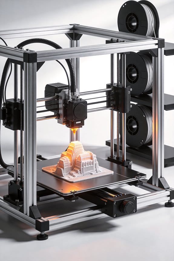
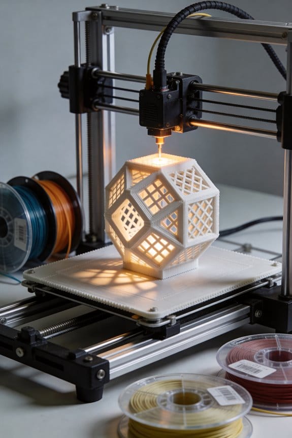
Here’s a simple way to prepare a model that shows extrusion only. Pick a hollow 20 mm cube or a 20 mm tall, 20 mm diameter cylinder with a single perimeter in your slicer; I use a 0.4 mm nozzle, so set the wall line count to 1 and the extrusion width to 0.48 mm (120% of nozzle). Example: a 20 mm cube sliced with 0.2 mm layer height, 50 mm/s print speed, and a 0.4 mm nozzle gives clear, measurable walls.
Why this single-wall test matters: you want to isolate filament flow from infill and multiple walls so your calculation is accurate. For instance, when I calibrated PETG using this cube, the single wall revealed a 6% over-extrusion that was invisible in regular prints.
1) Set slicer settings (how)
- Set flow to 100% in the slicer.
- Use a single perimeter (wall count = 1).
- Set layer height to 0.2 mm and nozzle size to 0.4 mm.
- Set extrusion width to 0.48 mm (or 120% of nozzle) unless your slicer auto-calculates it.
- Disable infill and top/bottom layers so only the single wall prints.
- Print speed: 40–60 mm/s.
- Retraction: keep your normal retraction for travel moves.
Example: Cura profile — Wall Line Count = 1, Line Width = 0.48 mm, Flow = 100%, Speed = 50 mm/s.
Why bed prep matters: an uneven first layer changes wall width, making your measurement wrong. I once got a bad calibration because the first layer squished differently across the cube.
2) Prepare the bed (how)
- Level the bed with a feeler or paper so the nozzle is consistently 0.1–0.2 mm above the bed at all corners.
- Clean the bed with isopropyl alcohol and remove filament residue.
- Use a thin glue stick or PET tape only if you normally use them; keep the same adhesion method you print with.
Example: On a glass bed, I wipe with 90% IPA, then apply a thin, even layer of glue stick for PLA.
Why cooling and stabilization matter: thermal swelling or soft filament can change wall thickness while measuring, giving wrong flow values.
3) Cooling and print strategy (how)
- Enable part cooling fan at 100% after the first 2 layers for PLA; for PETG use 30–50% to avoid layer adhesion issues.
- Print one object at a time and let it cool on the bed for 5–10 minutes before removing.
- If your printer heats the bed, let the bed reach ambient or 30–40°C before measuring to avoid dimensional drift.
Example: With PETG at 240°C and 40% fan, I let the printed cube cool 7 minutes and the walls stayed stable for calipers.
Why measuring gives you the flow factor: comparing the actual wall thickness to the expected extrusion width tells you the percent adjustment needed.
4) Measure and adjust flow (how)
- Use digital calipers and measure wall thickness at four sides near the middle of the height; avoid top and bottom layers.
- Average the four measurements.
- Calculate new flow: NewFlow% = CurrentFlow% × (ExpectedWall / MeasuredWall). For a 0.48 mm expected wall and a measured 0.51 mm, NewFlow% = 100 × (0.48 / 0.51) = 94.1%.
- Update flow in your slicer or printer by that percentage and reprint the test.
Example: Measured 0.44 mm with expected 0.48 mm → NewFlow% = 109% (100 × 0.48/0.44).
Why repeat once matters: small errors in measurement or temperature can mislead you, so verify with one more print.
5) Verify once more (how)
- Print the same single-wall model with the adjusted flow.
- Measure again using the same four spots and average.
- If the result is within ±0.02 mm of the expected wall, stop. If not, repeat the adjustment.
Example: After one adjustment I got 0.479 mm average on the second print, which is within tolerance.
Quick checklist before you start:
- Model: 20 mm cube or 20×20 mm cylinder, single perimeter.
- Slicer: Flow 100%, line width 0.48 mm, layer height 0.2 mm, wall count = 1, no infill.
- Print: 40–60 mm/s, normal retraction, appropriate cooling.
- Bed: leveled, clean, consistent adhesion method.
- Measure: 4 spots with calipers, average, compute new flow.
If you follow those steps, your extrusion multiplier will be grounded in measurement, not guesswork.
Prerequisites: E‑Steps, Tension, Pressure Advance, and Tools

Before you run any flow rate calibration, you need to know which prerequisites directly change extrusion accuracy. Why it matters: if these are off, every flow adjustment you make will be wrong. For example, I once ran a calibration with sloppy E‑steps and got blobs on the entire right side of a Benchy.
1) How do you verify E‑steps (extruder steps/mm)?
Why it matters: incorrect steps per millimeter skews every filament measurement you take.
Steps:
- Heat the hotend to printing temperature for your filament.
- Mark the filament 120 mm above the entry to the extruder.
- Command the extruder to feed 100 mm at a slow speed (e.g., 100 mm/min).
- Measure the remaining distance from the mark to the entry; if it’s 20 mm, steps are correct.
- If not, calculate new E‑steps: new = current × (commanded mm / actual fed mm).
Real-world example: on my Bowden PETG setup I measured 108 mm fed when commanding 100 mm, so I multiplied the E‑steps by 100/108 and saved it.
2) How do you check extruder tension?
Why it matters: slipping or crushing the filament changes feed and nozzle pressure.
Steps:
- Loosen the tension, then load filament and try to extrude 50 mm by hand; it should move smoothly with light pressure.
- Tighten the tension until you can’t easily push filament by hand but the motor can still pull it.
- Run a 50 mm extrusion at low speed and watch for slipping marks on the filament or filament grinding.
Real-world example: on a direct-drive PLA print I saw thin shaved grooves after overtightening, so I backed the spring off one full turn and the grooves disappeared.
3) Why tune pressure advance (or linear advance)?
Why it matters: it compensates for melt pressure so your start/stop lines and corners look clean.
Steps:
- Pick a test print with lots of stops/starts, like a single-wall square, and print at a moderate speed (40–60 mm/s).
- Run a sweep of pressure advance values (e.g., 0.00, 0.02, 0.04, 0.06) and inspect the corners for blobbing or gaps.
- Choose the value that gives the cleanest corner transitions.
Real-world example: on TPU I found 0.10 caused under-extrusion at ends, while 0.04 eliminated the blobs without gaps.
4) How do you control filament hygroscopy?
Why it matters: moisture changes filament diameter and makes extrusion inconsistent.
Steps:
- Store filament in a dry box or sealed bag with silica packs when not in use.
- If filament is old or prints stringy, dry it: 4 hours at 50–60°C for PLA, 6–8 hours at 60–70°C for PETG/ABS, longer for nylon.
Real-world example: my spool of hygroscopic nylon printed fine after 24 hours at 70°C; before drying it steamed and bubbled.
5) Which tools and test setup should you prepare?
Why it matters: accurate measurements give reliable flow adjustments.
Steps:
- Get digital calipers that measure to 0.01 mm.
- Use a rigid test print surface and print a single-wall cube or a 20 mm calibration cube for flow tuning.
- Keep a clean filament path and consistent print temperature for each test.
Real-world example: I used cheap calipers once and got an erroneous 1.2% flow change; with better calipers the correction was just 0.3%.
Do these checks first, then run your flow rate calibration.
Recommended Products

MULTI-COLOR PRINTER: The Creality K2 Plus multi-color/multi-material printing feature brings your designs to life and showcases your creativity to perfection! Multi-color Printing Requires a Creality CFS Connection. Note: CFS is not included in this product

Measures tension in cables to check for proper setup in sail rigging and supporting cables for large tents, radio towers, and other structures

NECK TENSION GAUGE - Inspection tool to quickly and accurately screen/sort a batch of brass before your bullet seating operation
Measure Wall Thickness: Tools, Technique, and Averaging

Here’s what actually happens when you measure printed wall thickness: your flow calculation will be wrong if the thickness number is wrong.
Why this matters: the flow rate you set depends directly on the measured wall thickness, so an error there skews every print. Example: a 0.1 mm error on a 0.4 mm wall is a 25% flow error that shows up as gaps or blobs.
1) Gather tools and prepare
- Use a calibrated digital caliper for the basic readings.
- If you have access, use a non‑contact profilometer or optical comparator for verification.
- If you want tactile confirmation, use a probe (CMM or touch probe on your printer works).
Example: on my cheap 0.4 mm single‑wall test cube, I used a calibrated Mitutoyo caliper and also ran one scan on a lab profilometer to confirm.
2) Take measurements step by step (do this exactly)
- Print a single‑wall test piece with known dimensions (e.g., 20×20 mm square, 0.4 mm expected wall).
- Let the part cool to room temperature for 15–30 minutes to avoid thermal expansion errors.
- Using the caliper, take at least 6 measurements around the perimeter: top, bottom, left, right, and two midpoints.
- If you have a profilometer, run a surface scan across one side to map local variations; save the profile.
- If using a tactile probe, touch three points per wall section to confirm local height and any bumps.
Example: I measured six points on a 0.4 mm wall: 0.38, 0.39, 0.42, 0.40, 0.37, 0.41 mm.
3) Process the numbers and get the number you’ll use
- Discard clear outliers: drop any reading that differs from the median by more than 2× the standard deviation.
- Average the remaining readings to get the mean wall thickness.
- Record the mean, the number of samples, and the standard deviation.
Example: from the six readings above drop 0.37 as an outlier, average the rest (0.38+0.39+0.42+0.40+0.41)/5 = 0.4 mm.
Quick tips and traps
- Calibrate the caliper before use; a 0.05 mm offset ruins the flow math.
- Measure after cooling; warm plastic measures larger.
- If the profilometer and caliper disagree by >0.05 mm, trust the profilometer for local defects.
Example: a profilometer scan once revealed a 0.12 mm ridge near the start‑stop that none of my five caliper points hit.
Final actionable number
– Use the averaged mean thickness as the input to your flow calculation and note the standard deviation as the expected variability.
Recommended Products

Absolute Origin Calibration: The iGAGING Absolute Origin Electronic heavy duty digital caliper retains the set zero reference point even after the caliper is off. This large thickness or diameter measuring tool feature saves time, as well as ensures consistent and accurate inch/metric measurements at 12", 24", or 40".

High Accuracy and Precision - Starrett calipers are excellent tools in providing accurate markings to maintain exact measurements from various work applications.

【Precise Measurement】Measuring range :0-1000mm; Resolution: 0.0005in/0.01mm
Apply the Calculation to Your Slicer Settings (PrusaSlicer, IdeaMaker, Simplify3D, OrcaSlicer)

Before you apply the corrected flow rate, understand why it matters: if your slicer’s extrusion value is off, your walls will print too thin or too fat and fit won’t match design.
Here’s what actually happens when you enter the new number in each slicer: the slicer scales extrusion so the printer pushes filament to match your measured wall thickness.
PrusaSlicer — Where to put it and what to expect
Why this matters: Changing the extrusion multiplier here changes the actual filament per mm the slicer outputs, so your calibrated wall thickness will print correctly.
Example: I measured 0.45 mm average wall instead of 0.40 mm, so my corrected flow is 0.40 / 0.45 = 0.888. I typed 0.888 into PrusaSlicer.
Steps:
- Open Filament Settings → Filament Overrides.
- Edit Extrusion Multiplier to your corrected number (for example, 0.888).
- Save as a filament profile so you can reuse it.
What to expect: perimeter widths will match closer to your target on future prints.
IdeaMaker — Where to put it and what to expect
Why this matters: IdeaMaker’s Flowrate setting applies per-extruder scaling, so wrong values give gap or bulge issues on prints.
Example: A PLA roll from a new batch measured 1.05× the expected, so I set Flowrate to 0.952 (1 / 1.05) in the profile.
Steps:
- Open Printer Profile → Primary Extruder → Filament Settings.
- Change Flowrate to the corrected decimal (0.952 in the example).
- Save to a per-filament template if you use multiple filaments.
What to expect: reprints of calibration cubes or small parts should show corrected wall thickness and better dimensional accuracy.
Simplify3D — Where to put it and what to expect
Why this matters: The Extrusion Multiplier here is applied per-process, so it’s perfect for tuning a specific print without changing global settings.
Example: For a specific print that needed slightly more filament I set Extrusion Multiplier to 1.03 in that process.
Steps:
- Edit your Process → Select Extruder tab.
- Enter the corrected Extrusion Multiplier (e.g., 1.03).
- Duplicate the process if you want different multipliers for different jobs.
What to expect: that single process will print with adjusted extrusion while others remain unchanged.
OrcaSlicer — Where to put it and what to expect
Why this matters: OrcaSlicer accepts a Flow Ratio or block-based adjustments, letting you tweak either globally or for specific print sections.
Example: I used Flow Ratio 0.95 for a flexible TPU spool and added a +0.02 extrusion multiplier block for bridging areas.
Steps:
- Open Filament or Print Settings → Flow Ratio (or Extrusion Multiplier block).
- Enter your corrected ratio (e.g., 0.95) or add a block for localized changes.
- Save the profile or the modifier block for reuse.
What to expect: overall extrusion will match your calibration, and specific blocks override where needed.
General tips and cautions
Why this matters: If you don’t account for filament variability, a good calibration can be undone by a new roll or humidity change.
Example: Two PLA spools from different manufacturers required 0.97 vs 1.03 flow values; I labeled profiles by spool.
Steps:
- Label filament profiles with measured flow values.
- Test with a small calibration print after changing spools.
- Don’t change firmware E-steps unless every filament consistently needs the same correction.
What to expect: consistent dimensions when you pick the matching profile for a spool, and fewer surprises at first layer.
End result: input the corrected decimal into the slicer field that matches your software, save it to the filament or process profile, then print a quick calibration part to confirm the walls now match the intended thickness.
Recommended Products

【10 Rolls of 1kg 1.75mm PLA+ Filament, Multiple Color Choices】10 rolls of 1000g SUNLU 1.75mm PLA plus filament. Color: Coffee Brown+Red+Klein Blue+Green+Vivid Yellow+Sunny Orange+Lavender Purple+Pink+Beige+Oak. The design of 1000g PLA+ filament is convenient for customers with multiple color needs. Especially for multi-nozzle 3d printer users and 3d pen users.

HIGH QUALITY PLA FILAMENT: Made of high-quality PLA, a commonly used thermoplastic material features lower melting temperature and ease of use, low warp and shrinkage, odorless during printing, and provides a glossy surface finish

Colorful Variety 4 Pack: Dive into the vibrant world of 3D printing with AMOLEN silk multicolor PLA filament pack, featuring stunning shades. Each color weighs 1 kg, providing a total of 4 kg. Even small models can display multiple colors
Iterate: Print → Measure → Adjust Until Wall = Target Thickness
Here’s what actually happens when you dial in flow rate for a filament: if your wall thickness is off, your prints will either be weak and underfilled or messy and over-extruded, so fixing flow matters because it directly affects strength and surface quality.
1) Print → Measure → Adjust: why this loop matters
- Why it matters: you need a reliable extrusion multiplier so parts fit and look right.
- Example: print a 0.4 mm single-wall test on PLA at 0.2 mm layer height and watch how the wall width comes out; if it’s 0.46 mm instead of 0.40 mm, you’ll see bulging around corners.
- Steps:
- Print one single-wall test (use a 20 mm box or the single-wall cube from your slicer).
- Measure wall thickness with digital calipers at three spots: near the start, middle, and end of a straight edge.
- Record the three readings and average them.
– Takeaway: the averaged thickness gives you the number you use to calculate a new flow.
2) How to change only one variable per cycle
- Why it matters: changing one thing at a time isolates cause so you know what fixed the problem.
- Example: you change only extrusion multiplier, not temperature or speed, so when the next print matches the target you know the extrusion setting was the correct fix.
- Steps:
- Compare averaged thickness to target thickness (for a single-wall, target equals nozzle diameter or slicer wall line width — e.g., 0.40 mm).
- Calculate new flow: New flow = Current flow × (Target thickness ÷ Measured thickness). If current flow is 100% and measured is 0.46 mm with target 0.40 mm, new flow = 100% × (0.40 ÷ 0.46) = 87%.
- Update only the extrusion multiplier/flow in your slicer, save a new profile or note the change.
– Takeaway: one-variable changes let you converge quickly.
3) Measurement consistency and how to do it
- Why it matters: inconsistent measuring creates noise and slows convergence.
- Example: you take five caliper readings across a straight wall on a printed 20 mm cube and get 0.44, 0.45, 0.46, 0.43, 0.45 mm — averaging to 0.446 mm reduces random error.
- Steps:
- Use digital calipers, zero them on a flat reference, and measure perpendicular to the wall.
- Take at least three readings spaced along the wall and average them.
- If readings vary more than ~0.05 mm, cool the part fully and re-measure; thermal distortion can skew results.
– Takeaway: consistent technique gives a trustworthy thickness number.
4) When to stop iterating
- Why it matters: you want a practical tolerance so you don’t chase tiny, irrelevant deviations.
- Example: aim for ±0.02 mm on a 0.40 mm wall for visible quality; if your averaged thickness is 0.398–0.422 mm, you’re usually good.
- Steps:
- If averaged thickness is within your tolerance, keep that extrusion multiplier and print a functional part to confirm fit.
- If not, repeat the Print → Measure → Adjust cycle, logging each change and result.
– Takeaway: stop when thickness falls within the tolerance you set.
Practical checklist before each cycle
- Why it matters: consistent starting conditions prevent wasted iterations.
- Example: before every test print, clean the nozzle, set the same temperature (e.g., 200°C for PLA), and use the same bed adhesion method you planned for parts.
- Steps:
- Clean nozzle and filament path.
- Set the same print temperature, bed temperature, and print speed you intend to use for real prints.
- Print the single-wall test, measure, calculate, and adjust.
Follow this disciplined loop and you’ll remove guesswork, isolate the variable that matters, and get a reliable extrusion multiplier for that filament and hot end combination.
Troubleshoot: When Flow Changes Don’t Fix Defects
Before you adjust the extrusion multiplier again, know why this matters: changing a single number often won’t fix a problem caused by something else.
If adjusting the extrusion multiplier doesn’t fix a print defect, check other things that affect your material flow and part geometry because multiple subsystems can create the same visible issue. For example, I had a bench-mounted Prusa where a brittle filament section caused under-extrusion on a long bridge — the prints looked fine for 10 minutes, then gaps appeared. Inspect your filament spool visually and by touch: look for faded color, kinks, or hard, brittle spots and run a digital caliper along the filament every 10–20 cm to check diameter; it should stay within ±0.05 mm of the stated size. If you find soft, swollen, or thin spots, replace the filament or cut out the bad portion.
Before you change settings, check for nozzle clogs because partial obstructions reduce flow even when your slicer numbers are correct. Take these steps:
- Heat the nozzle to printing temperature for your filament (e.g., 200°C for PLA), then perform a cold-pull using nylon or cleaning filament.
- If that fails, remove the nozzle and visually inspect or clear it with a 0.4 mm needle.
- Reinstall and tighten to the manufacturer torque spec (usually hand-tight plus 1/8 turn when hot).
I once fixed a failed Eiffel Tower print by doing a cold-pull; the extruder resumed smooth flow immediately.
You should monitor ambient humidity because moist filament changes melt behavior and causes bubbles, stringing, or poor layer bonding. Store filament sealed with a silica packet, and measure humidity if you can: keep dry box RH under 20%. For a quick test, bake PLA at 45–50°C for 4–6 hours and reprint a calibration cube; if surface finish improves, moisture was the culprit.
Check bed adhesion since poor sticking can shift layers and mimic flow errors, so clean and level the bed methodically. Do these steps:
- Clean with isopropyl alcohol (70–90%) for glass or PEI surfaces, or warm soapy water for adhesive sheets.
- Re-run a mesh bed level or paper-level at nine points, aiming for slight friction on the paper.
- Print a 20 mm test skirt at 0.2 mm first-layer height and 0.2–0.3 mm line width to confirm consistent extrusion across the bed.
I once chased under-extrusion for hours before a mis-leveled corner revealed itself on a small raft.
Finally, verify mechanical components and thermal stability before you change flow further because loose parts and temperature swings alter extrusion. Tighten the extruder idler to 3–4 mm compression on the filament, check belt tension so the X and Y belts have a slight snap but don’t deform pulleys, and monitor hotend temperature with a cheap thermistor or an infrared gun to ensure ±1°C stability during a print. If temperatures vary more than ±2°C, address the PID tuning for your hotend or replace a flaky thermistor.
Follow these concrete checks first, and only then tweak the extrusion multiplier by small steps (±1–3%) while printing a 20–40 mm calibration cube to verify the effect.
Recommended Products
Pcmag 2018 Editors' Choice Award And Google For Education Partner – Dremel 3D45 3D Printer Kit

Enjoy Printing in Multiple Colors: By hooking up as many as four CFS units together, you are able to print in the splendor of 16 colors. Saves the need for extra painting afterward. With Creality Automatic Material System. Intelligent Management of Multiple Filaments

Multicolor Printing with CFS: The K2 Plus Combo includes the K2 Plus 3D printer and one CFS (Color Filament System) unit. The CFS has four slots to hold different filament colors simultaneously. With dynamic mixing, the system enables up to 16-color blending in a single print. Filaments are not included in this combo.
How E‑Steps, Extruder Tension, and Pressure Advance Affect Flow
Here’s what actually happens when you change e-steps, extruder tension, or Pressure Advance: they each alter how much plastic actually arrives at the hot end, and getting them right makes your prints match the slicer numbers.
Why this matters: if your printer isn’t delivering the right filament, wall thickness, gaps, and stringing will all be wrong.
1) How do e-steps affect flow?
- What it does: e-steps set how many stepper steps equal 1 mm of filament movement.
- Real example: if your extruder is set to 95 steps/mm but the true value is 100 steps/mm, a 50 mm extrusion command only pushes 47.5 mm of filament — thin walls and weak layers.
- Steps to check and fix:
- Heat the hot end to your normal print temperature (e.g., 200°C for PLA).
- Mark the filament at the extruder entry, command 100 mm extrusion at 100% feedrate.
- Measure the remaining exposed filament; if it’s not 0 mm, calculate new e-steps = current_e_steps * (commanded / actual).
- Save the new value and repeat once warm to confirm; motors shift when they heat.
– Tip: recheck after a 10–20 minute warm-up because stepper accuracy can drift.
2) How does extruder tension affect flow?
- Why this matters: tension controls grip, which determines whether the motor movement becomes actual filament movement.
- Real example: on a Bowden with a 3 mm PTFE tube, loose tension caused slipping during retractions, producing blobs on corners during a vase print.
- Steps to set tension:
- Load filament and set tension so the drive gear leaves a shallow, even imprint but doesn’t gouge the filament.
- Print a 20 mm single-wall cube at 50 mm/s and watch for under-extrusion during short moves.
- If you see slipping (clicking sounds or gaps), increase tension by one click or 0.5 mm; if filament deforms permanently, back off.
– Aim for a balance: firm enough to prevent slipping, loose enough to avoid filament crush and feeding resistance.
3) How does Pressure Advance change the actual extruded volume?
- Why this matters: Pressure Advance compensates for melt-pressure lag, so corners and accelerations print to the intended width.
- Real example: with Pressure Advance set to 0, a fast 45 mm/s bridge perimeter left a thin corner and a tail; setting 0.06 fixed the corner and removed the tail on a 20 mm test cube.
- Steps to tune Pressure Advance:
- Print a single-wall speed tower or a 20 mm calibration cube with sharp corners at your target speeds (e.g., 40–60 mm/s).
- Start at 0.00 and increment by 0.02–0.05, watching how the extrusion behaves on acceleration and deceleration.
- Stop increasing when corners stop showing over- or under-extrusion and straight segments look consistent.
– Note: Pressure Advance values depend on nozzle size, melt temperature, and filament; expect numbers like 0.02–0.10 for typical setups.
How they interact and the tuning order
- Why this matters: tuning them in the wrong order wastes time because one setting changes the baseline for the next.
- Real example: I once tuned Pressure Advance before e-steps on a Titan, then re-tuned both after discovering a 5% e-steps error; the final print improved only after the correct sequence.
- Correct sequence (numbered):
- Calibrate e-steps first — ensures commanded lengths equal real filament movement.
- Set extruder tension next — ensures filament doesn’t slip or deform under that calibrated movement.
- Tune Pressure Advance last — compensates for melt-pressure behavior once mechanical delivery is stable.
– Iterate: you may need one quick repeat of e-steps after a long run or big temperature change, but start with this order.
Final practical checks (three quick tests)
- Single-wall cube: measure wall thickness and compare to slicer; adjust flow multiplier if needed.
- Retraction test: look for stringing and blobs to verify tension and Pressure Advance.
- Long print: run 30–60 minutes and re-measure e-steps; if dimensions drift, recheck motor heating effects.
If you follow that order with the listed steps and examples, your prints will show the expected wall thickness and fewer artifacts.
Recommended Products

【Note】Compatibility Alert: Anycubic ACE Pro for Kobra 3 is not compatible with the Anycubic Kobra S1. However, if you already own an ACE Pro for Kobra 3, you can purchase an upgrade kit to make it work with the Kobra S1 for multi-color printing. Also, update to firmware v2.4.8.3 or later to unlock additional features. For the best printing experience, please review all compatibility details before purchase

New adjusted method for E2 extruder: We put the height adjustment of E2 on the back of the extruder. You need to loosen the two screws behind the extruder first, and then adjust the height of E2 by turning the gear. After the adjustment is completed Then, tighten the two screws to fix the height of E2

Special tools for cars
Documenting and Maintaining Flow Settings Across Filaments and Printers
Before you start logging settings, know why it matters: consistent documentation saves hours when a print goes wrong.
You should keep a spreadsheet for each filament that lists specific values so you can reproduce results exactly. Example: for PLA White by BrandX, record “extrusion multiplier 0.98, nozzle 0.4 mm, print temp 205°C, retraction 6 mm at 35 mm/s, color profile ‘matte-white-v2’.” Photograph the test print next to a ruler and note measured wall thickness like “wall 0.8 mm ±0.02 mm” and slicer version “Cura 5.4.1.” Use bold on the one most critical value per line; for instance, extrusion multiplier 0.98.
Before you change printers, record the printer-specific variables that affect flow in one place so you can compare later. Example: PrinterA: E-steps 93.5, Volcano hotend, PTFE liner replaced Jan 3, filament spool aged 9 months with visible whitening at the ends. Write “E-steps 93.5” and photograph the hotend and spool label.
Why you should timestamp entries: timestamps let you track drift over time, so you’ll know if settings changed after humidity or a hardware tweak. Example: “2026-03-10 14:22 — re-tuned extrusion multiplier from 1.00 to 0.98 after print thin walls.” Take a test print photo with date visible.
How to run a simple test print that gives measurable data:
Why this test matters: a short, repeatable print shows extrusion consistency and lets you adjust a single number. Steps:
- Slice a 20×20×10 mm hollow cube with 0.8 mm walls and 0.4 mm nozzle, 0.2 mm layer height, 25% infill.
- Print at the filament’s documented temp and the current extrusion multiplier.
- Measure wall thickness at three spots with calipers and take a photo beside a ruler.
- Adjust extrusion multiplier by ±0.02 and repeat until wall measures 0.8 mm.
This produced consistent walls for my BrandX PLA within two iterations.
How to handle hardware changes so you don’t lose settings:
Why you should update after any change: hardware alters flow, so unchanged settings become wrong. Steps:
- After any hotend, nozzle, or extruder swap, set a new row in the filament spreadsheet and copy the previous settings.
- Run the 20×20×10 mm test and log results.
- If E-steps change more than 0.5%, retune extrusion multiplier.
Example: when I switched to a 0.6 mm nozzle, I increased flow by 12% and logged “nozzle 0.6 mm — extrusion multiplier 1.10.”
How to review logs so you catch drift early:
Why regular review matters: moisture and wear make settings shift gradually. Steps:
- Once a month, filter the spreadsheet for entries older than 90 days and compare extrusion multipliers.
- If the multiplier has moved by more than ±0.03, print a test and retune.
- Mark entries “confirmed” or “retuned” with date.
Example: my PETG multipliers drifted from 1.02 to 1.07 over four months; monthly checks caught it.
Quick checklist to keep with each filament spreadsheet:
- Brand, color, spool diameter, age.
- Extrusion multiplier, nozzle size, print temp.
- Retraction length and speed.
- Printer name, E-steps, hotend type.
- Timestamped photos, measured wall thickness, slicer + version.
Do this and you’ll be able to reproduce a known-good print on any printer, or point to the exact log entry that explains why a print looks different.
Quick Checklist and Safety Notes Before You Print
Before you hit print, you need to know one quick checklist so you don’t waste filament or damage your printer.
Why this matters: fixing problems after a failed print wastes hours and filament. Example: a warped vase ruined a whole spool for me because the first layer didn’t stick.
1) Check bed adhesion and leveling.
Why it matters: the first layer determines whether the print stays put.
Steps:
- Clean the bed with isopropyl alcohol (70–90%) and a lint-free wipe.
- Level the bed using a piece of paper at each corner and the center; you should feel slight friction when sliding the paper.
- Print a 10 mm x 10 mm skirt or a 20 mm brim at 0.2 mm layer height and 0.2 mm nozzle height to verify adhesion.
Real-world example: I once avoided a failed 6-hour print by adding a 20 mm brim after the skirt showed gaps.
2) Inspect filament storage and condition.
Why it matters: moist or tangled filament changes extrusion and can clog your nozzle.
Steps:
- Check the spool for tangles and make sure it unwinds smoothly.
- Measure filament diameter at three points with calipers; expect ±0.05 mm of the rated diameter (e.g., 1.75 ±0.05 mm).
- If the filament feels brittle or bubbles during printing, dry it at 40–50°C for 4–6 hours in a filament dryer or oven.
Real-world example: a PETG spool I left in a humid garage showed popping sounds and blobs until I dried it for 6 hours.
3) Examine the nozzle and hotend.
Why it matters: a worn or partially clogged nozzle alters flow and print dimensions.
Steps:
- Heat the nozzle to printing temperature and push filament manually to check for smooth flow.
- If extrusion is inconsistent, clean the nozzle with a cold pull using nylon at the appropriate temperature for your filament.
- Replace the nozzle every 200–500 hours or sooner if you print abrasive materials.
Real-world example: swapping a worn brass nozzle for a hardened steel one fixed under-extrusion on abrasive carbon-fiber PETG.
4) Confirm cooling strategy.
Why it matters: correct cooling keeps details sharp without causing layer separation.
Steps:
- For PLA, set print fan to 100% after the first two layers; for PETG, use 20–40%; for ABS, use 0–20% or none.
- Print a small test part with overhangs at your chosen fan speed and inspect for sagging or layer splits.
- Adjust fan ducting if you see uneven cooling across the part.
Real-world example: reducing PETG fan speed from 60% to 30% eliminated cracking on a bridge I was printing.
5) Verify temperatures, extruder steps, and slicer preview.
Why it matters: correct temperatures and calibration ensure dimensional accuracy and proper layer bonding.
Steps:
- Set nozzle and bed temps to filament manufacturer recommendations (e.g., PLA 200–210°C nozzle, 50–60°C bed).
- Run a 100 mm extrusion test and calibrate E-steps so the extruder outputs exactly 100 mm when commanded.
- Inspect the slicer preview layer-by-layer for gaps, thin walls, or unsupported regions.
Real-world example: calibrating E-steps fixed a thin-walled print that had been under-extruding by ~5%.
Do these checks every time and you’ll cut failed prints and filament loss dramatically.
Frequently Asked Questions
Can I Use Flow Calibration to Compensate for Worn Nozzles or Hotend Damage?
No, I wouldn’t rely on flow calibration to mask worn nozzles or hotend damage; flow tweaks can help minor wear, but you should prioritize nozzle replacement and fix heat creep or hotend faults for reliable, consistent prints.
How Does Ambient Temperature or Humidity Affect Calibrated Flow Values?
Of course ambient effects never matter—except they do: I’ll watch humidity drift and temperature swings because they change filament diameter, flow viscosity, and cooling, so I retest and tweak flow values whenever conditions noticeably shift.
Can Multi-Material Prints Require Per-Tool Flow Multipliers Beyond Slicer Options?
Yes — I recommend per-tool offsets and material specific multipliers when mixing filaments; I’ll set flow tweaks per extruder in the slicer or use firmware/tool-change scripts so each material prints with ideal extrusion.
Should I Adjust Flow for Different Print Orientations or Thin-Feature Prints?
Yes — I do tweak flow for Orientation adjustments and Thin features; like tuning a violin, small changes prevent gaps or blobs, so I adjust flow slightly per orientation and reduce for fragile, thin-feature prints.
How Often Should I Recalibrate Flow for Long-Term Filament Spools?
I’d recalibrate roughly every spool or do monthly checks for long-term filaments, and I’ll track each spool’s history via spool tracking so I catch drift, color changes, or moisture effects before prints degrade.