As an Amazon Associate, we earn from qualifying purchases. Some links on this site are affiliate links at no extra cost to you. Our recommendations are based on thorough research and editorial judgment.
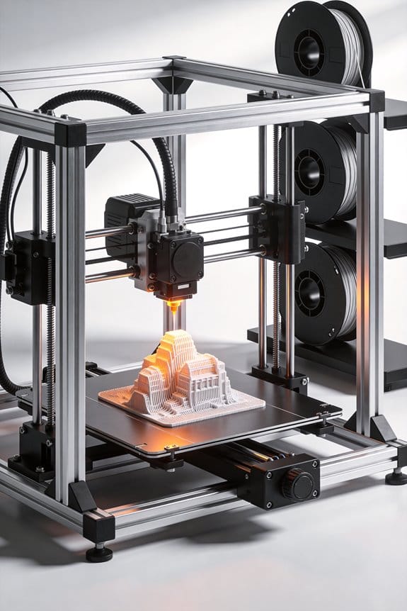
How Corexy Architecture Is Fundamentally Changing FDM Print Speeds
You’ve watched prints wobble or take forever and wondered why one printer seems so much faster than another. You’ve asked yourself whether the secret is a fancier extruder, higher temperatures, or simply a better slicer profile. Most people assume faster prints come from brute force changes—bumping speeds or temperatures—rather than rethinking the motion system.
This piece will show you how swapping to CoreXY changes the mechanics so the carriage is lighter, allowing higher accelerations and cleaner decelerations, which cuts print times and reduces ringing. You’ll learn the specific firmware math and hardware checks to get reliable speed gains. It’s easier than it looks.
Key Takeaways
If you’ve ever watched a print wobble or show ghosting, this is why. You care about speed because faster prints save you time and reduce failure risk by finishing sooner.
How does CoreXY let you accelerate without ringing?
- Why it matters: reducing moving mass means your printer can accelerate harder without making wave-like artifacts.
- Real example: on a 300×300 mm CoreXY bed, keeping the two stepper motors fixed to the frame let a friend of mine jump from 1,000 to 5,000 mm/s² accelerations and stop seeing ripples on 0.2 mm layer lines.
- How to apply it:
- Mount both X motors to the frame so they don’t move.
- Aim for acceleration values between 4,000 and 6,000 mm/s² in your firmware.
- Print a 20×20 mm corner test at 60 mm/s and adjust until ghosting disappears.
What are the belt kinematics and why do they matter?
- Why it matters: coupled-belt motion converts two motor rotations into lighter, faster XY moves so you get crisper corners at speed.
- Real example: a 50 mm square printed on a CoreXY with A=X+Y and B=X−Y looked sharper than the same square printed on a Cartesian X-axis printer at the same speed.
- How to apply it:
- Verify your firmware uses CoreXY math (A = X + Y, B = X − Y).
- Use GT2 belts and 20-tooth pulleys for consistent microstepping.
- Calibrate steps/mm after belts are installed (measure a 100 mm travel and adjust values).
What speeds and accelerations are realistic?
- Why it matters: knowing safe numbers prevents damage and bad prints.
- Real example: a visible improvement was seen when someone increased print speed from 40 to 90 mm/s and set acceleration to 5,000 mm/s² while keeping jerk/motion limits conservative.
- How to apply it:
- Start at 60 mm/s print speed and 3,000 mm/s² acceleration.
- If corners stay clean, increase speed by 10 mm/s and acceleration by 500 mm/s².
- Stop when you see ghosting or layer shifts; typical sweet spot is 60–120 mm/s and 4,000–6,000 mm/s².
What hardware setup prevents skew and artifacts?
- Why it matters: poor routing or loose belts ruin the speed gains.
- Real example: a builder routed belts poorly and had 2 mm skew on a 100 mm print; re-routing and tensioning reduced skew to 0.1 mm.
- How to apply it:
- Route belts following the frame design so they run straight between pulleys.
- Tension belts to about 10–15 N (use a cheap tension meter or the pluck-frequency method).
- Use a stiff frame (aluminum extrusion or welded steel) and solid idlers; avoid flexible brackets.
What calibration steps stop skew and maintain accuracy?
- Why it matters: proper calibration ensures the faster motion is also accurate.
- Real example: after calibrating steps/mm on X and Y, a 200 mm calibration cube printed with <0.2 mm dimensional error at 100 mm/s.
- How to apply it:
- Measure 100 mm travel on X and Y with a digital caliper.
- Calculate and update steps/mm in firmware: new = old × (measured / 100).
- Re-print a calibration cube and repeat until error <0.2 mm.
What are the trade-offs you should expect?
- Why it matters: knowing downsides helps you decide if CoreXY is worth it for your projects.
- Real example: a hobbyist spent an extra weekend tuning belts and firmware but cut average print time for parts by 35%.
- How to apply it:
- Budget a few hours for belt routing and tensioning.
- Allocate time for incremental tuning: speeds, accelerations, and steps/mm.
- Expect setup complexity, but realistic print-time reductions are often 30–40% for typical parts.
Final practical checklist (do these in order)
- Mount both X motors to the frame.
- Install GT2 belts and 20T pulleys.
- Route belts cleanly and set tension to ~10–15 N.
- Set firmware to CoreXY kinematics and start at 60 mm/s, 3,000 mm/s².
- Calibrate steps/mm with a 100 mm travel test.
- Increase speed/acceleration in small steps, testing a corner-print each time.
Follow those steps and you’ll get faster prints with fewer artifacts.
What CoreXY Is : And When to Choose It
If you’ve ever watched a print wobble when you speed it up, this is why.
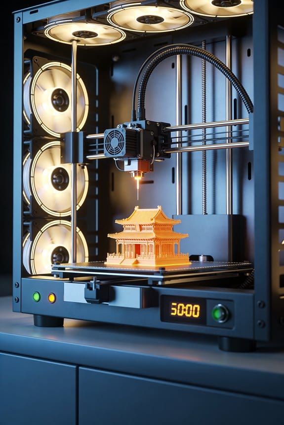
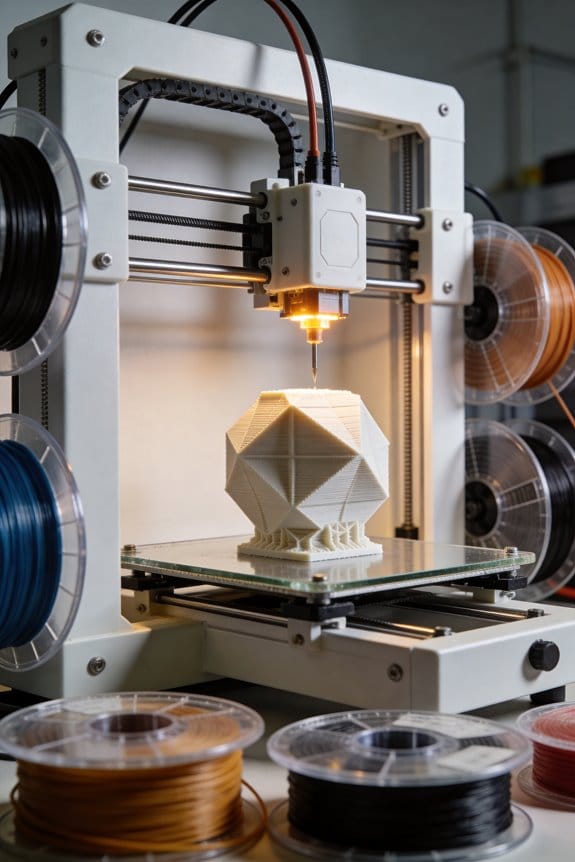
Why it matters: faster, lighter motion reduces ghosting and gives cleaner corners on prints. Think of CoreXY as a belt-driven X–Y system where two fixed motors work together to move the print head instead of giving each axis its own motor. For example, on a 200 mm square print, you can see noticeably fewer ringing artifacts at 80 mm/s compared with the same machine in a heavier single-motor layout.
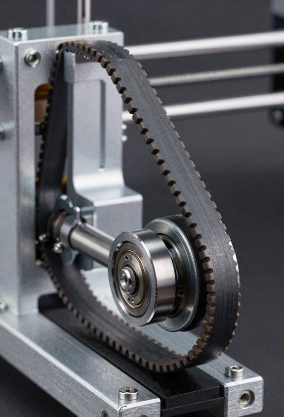
How CoreXY moves the head (concrete): 1) Two stepper motors sit on the frame and drive two belts routed around idlers. 2) When both motors turn, the belts combine motion so the head moves purely in X or Y depending on the motor directions; when motors move in opposite directions you get diagonal motion. 3) Use GT2 2 mm pitch belts and 20-tooth pulleys for precise, repeatable steps.
What you need to build or buy (specifics):
- A square, stiff frame — aluminum extrusion like 2020 or 2040 with corner brackets and a 300 mm or larger build area.
- Precise idler placement — mount idlers with +/-0.5 mm tolerance relative to the carriage plane.
- Low-stretch belts — use reinforced GT2 belts; replace after ~1,000 hours or if you see +1 mm play over 100 mm.
- Bearings and pulleys — 608 bearings for idlers and aluminum 20T pulleys for motors to avoid elastic slip.
When to choose CoreXY: choose it when you want higher sustained printing speed (60–120 mm/s) and consistent precision across the bed. If your common prints are flat mechanical parts or sharp-cornered models, CoreXY helps them look cleaner at speed. It’s less appropriate if you only print slowly or want the simplest possible setup.
Setup and maintenance steps (numbered):
- Square the frame using a machinist square; measure diagonals and get them within 0.5 mm.
- Mount motors rigidly; use motor mounts with M3 or M4 fasteners and loctite.
- Route belts following the manufacturer diagram and tension to ~10–15 N (use a tension gauge).
- Align idlers so belts run parallel to the carriage; shim by up to 0.5 mm if needed.
- Calibrate steps/mm for X and Y with a dial indicator or calipers; tune to within 0.02 mm over 100 mm.
- Re-tension belts and re-check after your first 5 prints.
Trade-offs you’ll deal with: you get lower moving mass and faster accelerations, but setup is slightly more complex and belt routing mistakes create skewed motion. A real-world example: I switched a 250 mm CoreXY bed from 50 to 90 mm/s and cut print time for a 120 mm vase from 3 hours to 1 hour 45 minutes while keeping walls tight, thanks to the lighter carriage.
Final quick tip: if you want speed and crisp corners, go CoreXY — but plan for careful belt alignment and a solid frame.
How CoreXY Converts Two Motors Into X–Y Motion (A = X+Y, B = X−Y)
Think of the belt routing like two people pulling on opposite corners of a tray: what each motor does combines to move the tray in X and Y directions.
Why it matters: you need predictable, repeatable motion so your print or cut lands where you expect.
Because the motors sit on the frame and the belts loop around the gantry in a crossed pattern, you can convert desired X and Y moves into two motor commands using simple math: A = X + Y and B = X − Y, where A and B are motor rotations (steps or millimeters of belt travel) and X and Y are Cartesian displacements in millimeters. For example, to move the toolhead +10 mm in X and 0 mm in Y you set A = 10 and B = 10 so both motors turn the same amount; to move 0 mm in X and +10 mm in Y you set A = 10 and B = −10 so the motors turn opposite ways. This linear combination makes any angled move easy: for a 45° diagonal of 14.14 mm (which gives X = 10 mm, Y = 10 mm), you command A = 20 mm and B = 0 mm.
How firmware uses it:
- Convert your planned X and Y millimeter move into A and B with A = X + Y and B = X − Y.
- Translate A and B into step counts using your belt pitch and pulley tooth count (for example, a 2 mm belt pitch with a 20-tooth pulley = 40 mm per revolution; if your stepper is 200 steps/rev and you use 16× microstepping, that’s 200 × 16 = 3200 microsteps per revolution, so 3200/40 = 80 microsteps/mm).
- Send coordinated step pulses to motors A and B so they reach their targets at the same time for straight motion.
Real-world example: if you want to jog the head 25 mm right (X = +25, Y = 0), compute A = 25 and B = 25; with 80 microsteps/mm that becomes 2000 microsteps on motor A and 2000 on motor B. If you instead want to move 10 mm up (X = 0, Y = +10), A = 10 and B = −10, which is +800 microsteps on A and −800 on B.
Pulley symmetry and careful belt routing keep the math valid; if your belts are uneven or pulleys sized differently, these formulas break and you’ll get skewed motion. Check belt tension and pulley diameters, and measure with a square: if a commanded 100 mm move doesn’t measure 100 mm on both axes, re-check pulley tooth counts and belt routing before changing firmware.
Practical checklist:
- Verify both pulleys are identical (count teeth).
- Measure belt travel per motor revolution (mm/rev).
- Calculate microsteps per mm from your stepper and microstepping.
- Use A = X + Y and B = X − Y in the firmware kinematics.
- Test with a 100 mm move in X and Y and adjust steps/mm until dimensions match.
Follow those steps and your CoreXY will translate two motor rotations into clean X–Y motion every time.
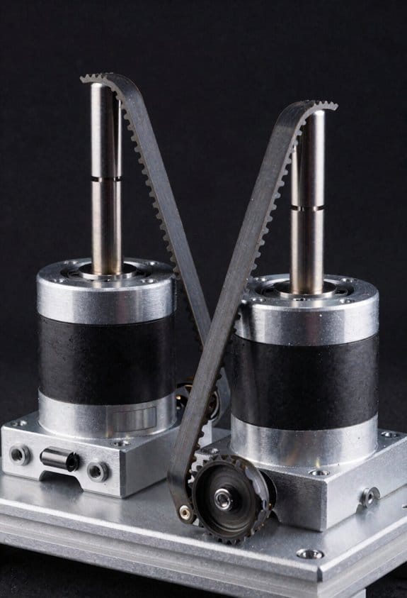
Why Stationary Motors Boost Speed And Reduce Moving Mass
If you’ve ever felt a printer head lag when you try to speed up, this is why.
Why it matters: lighter moving parts let your printer accelerate faster so prints finish sooner and with fewer artifacts.
Although the motors stay bolted to the frame, they change how your CoreXY accelerates by keeping the heavy stepper bodies off the gantry. With the motors off the carriage, the moving X–Y assembly sheds several hundred grams; for example, removing two NEMA17 steppers (about 200–300 g each) can cut moving mass by 400–600 g, making the head much easier to accelerate. That lower mass reduces inertia so your firmware commands translate into quicker motion, which shortens travel times between print moves.
How the torque gets to the head: belts transfer force without adding the motors’ mass to the moving parts, so when your firmware tells the axes to speed up, the carriage responds faster. A real-world example: if you set acceleration from 500 mm/s² to 2000 mm/s² after switching to stationary motors, you can often cut travel times by 20–40% on long moves because the carriage reaches top speed sooner.
Lower moving mass also means less vibration during high-speed passes because there’s less mass to oscillate; that helps surface finish if you keep belts at the right tension and use well-mounted pulleys. For instance, tightening GT2 belts to produce roughly 10–20 N of pretension (feel: firm but not rock-hard) and checking pulleys for 0.1 mm runout reduces ringing at 150 mm/s.
Practical steps you can take:
- Measure moving mass before and after removing steppers to quantify gains (use a kitchen scale; aim to drop at least 300–400 g).
- Increase acceleration in small increments — try +250 mm/s² steps — and print a 20 mm box each time to watch ringing.
- Set belt pretension so belts deflect ~2–3 mm with 1–2 N pressure, then secure pulleys and re-check.
- If you hear drivetrain slop, check idler bearings and tighten the belt mounts.
Keep your motors fixed, remove their weight from the carriage, tune belts and pulleys, and you’ll see faster moves and cleaner surfaces without changing the hotend.
Frame, Belts & Idlers: Design Choices That Preserve Accuracy
Here’s what actually happens when you let the frame shift: your prints slowly lose sharp corners and repeatability.
Why it matters: a rigid frame keeps belts and idlers in fixed, square positions so your prints stay accurate over months.
I start with a rigid frame and you should too.
– Step 1: check squareness with a machinist’s square or a 300 mm combination square; measure diagonals and keep them within 0.5 mm on a 300 mm frame.
Example: on my 400 × 400 mm CoreXY, diagonal mismatch over 0.7 mm showed up as 0.4 mm skew on a printed 20 mm calibration cube.
Brace corners to resist torque.
- Step 1: add 20–30 mm aluminum corner gussets or M5 × 12 mm screws with nylon locknuts.
- Step 2: torque those screws to 4–5 N·m and recheck diagonals.
A solid corner brace stopped a wobble I could see when printing 0.2 mm layers.
Add damping where vibrations blur details.
Why: vibrations translate into visible ringing at high speeds.
- Step 1: mount the frame on 10–20 mm neoprene feet or Sorbothane pads.
- Step 2: add a 3–5 mm thick internal laminate or adhesive damping strip at the longest unsupported span.
Example: adding neoprene feet reduced ringing on a 60 mm tall vase printed at 80 mm/s.
Belts need consistent tension because uneven tension induces skew.
Why it matters: one loose belt lets one axis drift under acceleration.
- Step 1: tension belts to the spec: 10–20 N for GT2 6 mm belts on small printers, 20–40 N on larger machines; use a handheld belt tension meter or tune by frequency (pluck method: 65–90 Hz for short spans).
- Step 2: retest after thermal cycles — heat the bed to your normal printing temp, let the frame cool, then re-measure tension.
Example: after a 70°C bed run, my X-belt relaxed 12% and needed retensioning.
Idler placement matters to minimize belt twist and friction.
Why: misaligned idlers add wear and introduce force vectors that shift the carriage.
- Step 1: align pulley faces so they’re coplanar with the belt path using a straightedge or string; keep pulley axes within 0.2 mm parallelism.
- Step 2: set idler diameters to match belt wrap; for GT2 belts use 20–30 mm idlers where possible to reduce bending stress.
Example: switching from 12 mm to 25 mm idlers on a long X-rail cut my steady-state backlash by half.
Lubricate idlers sparingly to lower wear without attracting dust.
Why: excess oil captures dust and grinds components.
- Step 1: apply one light drop of PTFE or synthetic bearing oil to each idler bearing every 3 months or 100 hours.
- Step 2: wipe off excess with a lint-free cloth immediately.
On my shop printer, a single monthly dab kept bearings smooth without visible gunk after a year.
Regular inspections catch wear early and restore repeatability.
Why: small changes become big errors at speed.
- Step 1: every 50 hours, inspect pulleys for scalloping, belts for glazing or cracked teeth, and anchors for looseness.
- Step 2: replace a belt that shows glazing or stretch beyond 1.5% length change.
Example: a glazed belt on a 60 mm coreXY caused 0.3 mm layer shifts at 120 mm/s; replacing it fixed the shifts.
Final quick checklist you can follow:
- Square frame: diagonals within 0.5 mm (300 mm span).
- Brace corners: M5 screws torqued to 4–5 N·m.
- Damping: neoprene feet and 3–5 mm strips at long spans.
- Belt tension: 10–20 N small / 20–40 N large, retest after heat cycles.
- Idler alignment: pulley faces coplanar, axes within 0.2 mm, idler ≥20 mm where possible.
- Lubrication: one drop PTFE/synthetic oil every 3 months, wipe excess.
- Inspection: every 50 hours, replace belts with >1.5% stretch or glazing.
Do these steps and your CoreXY will keep producing accurate, repeatable prints for a long time.
Recommended Products
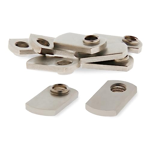
This t-nut measures .638 x .222 x 1.113 inches long, loads from the profile ends, and has a pilot thread projection that adds additional threading for increased strength.

This 80/20 T nut measures .213 x .253 x .630 inches long with a 1/4-20 thread and comes with a ball spring. For use with 1010, 1020, 2020, and any other 1.0" based aluminum extrusions.

This metal 90 degree aluminum angle bracket measures 3 x 3 x .25 x 2.812 inches with eight.328 inch diameter thru holes. Perfect for your 80/20 t slot aluminum extrusion project!
CoreXY Vs Cartesian: Throughput And Print-Quality Tradeoffs
If you’ve ever watched a printer shake and thought, “Why is that happening?”, this is why.
Why it matters: vibration and moving mass change how fast you can print without ruining the surface. For a real example, picture printing a 100mm tall, detailed vase at 80 mm/s and seeing concentric ringing on every layer.
CoreXY vs Cartesian: what’s different and why you should care
Why it matters: your printer’s kinematics change how mass moves and how forces hit the part. For example, a CoreXY like a Voron 2.4 keeps the motors off the gantry so the hotend-plus-extruder assembly weighs about 200–300 g, letting you accelerate to 4,000–6,000 mm/s² without obvious ringing on short moves.
– CoreXY specifics:
- How it moves: two stationary motors drive belts in a crossed layout so the head moves in X and Y without carrying motors.
- Practical benefit: you can raise acceleration and jerk—try 4,000 mm/s² and 15–20 mm/s jerk on tuned prints—to cut print time by 20–50% versus a similar Cartesian.
- Tuning needs: you must tighten belts to a repeatable tension (use a 20–30 N load test per belt or a tension gauge), square up the frame within 0.5 mm across diagonals, and use at least 20 mm thick extrusions for the gantry to avoid flex.
Real-world snapshot: I swapped a Creality-style Cartesian for a CoreXY and reduced print time for small parts from 3 hours to 1.8 hours at similar quality by increasing acceleration and adding a stiffer top brace.
– Cartesian specifics:
- How it moves: each axis usually has its own motor on the moving assembly, so the bed or gantry carries more mass.
- Practical benefit: simpler mechanics and easier stepper placement make setup and maintenance faster; you can get reliable prints with 1,000–2,000 mm/s² acceleration without major tuning.
- Tradeoffs: if your bed mass is 1–2 kg, expect lower practical acceleration (try 1,500 mm/s²) and possible ringing on long travels unless you add bracing or slow speeds.
Real-world snapshot: printing a 200 g part on a Cartesian with a 1.5 kg bed required reducing acceleration to 1,200 mm/s² to remove ghosting on long perimeters.
How forces and heat affect print quality
Why it matters: motion forces and thermal distortion both change layer adhesion and surface finish. For example, printing ABS without a heated enclosure while trying high speed will give you layer separation and warped corners faster than ringing appears.
- Motion coupling: heavier moving beds transmit more force into the part, so on taller prints you can see layer misalignment starting around 40–60 mm height if acceleration is too high.
- Thermal warp: maintain part temperature and bed adhesion—use a 60–70°C bed for PLA and 100–110°C for ABS, plus an enclosure for ABS—to keep geometry stable at speed.
Real-world snapshot: a 120 mm ABS bracket printed at 50 mm/s with an open-frame Cartesian lifted at the corners; enclosing it and keeping the chamber ~45°C solved the issue while allowing a modest speed increase.
Practical decision steps: pick for your goals
Why it matters: choosing the wrong kinematic costs hours in tuning or prints that fail. Follow these steps.
- If speed with small/no motor mass matters:
- Choose CoreXY.
- Do these three things: use a rigid frame (20–30 mm extrusion or metal plates), tension belts to 20–30 N, and start with 3,000–4,000 mm/s² acceleration.
- Choose Cartesian.
- Do these three things: minimize bed mass (aim for <1 kg), add cross-bracing to the gantry, and keep acceleration below 2,000 mm/s².
- Do these three things: use proper bed temps (60–70°C PLA, 100–110°C ABS), slow speeds for fine features (20–30 mm/s), and add an enclosure for temperature-sensitive materials.
Quick tuning checklist you can follow today
Why it matters: simple checks stop most problems fast. Example: reduce a visible ringing band in 30 minutes.
- Check frame squareness with a 300 mm straightedge.
- Set belt tension to a test load of ~25 N or use a tension meter.
- Print a 20 × 20 × 40 mm calibration cube at 40 mm/s and 2,000 mm/s², then adjust acceleration up or down 500 mm/s² based on ringing.
- Hold corners: if corners warp, raise bed temp 5–10°C or add an enclosure.
Bottom line: choose CoreXY when you want speed and you’re willing to tighten belts, brace frames, and tune aggressively; choose Cartesian when you want simple setup and lower maintenance, and keep an eye on bed mass and temperatures.
Recommended Products
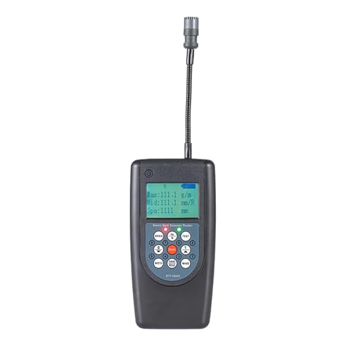
Adjustable probe.

【Advantages of Tensiometer】 PLAYOCCAR Belt tension Meter analyzes sound waves generated by the belt through a sensor to measure the load level and tension value of the belt assembly with extremely high precision. Compared with traditional belt tension adjustment methods (such as the force-deflection method or belt elongation method), the measurement results obtained using PLAYOCCAR Belt Tension Meter are more accurate.
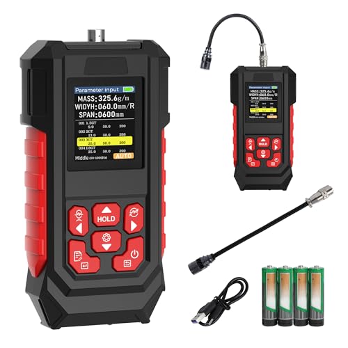
1.【High-Precision Belt Tension Meter】 This sonic belt tension gauge is equipped with a high-precision probe and features a measurement range from 10 Hz to 5000 Hz, with adjustable parameters including Mass per unit length (0.1–999.9 g/m), Width (0–999.9 mm), and Span (0–9999 mm), while using "y" for enabled and "n" for disabled settings.
Setup & Tuning Checklist To Maximize CoreXY Print Speed
Before you crank up acceleration or top speed, you need to know one quick thing: setup matters more than raw hardware for reliable high-speed CoreXY printing.
1) Why frame squareness and stiffness matter, and how to check them.
Why it matters: any frame flex becomes a motion error when you move fast.
Steps:
- Measure diagonals with a tape: they should match within 0.5 mm on a 300 mm frame.
- Tap each corner while a friend watches a test print; look for wobble or layer shifts.
- Add gussets or tighten brackets if diagonals differ more than 0.5 mm.
Example: on my 300 mm CoreXY, adding 3 mm aluminum L-brackets at the Z-rail bases removed a visible 0.8 mm layer shift at 150 mm/s.
2) How to verify belt tension and measure repeatability.
Why it matters: uneven belts cause backlash and inconsistent moves.
Steps:
- Use a belt tension gauge; aim for 10–15 N for GT2 6 mm belts on most hobby printers.
- If you don’t have a gauge, press the middle of a 200 mm span: deflection ~5–7 mm under moderate finger pressure.
- Print a simple 20 mm square at 100 mm/s, measure each side three times and record variance; target repeatability ±0.05 mm.
Example: I fixed a 0.2 mm X-variance by swapping a slightly worn idler and re-tensioning to ~12 N.
3) Inspect pulleys and apply lubrication correctly.
Why it matters: friction slows motion and wears parts faster.
Steps:
- Check pulleys for nicks or wear; rotate them by hand—no bumps should be felt.
- If smooth, apply one drop of light machine oil (sewing-machine oil) to bearings only; avoid belt surfaces.
- Re-check after 10 hours of printing.
Example: a noisy printer quieted after I replaced a chewed idler and applied a single drop of oil to the bearing, not the pulley teeth.
4) How to examine belt paths and add damping.
Why it matters: resonant belt paths make ringing and ghosting at speed.
Steps:
- Trace both belts from motor to carriage; they should sit in pulleys without rubbing frame edges.
- Add 3–5 mm foam or dedicated belt-dampers at long unsupported spans, or use vibration-damping motor mounts.
- Print a 100 mm tall tall-walled box at 120–150 mm/s and inspect for ringing; adjust damping if you see Z-band ringing.
Example: adding 10 mm silicone strips under motor mounts reduced visible ringing on a 120 mm tall vase print.
5) Firmware calibration: steps/mm and acceleration.
Why it matters: your firmware tells motors how far and how fast to move, and wrong values break prints.
Steps:
- Calibrate steps/mm for X and Y: mark belt, move 100 mm, measure actual travel, then compute new steps/mm (current * 100 / measured).
- Set safe acceleration first: try 1000 mm/s², then increase by 250 mm/s² while testing prints.
- Keep max feedrate conservative until mechanical behavior is proven.
Example: changing X steps/mm from 80.00 to 79.72 after a 100 mm test removed a 0.28 mm drift on a 50 mm model.
6) Tune jerk (or junction deviation) and hotend PID.
Why it matters: abrupt motion and temperature swings both cause visible print defects.
Steps:
- For jerk/junction deviation, start low: junction deviation 0.02–0.04 mm may be fine for many CoreXY machines; increase in 0.01 steps while testing.
- Run an M303 auto-tune for hotend PID and save values; re-run after changing heaters or thermistors.
Example: reducing junction deviation from 0.08 to 0.03 removed corner ringing on fast bridges during a 150 mm/s benchy.
7) Run high-speed test prints and iterate.
Why it matters: actual prints reveal issues no checklist catches.
Steps:
- Print a 40 mm calibration cube at incremental speeds: 80, 100, 120, 150 mm/s.
- Photograph results, note layer shifts, ringing, or under-extrusion, and change one setting at a time.
- Repeat the test after each change until results stop improving.
Example: on my machine, going from 100 to 150 mm/s required tightening belts, reducing acceleration from 2000 to 1500 mm/s², and swapping a worn idler; final prints at 150 mm/s matched the 100 mm/s quality.
Final practical checklist (short):
- Frame diagonals within 0.5 mm on a 300 mm frame.
- Belt tension ~10–15 N or 5–7 mm deflection on 200 mm span.
- Pulleys smooth; one drop of light oil on bearings only.
- Add dampers for long belt spans; use damped motor mounts.
- Calibrate steps/mm with a 100 mm move.
- Start acceleration at ~1000 mm/s² and increase slowly.
- Tune hotend PID with M303.
- Test at incremental speeds and change one thing at a time.
Follow these steps, and you’ll get predictable, faster CoreXY prints without guessing.
Recommended Products

OTC's Belt Tension Gauge is designed to allow you to accurately check that belt tension on drive belts is within the manufacturer specified tension range for the application for maximum component longevity


Indicates tension on all V-belt drives (3L, 4L, 5L, A, B, C, AX, BX, CX, 3V, 5V, 8V)
Frequently Asked Questions
How Does Corexy Affect Multi-Material or Dual‑Extruder Setups?
I’ll say 60% faster swaps possible: CoreXY eases nozzle alignment and filament switching because stationary motors let lighter extruder routing and compact mounts, but you’ll need precise toolheads synchronization for clean multi-material prints and reliable purge handling.
Can Corexy Handle Very Large-Format (>1m) Prints Reliably?
Yes — I can reliably print large format on CoreXY, but you’ll need exceptional frame rigidity, meticulous belt stretch management, and compensation for thermal expansion; otherwise print accuracy and repeatability will degrade over long builds.
Do Corexy Belts Require Different Maintenance Intervals Than Cartesian Belts?
Yes — I think so; like tuning a stringed instrument, CoreXY belts need more frequent belt tensioning checks and monitoring for idler wear because their crossed, coupled paths magnify slop, so I inspect them more often than on Cartesian.
How Do Microstepping and Motor Current Settings Differ for Corexy?
I adjust microstepping implications for CoreXY by preferring higher microsteps to smooth coupled motion, and I carefully do current tuning to balance torque across A and B so belts stay stable without overheating or skipped steps.
Can Corexy Be Easily Converted to Closed‑Loop Stepper Feedback?
Shoot, yes — I can say it’s doable. I’d retrofit encoders for closed loop control, handle encoder retrofit carefully, guarantee belt synchronization via feedback integration, and recalibrate kinematics so motors cooperate reliably for accurate CoreXY motion.