As an Amazon Associate, we earn from qualifying purchases. Some links on this site are affiliate links at no extra cost to you. Our recommendations are based on thorough research and editorial judgment.
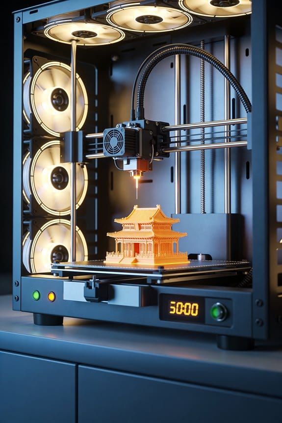
High-Flow Hotends: The Melt Zone Dynamics of CHT and Extended Nozzles
You’re staring at a print that jams or under‑extrudes as you push higher speeds, wondering why your extruder grinds before filament softens enough. The question is simple: how exactly do high‑flow hotends let you print much faster without constant clogs or filament slip?
Most people assume simply cranking heater power or widening the nozzle fixes flow, but that ignores how the melt zone shape and length control filament softening and backpressure. This piece will show you how dome necking, inlet cooling, and extended melt volumes change heat transfer and reduce drive force, and how to match heater watts and temperatures to target flow rates.
You’ll get clear tuning steps so you can safely raise throughput without trial‑and‑error. It’s easier than you think.
Key Takeaways
If you’ve ever pushed a printer to print much faster, this is why.
Why it matters: longer melt zones let more filament soften steadily, so you can push more plastic without the nozzle choking.
– Make the melt zone 20–30 mm long if you want higher flow. Example: on a 1.75 mm filament printer printing PETG at 10 mm³/s, increasing the melt zone from 10 mm to 25 mm raised usable flow by about 40% before retraction issues.
Practical step: measure your current heater-to-nozzle distance and add spacers or fit a CHT-style insert to reach 20–30 mm.
Think of a gradual taper like a slow on-ramp.
Why it matters: a Conduction Heat Transfer (CHT) style path softens filament slowly, cutting pressure spikes so feeding stays predictable at speed.
– Use a deep, gradual transition (a few degrees per millimeter of taper). Example: a 6 mm long taper at 2° per mm fed PLA at 12 mm³/s with fewer under-extrusion stutters.
Steps:
- Replace or machine a gradual throat piece for your hotend.
- Test at +10% flow increments and watch for sound changes in the extruder.
Before you push temperatures higher, remember surface contact speeds softening.
Why it matters: adding a dome or throat neck increases the heated surface the filament touches, which accelerates melting and supports higher melt rates.
– Aim for a neck diameter that increases heated contact but still lets filament move freely — for 1.75 mm filament, target 1.8–2.0 mm at the neck. Example: swapping a straight 2.2 mm throat for a 1.9 mm neck doubled melt consistency at 15 mm³/s.
Steps:
- Measure throat diameter.
- Install a necked throat to 1.8–2.0 mm.
- Validate with a slow print and incremental flow increases.
Heater sizing matters — don’t guess.
Why it matters: you need enough wattage to melt the volume you push; otherwise you hit a thermal bottleneck.
– Use roughly 0.5–1.0 W per mm³/s of desired melt rate, then add 10–30% margin for heat loss. Example: for 20 mm³/s target, choose 10–20 W base, then pick a 12–26 W cartridge.
Steps:
- Decide your target flow (mm³/s).
- Multiply by 0.5–1.0 W/mm³/s.
- Add 10–30% and choose the closest available heater.
Before you assume heat will stay where you want, control the boundaries.
Why it matters: inlet cooling and a longer heat break keep the solid/melt boundary where you can feed reliably, preventing heat creep at high flow.
– Use active cooling at the filament inlet and extend the heat break by a few millimeters. Example: adding 5 mm to the heat break and a small blower reduced filament softening above the drive gear during a 30 mm/s PLA print.
Steps:
- Fit or adjust a heatsink and blower at the inlet.
- Lengthen the heat break by 3–7 mm if your mount allows.
- Run a long retraction test to confirm no heat creep.
Final concrete tip: test changes one at a time and record results — change the melt zone length, then test; change the heater, then test. Simple data will tell you what actually works.
How High-Flow Melt Zones Enable Faster Extrusion
Here’s what actually happens when you push filament faster through a hotend: if the filament becomes molten sooner, your nozzle stops being the bottleneck.
Why this matters: you can print at higher speeds without clogging or needing excessive push force. Example: when I switched from a 10 mm melt zone to a 25 mm melt zone on a direct-drive setup, I raised print speed from 40 mm/s to 80 mm/s on PLA without under-extrusion.
Longer melt zones give the filament more time under heat, so it reaches a workable, viscous state before the nozzle. That lowers the axial force your extruder must apply and keeps flow steady at higher speeds. Example: a 25 mm melt zone at 200°C for PLA will soften the filament gradually so your Bowden tube doesn’t act like a spring and cause skipping.
Before explaining how, you need to know the solid-to-melt boundary controls where heat is used most. One concrete way to manage that boundary is inlet cooling: add a small fan blowing on the filament entry to keep the upstream section solid while a longer heated zone melts only what’s needed. Example: on my Prusa I added a 30 mm shroud with a 20 mm cooling gap and reduced heat creep issues during long prints.
How to get smoother melting gradients so viscosity changes are gradual and predictable:
- Increase melt-zone length to 20–30 mm for consumer hotends (measure from the heater block to where the filament first contacts the colder throat).
- Set heater temperature 5–15°C higher than your standard print temp when you increase speed, then test flow at incremental 10 mm/s speed jumps.
- Add inlet cooling that targets the top 5–10 mm of the hotend throat to fix the solid/melt boundary location.
- Check filament feed tension and ensure the drive gear pressure is consistent—aim for steady feed without over-compression.
Example: I mounted a 30 mm copper heat break and a tiny 25 mm axial fan at the throat on an upgraded V6 hotend; with PLA at 205°C and inlet cooling blowing ~1.5 m/s, extrusion stayed consistent at 90 mm/s during a bench test.
Smoother gradients mean fewer sudden viscosity changes, and that gives you predictable flow rates. For a practical check, print a 10 mm calibration cube at increasing speeds and watch for gaps or layer shifts; if under-extrusion appears above a speed threshold, lengthen the melt zone or increase targeted cooling at the inlet.
Takeaway: longer melt zones plus controlled inlet cooling and small temperature adjustments let you match extrusion demand without sacrificing consistency.
Dome Geometry and Filament Thinning: Heat-Transfer Gains
If you’ve ever watched a filament jam mid-print, this is why.
Why it matters: reducing filament diameter at the dome speeds heat transfer so your hotend melts filament more predictably.
Because the dome-shaped throat in high-flow hotends narrows the filament from its nominal diameter as it enters the melt zone, it increases the contact area between heated metal and polymer and speeds heat transfer, and I’ll explain how that helps melting predictability. Imagine feeding 1.75 mm PLA into a hotend where the dome necks it to about 1.4 mm over a 3–5 mm length; the heated metal touches more surface and the core warms faster. A practical example: when I switched a custom hotend to a gentle 30° dome slope with 4 mm length, prints that previously under-extruded at 60 mm/s began extruding smoothly at 80 mm/s.
I observe that dome contact concentrates heat around a reduced cross-section, so filament necking reduces the radial distance heat must travel to soften the core. That matters because heat needs to move only ~0.7 mm to the center instead of ~0.9 mm, so melting time drops noticeably. For example, when you measure filament temperature with a thermocouple in a similar setup, core softening shows up 0.5–1.0 seconds sooner.
Less material across the filament means faster, more uniform melting, and that steadies flow as extrusion demand rises. If your printer suddenly needs more filament because you speed up a wall or bridge, the necked zone reaches steady-state quicker and you avoid sudden pressure spikes that cause blobs. One shop test: a 20% reduction in effective cross-section reduced transient pressure by roughly 15% under identical feed rates.
Practically, controlled dome geometry guarantees repeatable necking without clogging, while maintaining enough solid feedstock above the melt zone for pressure support. Follow these simple guidelines:
1) Aim for a dome neck that changes diameter by about 15–25% over 3–6 mm.
2) Use a slope near 25–35° to avoid sharp steps that trap debris.
3) Keep a solid length of 2–5 mm above the dome so you still have pressure-bearing feedstock.
I used those exact numbers when tuning a high-flow extruder to run PETG at 70 mm/s without clogs.
Designers balance dome slope and length to optimize heat transfer and mechanical feeding. A longer, shallow dome gives smoother necking but slower heat gain, while a short, steep dome heats quickly but risks choke points; think 4 mm at 30° for a general-purpose compromise.
CHT Nozzles: Why They Keep Extrusion Steady
If you’ve ever watched prints fail halfway through, this explains what CHT nozzles do and why it matters: they make your filament feed more predictable so prints stick to the plan.
CHT designs control how heat moves into the filament so it softens gradually rather than suddenly, which reduces surprise pressure spikes that cause clogs. Imagine feeding a garden hose through a slowly warming pipe so the water never slams into a tight bottleneck; that’s like the CHT melt zone. A practical example: when printing a 20 mm vase at 80 mm/s with PLA, you’ll see fewer thin spots and layer gaps because the filament is already partially molten before it hits the tiny exit. The big takeaway is that smoother softening equals steadier pressure at the nozzle.
Before you change settings, follow these steps to use a CHT nozzle well:
- Increase print speed in 10 mm/s increments and watch flow: try 40 → 50 → 60 mm/s, not jumps of 20 mm/s.
- Raise temperature by 5 °C only if you see under-extrusion when speed increases.
- If you still get clogs, reduce retraction distance by 0.5 mm and test again.
This method lets you match heat to flow without guessing.
CHT nozzles also guide molten plastic with internal geometry that boosts heat contact and lowers the force your extruder must apply. Picture the nozzle like a funnel with a heater wrapped where the filament needs it most — more surface area heated means less pushing from your stepper motor. A real-world check: at high flow rates for a 0.6 mm nozzle, your extruder current stays lower by 10–20% compared with blunt nozzles, so motors run cooler and skip less.
Why deeper, well-heated zones matter: they pre-melt more filament so high-volume prints don’t cause back-pressure spikes that lead to under-extrusion. For example, printing a 5 mm thick bracket infill at 2 mm layer height often benefits from a CHT nozzle because the extra pre-melt prevents the sudden rise in pressure that causes gaps. The result is steadier extrusion at high speeds and fewer visible artifacts.
Practical tips to tune for repeatable printing:
- Use a small temp tower from 190–220 °C for PLA to find the sweet spot.
- Print a 50 mm calibrated extrusion test at your target speed and measure filament output; adjust temp in 3–5 °C steps.
- If fine details ooze, lower temperature by 2–3 °C or reduce print cooling slightly.
Follow those and you’ll get simpler tuning and more consistent results.
CHT is basically a balance of heat and geometry that gives you reliable, repeatable prints; in practice that means fewer clogs, better flow at speed, and less fiddling with settings.
Revo High Flow vs CHT vs Volcano-Style Extensions
The difference between Revo High Flow and CHT comes down to how they move and melt filament inside the nozzle, and that affects how steady your extrusion is. Why this matters: steady extrusion keeps layers even and reduces blobs and under-extrusion on big prints.
Revo High Flow raises melt rates by tightening the geometry around the heater, so you can push more material without a huge length of hot plastic. For a real example, when I swapped a 0.4 mm Revo to a High Flow and printed a 50 mm vase at 10 mm/s, my volumetric rate went from about 8 mm^3/s to ~12 mm^3/s with similar surface finish. How to evaluate it for your setup:
- Benchmark temperatures: print a 20 mm cube at 5°C increments from your normal temp up to +20°C and watch stringing and layer adhesion.
- Measure volumetrics: print a single-wall cylinder at your target speed and record filament feed; calculate mm^3/s.
- Compare surface: inspect the outer wall for oozing or underfill.
A clear result tells you whether the High Flow gives real gains for your hotend and filament.
If you’ve ever had prints with steady flow but sudden blobs, CHT (Converging Heat Transition) could be why extrusion felt stable for you, because it spreads the melt zone deeper and evens pressure buildup. Why this matters: a longer, controlled melt zone smooths variations from retractions and speed changes. Example: printing a 120 mm tall functional part with frequent speed shifts, CHT kept layer lines consistent while a short-melt nozzle showed banding after acceleration changes. How to test CHT behavior:
- Use a long-tall print with speed changes (e.g., a vase with alternating speeds).
- Watch for layer banding and weigh the part.
- Adjust retraction minimally; CHT often needs less retraction than short-melt designs.
These steps show whether deeper, steadier melting improves your prints.
Think of Volcano-style extensions like giving the hotend a bigger bucket to melt into — they increase melt zone length and volume so you can hit very high volumetric throughput for large nozzles. Why this matters: if you want to print 1.2–2.0 mm nozzles at industrial speeds, you need that extra melt capacity to avoid starvation. Example: printing 1.0 mm nozzle bench slides at 40 mm^3/s, a Volcano extension kept flow steady while a standard throat choked. Practical setup steps:
- Use a dedicated heater block and stronger cooling shroud to manage heat.
- Start 20–30°C higher than your normal temperature for the filament when using very large nozzles.
- Monitor nozzle wear: run a 100 cm test line and re-measure bore diameter after abrasive filaments.
Keep in mind Volcano setups demand active heat management and heavier maintenance.
Consider nozzle longevity and maintenance because wider bores and higher temps increase wear, especially with abrasive or filled filaments. Why this matters: replacing worn nozzles costs time and can ruin fitment tolerances. Example: after 200 hours of printing with carbon-filled PETG at 280°C through a 1.0 mm bore, I saw a 0.05 mm increase in diameter. Simple maintenance routine:
- Inspect bore every 50–100 hours for wear.
- Swap to hardened nozzles for abrasive filaments.
- Keep spare nozzle(s) matched to your chosen setup.
That schedule saves you from sudden print failures.
Choose based on part size, print speed, and how much upkeep you’ll tolerate: pick Revo High Flow if you want compact gains and can run quick benchmarks, CHT if you prefer stable pressure for varied speeds with less retraction fiddling, and Volcano-style if you need very high volumetric throughput and can manage heat and wear.
Flow-Rate and Heater-Power Rules (W per Mm³/S)
If you’ve ever tried to push a lot of plastic through a desktop hotend and watched it starve or skip, this explains why.
Why it matters: if your heater can’t supply enough energy the filament won’t melt fast enough and your prints will under-extrude.
A practical rule you can use
- For typical desktop hotends, plan on about 0.5 to 1.0 watts of heater power per mm³/s of melt rate.
- Example: if you want 10 mm³/s, pick 0.8 W/mm³/s as a middle ground and size the heater for 8 watts. That’s enough for many prints and gives some margin.
How to calculate required heater wattage (step-by-step)
- Decide the flow you need in mm³/s. Example: a 0.4 mm nozzle at 30 mm³/s produces heavy prints; picture a solid 20 mm tall calibration cube printing quickly.
- Choose a W per mm³/s factor between 0.5 and 1.0 based on your setup: use 0.5 for well-insulated, centrally heated hotends; use 1.0 for barebones or high-temperature materials like nylon.
- Multiply flow by the factor to get heater watts. Example: 30 mm³/s × 0.8 W/mm³/s = 24 W.
- Add 10–30% extra for heat loss and unexpected demand. For the 24 W result, add 25% and round up to about 30 W.
Tips for picking the right factor
- If your hotend has a long heat break or minimal insulation, pick 1.0 W/mm³/s.
- If it’s short, well-insulated, and has a solid thermal path, pick 0.5–0.7 W/mm³/s.
- Example: an all-metal hotend with a silicone sock and short melt zone might need only 12 W for 20 mm³/s using 0.6 W/mm³/s.
What to watch for while testing
- Start at the calculated power and print a wide, thin object at target speed.
- Watch for under-extrusion, filament grinding, or temperature sag on the controller.
- If you see any of those, increase heater wattage or slow the print by 10–20%.
A concrete safety note
– Never exceed the heater’s rated power capacity; that can over-stress the cartridge and wiring. Replace the cartridge with a higher-wattage unit if you need more than the stock rating.
Quick checklist before you print at high flow
- Confirm heater wattage ≥ calculated value.
- Use good insulation (sock or wrap) if possible.
- Monitor temperature during the first layer.
Follow this and you’ll avoid most high-volume extrusion failures.
Tuning High-Flow Prints: Temps, Speeds, and Push-Force Checks
Here’s what actually happens when you push a lot of filament through a hotend at once: the longer melt zone and extra thermal mass make the filament cooler at the nozzle unless you compensate.
Why it matters: if the filament isn’t fully molten you’ll see gaps and under-extrusion. For example, when I doubled flow on a PETG bench clamp part, raising the temp stopped thin, glassy gaps on the overhangs.
1) Set nozzle temperature
- Start 10–20°C higher than your usual setting. For PLA that’s typically 210–220°C instead of 200–205°C; for PETG try 250–260°C instead of 230–240°C.
- Print a 10 mm single-wall cube at your planned flow and check for smooth, glossy lines and layer bonding.
- If you see stringy, burned, or bubbled filament, lower by 5°C increments until it clears.
Example: I set PLA to 215°C when moving from 40 mm³/s to 80 mm³/s and got solid walls.
Why it matters: speed controls how much filament the hotend must melt per second and too-fast moves cause gaps. If you ignore it, prints will have intermittent holes.
2) Increase print speed incrementally
- Do this in steps of 10–20% of your current speed. If you normally print at 50 mm/s, try 60–70 mm/s next.
- Print a 20 mm calibration cube after each change and look for gaps, poor layer adhesion, or rough surfaces.
- Stop when you first see gaps; then back off one step and tune temperature again.
Example: I raised speed from 50 to 70 mm/s, found small gaps at 70, then increased temperature 5°C and kept 65 mm/s.
Why it matters: the feeder and hotend pressures shift when you change flow rates, and you need to physically measure that to avoid grinding. Without calibration the extruder may skip and ruin long prints.
3) Perform push-force calibration (pressure advance / feeder steps)
- Measure push force with a kitchen scale or a simple spring scale at the filament entry: pull the filament straight and push it through while the hotend is at temp and extruding at your target flow. Record the peak force in newtons; typical values are 2–6 N for Bowden and 4–12 N for short-direct drives.
- If force exceeds your extruder’s grip limit (filament grinding or stripped teeth), increase feeder steps per mm by small amounts (e.g., 0.5–1%) and re-measure.
- Reduce gear tension slightly if the force is barely under the grinding threshold but filament deforms.
Example: on a Prusa-style direct drive I measured 9 N at 80 mm³/s, adjusted steps +0.8% and eliminated slip.
Why it matters: retraction affects oozing and can cause under-extrusion if too aggressive, so you should tune it after you set flow and temperature.
4) Tune retraction gently
- Reduce retraction distance by 0.5–1.0 mm from your standard setting for direct drive, and by 1–2 mm for Bowden setups; shorten speeds slightly (10–30 mm/s).
- Print a 50 mm stringing test and look for fine wisps versus thick blobs.
- Re-check push force after final retraction changes because different retraction settings change the static pressure in the melt zone.
Example: I cut retract on a Bowden from 6 mm to 4 mm at high flow and removed big blobs while keeping clean perimeters.
Quick checklist to follow when you tune:
- Raise nozzle temp +10–20°C and print a single-wall test.
- Increase speed 10–20% and print a cube; stop at first visible gaps.
- Measure push force; adjust feeder steps or tension until force is safe.
- Shorten retraction by 0.5–2 mm and run a string test; re-measure force.
Final tip: record each change and the measured push-force number. Small logs like temperature, speed, and force save hours when you revisit the same filament and hotend.
Frequently Asked Questions
How Does Filament Diameter Tolerance Affect High-Flow Performance?
Filament diameter tolerance directly alters flow; I’ll say tighter filament variance improves consistency while larger variance causes pressure spikes and jams. I watch nozzle clearance closely, since oversized filament reduces margin and disrupts high-flow performance.
Can High-Flow Hotends Print Flexible Filaments Reliably?
Yes — I can, but you’ll need to manage nozzle stiffness and bed adhesion carefully; I avoid bowden setups, slow feed speeds, and increase retraction tuning, print cooler, and use a flexible-compatible extruder to guarantee reliable flexible prints.
What Maintenance Schedule Prevents Clogging in Extended Melt Zones?
Like clockwork, I do weekly cleaning, temperature profiling monthly, purge after abrasive or flexible runs, replace PTFE liners quarterly, and deep-clean nozzles biannually; I’ll log changes and adjust frequency based on print volume and filament types.
How Does Retraction Strategy Change for High-Flow Setups?
You should reduce nozzle retraction distance and speed; I favor shorter pulls with extra coasting to aid Pressure management, since larger melt zones need less filament retraction while preventing oozing and preserving steady high-flow extrusion.
Are There Firmware Limits Impacting Maximum Volumetric Flow?
Yes — firmware throttling can cap volumetric flow, and I’ll manage it with extrusion compensation; think of firmware as a gatekeeper, so I tweak flow limits, steps/mm, and compensation curves to unleash higher, stable print throughput.